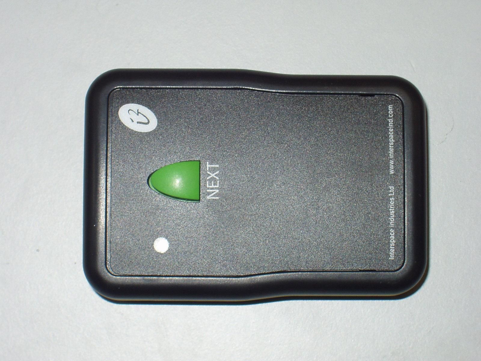
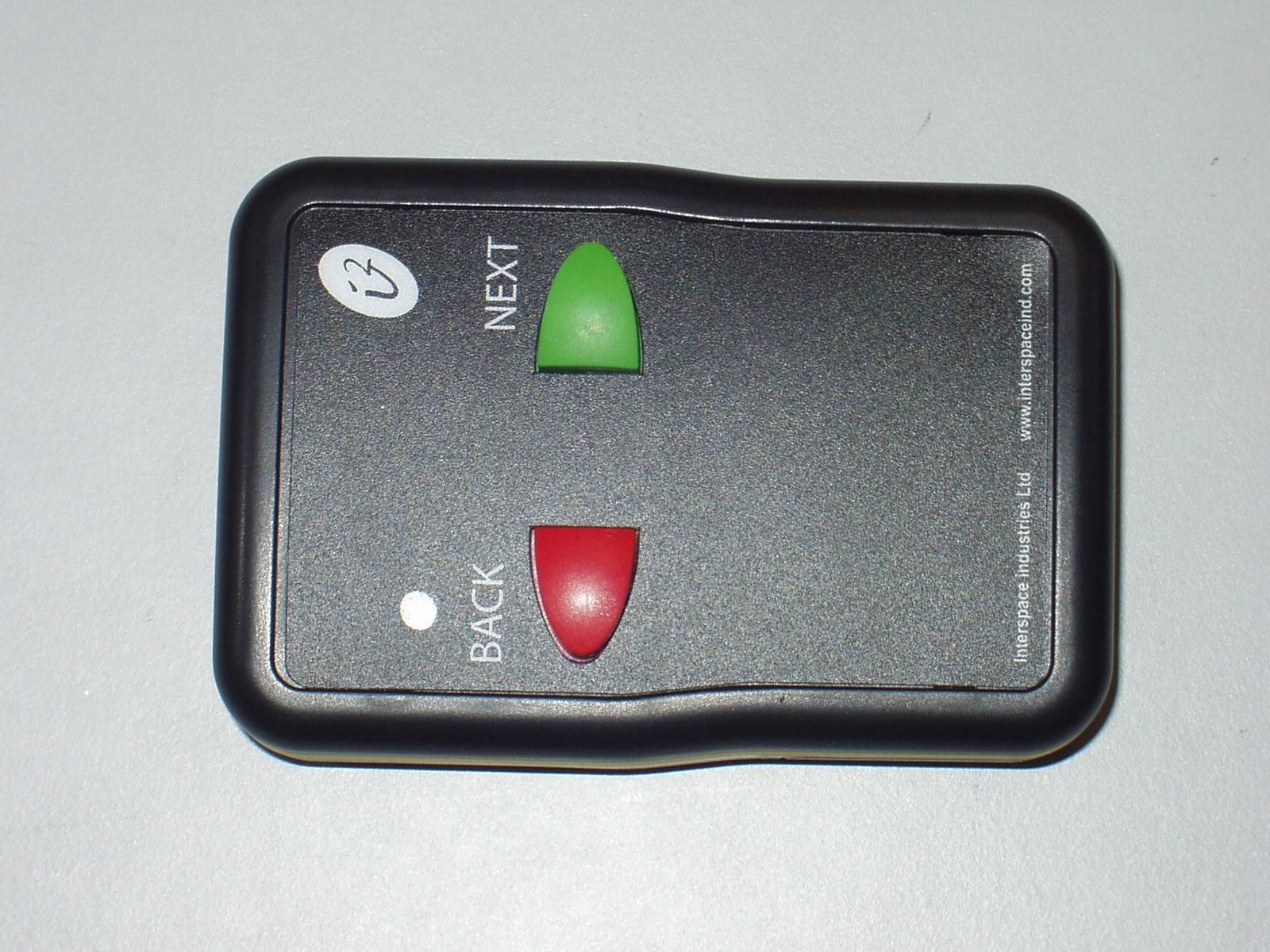
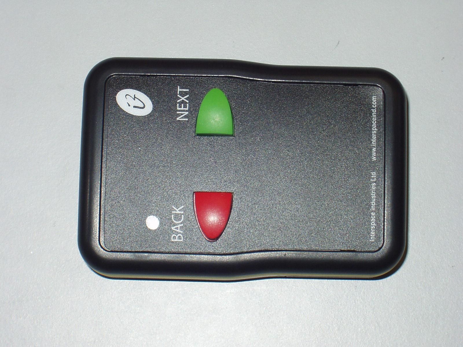
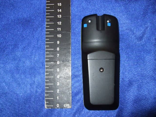
T3Q12TXMasterCue i2TX series handheld cueing transmitter
Hive Industries Limited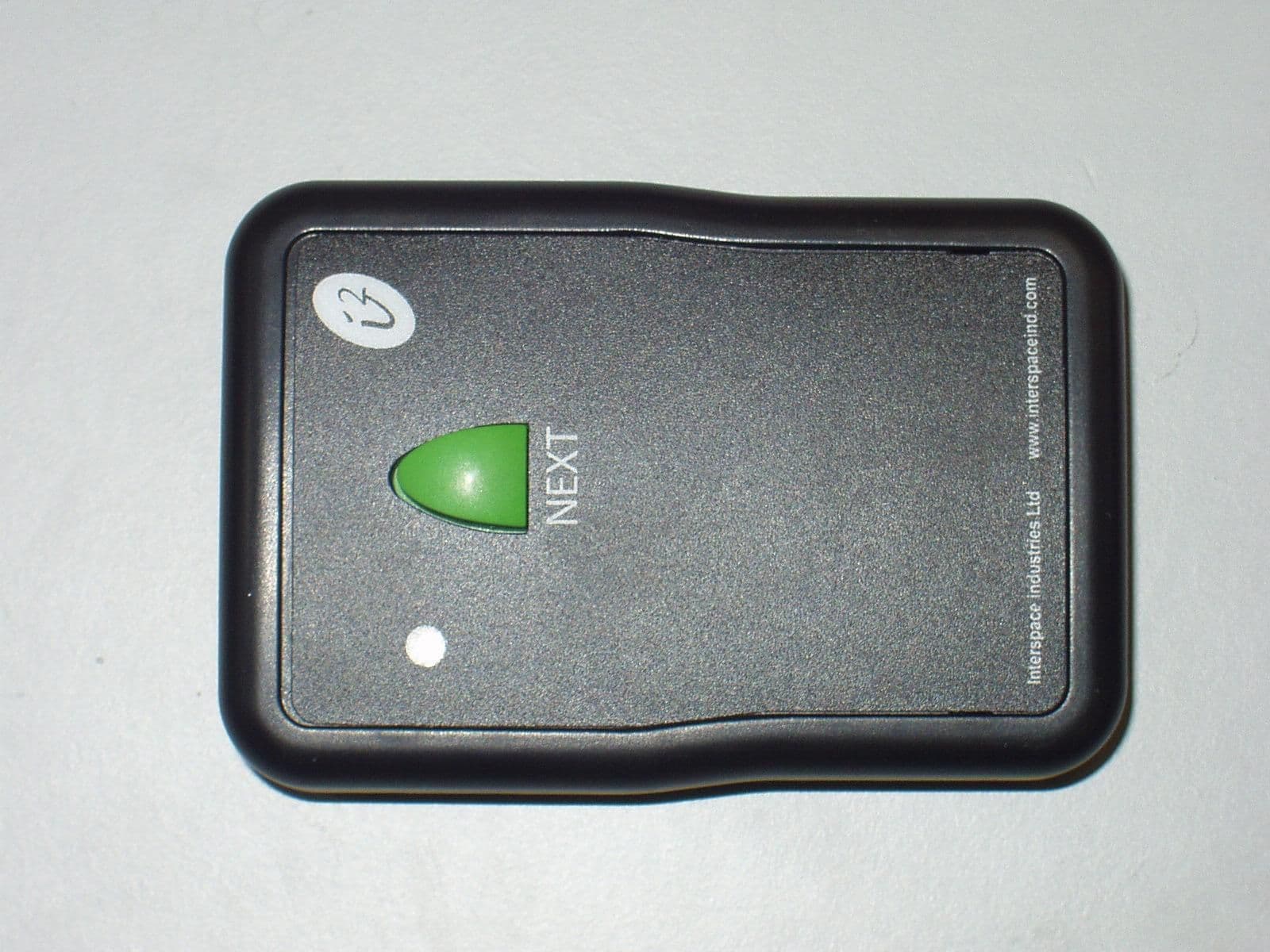
Click to zoom
Application Details
- Equipment Class
- DSC - Part 15 Security/Remote Control Transmitter
- Date of Grant
- Apr 19, 2006
- Application Purpose
- Original Equipment
- Date of Application
- Apr 19, 2006
- Equipment Note
- MasterCue i2TX series handheld cueing transmitter
- Frequency Range
- 434.00700000 - 434.11300000
- Company
- Hive Industries Limited
- Country
- United Kingdom
Documents & Files
Document Text
Text extracted from the exhibit documents filed with the FCC. Open a document above to read the original.
Users Manual
MasterCue V5 USB User Manual interspace industries Cueing and Presentation Control Specialists 2 Contents: Introduction 3 Safety Instructions and FCC 4 Instructions For Use 6 Cable Connections 9 RF System 10 Equipment Supplied 11 Help Line 11 3 Introduction The MasterCue V5 USB is the true professional’s presentation cueing system. Featuring USB interfacing, the MasterCue V5 USB can now connect to computers and directly control PowerPoint presentations as well as providing visual and audible cues. The V5 USB has continued to evolve throughout all MasterCue range models, building on such strengths as the robust case and the AV industrial grade wireless RF system and hard-wired remote controls. With 2 buttons the presenter can request to go backwards if required, or to communicate an alternative presentation function (e.g. go to black or restart). The visual and audible cues are easy to understand and designed to clearly indicate which button has been pushed and what cue action is required. If a production intercom system is being used, the audible cues can be injected into the operators headset using the Comms Loop-through feature. The MasterCue V5 USB is the only choice when a missed cue is just not an option! We hope the MasterCue V5 USB exceeds your expectations and welcome any feedback that you have about this or any of our products. Thank-you The Interspace Industries Team www.interspaceind.com 4 SAFTEY INSTRUCTIONS All the safety and operating instructions should be read before this product is operated and should be retained for further reference. Please adhere to all the warnings on this product and in these operating instructions. Please follow these instructions carefully: Power. Only use the power source indicated on the device. Devices equipped with a grounded plug should only be used with a grounded type outlet. In no way should this grounding be disconnected, modified or suppressed. Power Supply Cord. To unplug the device, do not pull the power supply cord but always the plug itself. The power source outlet should always be near the MasterCue main unit and easily accessible. Ensure the power supply cord cannot be walked on or damaged by items placed on or against it. Do not use if the power supply cord is damaged. Using the device with a damaged power supply cord may expose you to electric shock or other hazards. Check the condition of the power supply cord regularly. Contact your dealer or service centre immediately for a replacement if damaged. Keep Away From Harmful Substances. To prevent the risk of electric shock and fire, do not expose this device to rain, humidity or intense heat sources (such as radiators or direct sunlight). Avoid using this equipment in environments where there is excessive heat, dust, moisture, chemicals, vibration or mechanical shocks. Slots and Openings. These are designed into thedevice for ventilation and to avoid overheating. Always ensure these openings remain clear. Do-not attempt to insert anything into these openings under any circumstances. If liquids have been spilled on, or objects have fallen into, the product it must be checked by a qualified technician before reusing. Connections. All inputs and outputs (except for power input) are TBTS defined under EN60950. • DO NOT OPEN SYSTEM DUE TO HIGH VOLTAGE. • DO NOT IMMERSE IN WATER. If you have any queries regarding these safety instructions or how to maintain the unit please do not hesitate to contact us on +44(0)870 770 8088 Servicing. Do not attempt to service this product yourself. Opening or removing covers and screws may expose you to electric shocks or other hazards. Refer all servicing to qualified service personnel. 5 Federal Communications Commission Handset Transmitters (FCC ID: T3Q I2TX) This device complies with Part 15 of the FCC Rules. Operation is subject to the following two conditions: (1) This device may not cause harmful interference, and (2) this device must accept any interference received, including interference that may cause undesired operation. Main Unit, Receiver Unit and Wired handsets NOTE: This equipment has been tested and found to comply with the limits of a Class B digital device, Pursuant to part 15 of the FCC Rules. These limits are designed to provide reasonable protection against harmful interference in a residential installation. This equipment generates, uses and can radiate radio frequency energy and, if not installed and used in accordance with the instructions, may cause harmful interference to radio communications. However, there is no guarantee that interference will not occur in a particular installation. If this equipment does cause harmful interference to radio or television reception, which can be determined by turning the equipment off and on, the user is encouraged to try to correct the interference by one or more of the following measures: -- Reorient or relocate the receiving antenna. -- Increase the separation between the equipment and receiver. -- Connect the equipment into an outlet on a circuit different from that to which the receiver is connected. -- Consult the dealer or an experienced radio/TV technician for help. Warning ! Any modification or changes made to these devices, unless explicitly approved by Hive Industries, will invalidate the authorisation of the device. Operation of an unauthorised device is prohibited under Section 302 of the Communications Act of 1934, as amended, and Subpart I of Part 2 of Chapter 47 of the Code of Federal Regulations. 6 OPERATING INSTRUCTIONS Unpacking and Connections. Unpack the Main Unit and place on a flat surface within easy access for the Operator. If using the keyboard control please see this separate section also. Main Unit, Receiver Unit and Handsets. Place the RF Receiver Unit behind the stage in close proximity to the wireless handsets being used (not closer than 2metres as signal overloading may occur). Ensure the antenna is vertical. Connect this to the ‘RF in’ input on the MasterCue…
Text truncated - open the document above for the full version.
Attestation Statements
Interspace Industries Ltd, 28 High Street, Arlesey, Bedfordshire. SG15 6RA Tel 0870 770 8088 Fax: 0870 770 8089 email: [email protected] Letter of Agency 2 nd March 2006 TRL Compliance Services Ltd Long Green Forthampton Gloucester GL19 4QH UK To Whom It May Concern: We certify that we are not subject to denial of federal benefits, that includes FCC benefits, pursuant to Section 5301 of the Anti-Drug Abuse ACT of 1988, U.S.C. 862. Further, no party, as defined in 47 CFR 1.2002(b), to the application is subject to denial of federal benefits, that includes FCC benefits. Thank you for your attention to this matter. Thank you for your attention to these matters. Yours faithfully Hive Industries Limited 28 High Street Arlesey SG15 6RA UK Dave Humphrys Managing Director
Block Diagram
voltage regulation 9V battery transmitter (PLL crystal oscillator). 434.075 MHz. controller press buttons 4
Cover Letter(s)
Interspace Industries Ltd, 28 High Street, Arlesey, Bedfordshire. SG15 6RA Tel 0870 770 8088 Fax: 0870 770 8089 email: [email protected] Request for Confidentiality In Accordance with FCC Rule 0.459 2 nd March 2006 TRL Compliance Services Ltd Long Green Forthampton Gloucester GL19 4QH UK RE: Certification Application FCC ID: T3Q I2TX To Whom It May Concern: Please be advised that the following information is to be held confidential on behalf of Hive Industries Limited. • Schematic diagrams • Photographs of internal component layout • Parts list (BOM) The application contains technical information which Hive Industries Limited deems to be trade secrets and propriety. If made public, the information might be used to the disadvantage of the applicant in the market place. Thank you for your attention to this matter. Yours faithfully Hive Industries Limited 28 High Street Arlesey SG15 6RA UK Dave Humphrys Managing Director
ID Label/Location Info
Interspace Industries Ltd, 28 High Street, Arlesey, Bedfordshire. SG15 6RA Tel 0870 770 8088 Fax: 0870 770 8089 email: [email protected] FCC Labelling Requirements and Information 2 nd March 2006 TRL Compliance Services Ltd Long Green Forthampton Gloucester GL19 4QH UK RE: FCC Labelling Requirements FCC ID: T3Q I2TX The following label information is required by the FCC Rules and Regulations for certified devices. Also attached, please find marketing information required by the FCC Rules and Regulations. Thank you for your attention to these matters. Yours faithfully Hive Industries Limited 28 High Street Arlesey SG15 6RA UK Dave Humphrys Managing Director Interspace Industries Ltd, 28 High Street, Arlesey, Bedfordshire. SG15 6RA Tel 0870 770 8088 Fax: 0870 770 8089 email: [email protected] Interspaceinid.com Part Id i2TX-3 Serial No. 130 16 0000 FCC ID T3QI2TX interspaceind.com Interspaceinid.com Part Id i2TX-2 Serial No. 130 16 0000 FCC ID T3QI2TX interspaceind.com Interspaceinid.com Part Id i2TX-1 Serial No. 130 16 0000 FCC ID T3QI2TX interspaceind.com
Operational Description
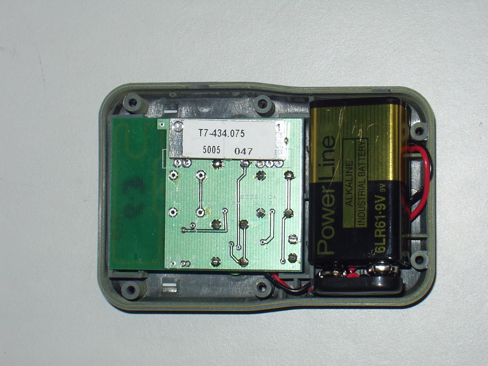
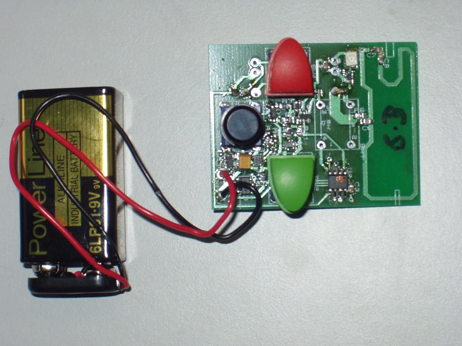
Introduction. The i2TX-1, i2TX-2 and i2TX-3 are hand held transmitters for use with the MasterCue V5 and compatible systems. They are all identical, except for the number of switches / buttons fitted (the last digit of the model number indicates the number of buttons). The same circuit board is used for all 3 models. The board has 4 positions in total although no four button model exists currently. Overview. The MasterCue V5 USB is the true professional’s presentation cueing system. Featuring USB interfacing, the MasterCue V5 USB can now connect to computers and directly control PowerPoint presentations as well as providing visual and audible cues. The V5 USB has continued to evolve throughout all MasterCue range models, building on such strengths as the robust case and the hard-wired remote controls. i2TX-3 hand held transmitters. If a production intercom system is being used, the audible cues can be injected into the operators headset using the Comms Loop-through feature. Transmitter detail. The transmitter is operated from a standard 9V alkaline battery. Button presses are recognised by simple control circuitry and a PIC is used to turn the transmitter on and off with a short message. The PIC limits the number of messages so that if a button is held down, transmission stops within 5 seconds. The transmitter is an OEM SIL chip which contains a Phase Locked Loop using a crystal oscillator tuned to 434.075 MHz. CMOS data presented to the OEM chip is (when enabled) transmitted at 434.074 MHz using FM. The antenna is part of the PCB using a loop design with added capacitance for matching/tuning and in line resistance to limit power of the wanted transmissions.
Test Report
File name HIVE.087 PAGE 1 OF 38 QMF21 – 8: FCC PART 15 ISSUE 02: - APR 06 FCC Test Report for MasterCue V5 USB i2TX1, i2TX2, i2TX3 Report Number 03-087/3051/6/06A Supersedes Report Number 03-087/3051/6/06 Report Produced by: - R.N. Electronics Ltd. 1 Arnolds Court Arnolds Farm Lane Mountnessing ESSEX CM13 1UT www.rnelectronics.com Telephone 01277 352219 Facsimile 01277 352968 EMC & RADIO TEST SERVICES S RN Electronics ©2004 RN ELECTRONICS LIMITED REPORT NUMBER 03-087/3051/6/06A ALL RIGHTS RESERVED File name HIVE.087 PAGE 2 OF 38 QMF21 – 8: FCC PART 15 ISSUE 02: - APR 06 1. Contents 1. CONTENTS............................................................................................................................................ 2 2. SUMMARY OF TEST RESULTS............................................................................................................... 3 3. INFORMATION ABOUT EQUIPMENT UNDER TEST................................................................................ 4 4. SPECIFICATIONS.................................................................................................................................... 4 5. TESTS, METHODS AND RESULTS.......................................................................................................... 5 5.1 Conducted Emissions ............................................................................................................5 5.2 Radiated Emissions ............................................................................................................... 6 5.3 Intentional Radiator Field Strength ....................................................................................... 7 5.4 Frequency Tolerance .............................................................................................................8 5.5 Duty Cycle............................................................................................................................ 9 5.6 Maximum Spectral Power Density ...................................................................................... 10 5.7 20dB Bandwidth..................................................................................................................11 6. PLOTS AND RESULTS.......................................................................................................................... 12 6.1 Conducted Emissions .......................................................................................................... 12 6.2 Radiated Emissions .............................................................................................................13 6.3 Fundamental Emissions ....................................................................................................... 27 6.4 Duty Cycle........................................................................................................................... 28 6.5 Maximum Spectral Power Density ...................................................................................... 29 6.6 Modulation Bandwidth ........................................................................................................ 30 7 Explanatory Notes ...............................................................................................................31 7.1 Explanation of FAIL LIMIT 1 Statement............................................................................ 31 7.2 Explanation of limit line calculations for radiated measurements ....................................... 31 8. PHOTOGRAPHS.................................................................................................................................... 32 9. SIGNAL LEADS.................................................................................................................................... 34 10. TEST EQUIPMENT CALIBRATION LIST................................................................................................ 35 11. AUXILIARY EQUIPMENT..................................................................................................................... 36 11.1 Auxiliary equipment supplied by Hive Industries ............................................................... 36 11.2 Auxiliary equipment supplied by RN Electronics Limited.................................................. 36 12. MODIFICATIONS................................................................................................................................. 37 13. Compliance information................................................................................................... 38 ©2004 RN ELECTRONICS LIMITED REPORT NUMBER 03-087/3051/6/06A ALL RIGHTS RESERVED File name HIVE.087 PAGE 3 OF 38 QMF21 – 8: FCC PART 15 ISSUE 02: - APR 06 2. Summary of Test Results The MasterCue V5 USB, i2TX-3 was tested to the following standards: - FCC Part 15C (effective date February 16, 2006); Class DSC Intentional Radiator Title Reference Results 1. Conducted Emissions FCC Part 15C §15.207 NOT APPLICABLE¹ 2. Radiated Emissions FCC Part 15C §15.205, §15.209 & §15.231 PASSED 3. Modulation Bandwidth FCC Part 15C §15.215(c), §15.231 PASSED 4. Intentional Radiator Field Strength FCC Part 15C §15.231 PASSED 5. Frequency Tolerance FCC Part 15C NOT APPLICABLE² 6. Duty Cycle FCC Part 15C §15.231 PASSED 7. Power Spectral Density FCC Part 15C NOT APPLICABLE² 8. Frequency separation FCC Part 15C NOT APPLICABLE² 9. No. of hopping channels FCC Part 15C NOT APPLICABLE² 10. Input power FCC Part 15C NOT APPLICABLE² 11. Sweep repetition rate FCC Part 15C NOT APPLICABLE² ¹ Equipment Under Test battery powered. ² No particular limits specified. Date of Test:6th & 9th March 2006 Test Engineer: Approved By: Customer Representative: ©2004 RN ELECTRONICS LIMITED REPORT NUMBER 03-087/3051/6/06A ALL RIGHTS RESERVED File name HIVE.087 PAGE 4 OF 38 QMF21 – 8: FCC PART 15 ISSUE 02: - APR 06 3. Information about Equipment Under Test Manufacture of EUT Hive Indu…
Text truncated - open the document above for the full version.
Contact Information
Applicant
Dave Humphrys(CEO)
Technical Contact
Hive Industries LimitedDave Humphrys
[email protected]+44 8707708088
28 High Street · Bedfordshire · United Kingdom
Test Firm
R N Electronics LtdSue Ray
Technical Specifications
| # | Rule Parts | Frequency Range | Power Output | Emission |
|---|---|---|---|---|
| 1 | 15.231 | 434.007 MHz - 434.113 MHz | - | 110KF1D |
Other Applications from Hive Industries Limited
T3QI2TXL
Dec 21, 2011MasterCue I2TX-L series handheld cueing transmitter
Equipment Class
DSC - Part 15 Security/Remote Control Transmitter