FCCID.CO- FCC ID Database
HomeCompaniesEquipment ClassesSearch

© 2026 FCC ID Database. All rights reserved.

AboutContactData sourced from FCC public records
  1. Home/
  2. Bentley Kinetics, Inc./
  3. T4E-KSENS401

T4E-KSENS401KSensor

Bentley Kinetics, Inc.
KSensor - FCC ID T4E-KSENS401 - Bentley Kinetics, Inc.
Click to zoom

Application Details

Equipment Class
DTS - Digital Transmission System
Date of Grant
Apr 17, 2006
Application Purpose
Original Equipment
Date of Application
Apr 17, 2006
Equipment Note
KSensor
Frequency Range
2404.00000000 - 2480.00000000
Company
Bentley Kinetics, Inc.
Country
United States

Documents & Files

Select a file to view

Users Manual

↗

Cover Letter(s)

↗
↗

External Photos

↗

ID Label/Location Info

↗

Internal Photos

↗

Operational Description

↗

RF Exposure Info

↗

Test Report

↗

Test Setup Photos

↗

Document Text

Text extracted from the exhibit documents filed with the FCC. Open a document above to read the original.

Users Manual

Getting Started with K-VEST™ Version 1.0 March 2006 Version 1.0 Getting Started with K-VEST™ ii www.K-VEST.com Copyright © 2006 Bentley Kinetics, Inc. The information in this Document is the intellectual property of Bentley Kinetics, Inc. This Document may not be reproduced in whole or in part, by any means, without the written consent of Bentley Kinetics, Inc. All Rights Reserved. The Software described in this Document and all copies of the Software are the property of Bentley Kinetics, Inc. The Software is provided under a license agreement containing restrictions on use and disclosure. The software contains trade secrets of Bentley Kinetics, Inc. Reverse engineering of the Software is prohibited. If provided to the U.S. Government, this Software and this Document are provided with Res- tricted Rights. Use, duplications, or disclosure by the Government is subject to restrictions set forth in FAR 52-227-19 (c) (2) (June 1987) or DOD FAR Supplement 252.227-7013 (c) (1) (ii) (June 1988) or the NASA FAR Supplement as applicable. Contractor/Manufacturer is Bentley Kinetics, Inc. Trademarks K-VEST, KINESYNC, K-SENSOR, K-FACTOR, Bentley Kinetics, the Bentley Kinetics logo, and the K-VEST logo are trademarks of: Bentley Kinetics, Inc. 49 Constitution Dr. Bedford, NH 03110 603.472.3519 All other product and company names mentioned in this document are trademarks or registered trademarks of their respective companies or organizations. Regulatory Statements and Approvals FCC Statements: This device complies with part 15 of the FCC Rules. Operation is subject to the following two conditions: (1) This device may not cause harmful interference, and (2) This device must accept any interference received, including interference that may cause undesired operation. Caution: changes or modifications not expressly approved by the party responsible for compliance could void the user’s authority to operate the equipment. Getting Started with K-VEST™ Version 1. 0 www.K-VEST.com iii NOTE: This equipment has been tested and found to comply with the limits for a Class B digital device, pursuant to part 15 of the FCC Rules. These limits are designed to provide reasonable protection against harmful interference in a residential installation. This equipment generates, uses and can radiate radio frequency energy and, if not installed and used in accordance with the instructions, may cause harmful interference to radio communications. However, there is no guarantee that interference will not occur in a particular installation. If this equipment does cause harmful interference to radio or television reception, which can be determined by turning the equipment off and on, the user is encouraged to try to correct the interference by one or more of the following measures: —Reorient or relocate the receiving antenna. —Increase the separation between the equipment and receiver. —Connect the equipment to an outlet on a circuit different from that to which the receiver is connected. —Consult the dealer or an experienced radio/TV technician for help. Canada - Industry Canada (IC) This Class B digital apparatus meets all requirements of the Canadian Interference-Causing Equipment Regulations. cet appareil de la class B respecte toutes les exigences du Reglement sur le matereil brouiller du Canada. Europe - European Union Notice All products with the CE marking comply with the EMC Directive (89/336/EEC) and the Low Voltage Directive (73/23/EEC) issued by the Commission of the European Community. Compliance with these directives implies conformity to the following European Norms (in brackets are the equivalent international standards). • EN 55022 (CISPR 22) - Electromagnetic Interference • EN 55024 (IEC61000-4-2,3,4,5,6,8,11) - Electromagnetic Immunity • EN 61000-3-2 (IEC610000-3-2) - Power Line Harmonics • EN 61000-3-3 (IEC610000-3-3) - Power Line Flicker • EN 60950 (IEC60950) - Product Safety Products labeled with the CExxxx or the CE alert marking contain a radio transmitter that complies with the R&TTE Directive (1999/5/EC) issued by the Commission of the European Community. Compliance with this directive implies conformity to the following European Norms (in brackets are the equivalent international standards). • EN 60950 (IEC60950) - Product Safety • EN 300 328 Technical requirements for radio equipment. • ETS 300 893 and ETS 301 489-17 General EMC requirements for radio equipment. • ETS 301489-1 To determine the type of transmitter, check the identification label on your Product. Version 1.0 Getting Started with K-VEST™ iv www.K-VEST.com Precautionary Statements Any changes or modifications to any K-SENSOR™ unit or K-SENSOR™ wireless receiver not expressly approved by Bentley Kinetics will void the warranty and any regulatory compliance issued for the system. Do not drop or otherwise shock the K-SENSOR™ units, because they can be permanently damaged. Do not bend, twist, pull strongly or tamper in any way with any part of the cabling on the K-SENSOR™ wireless receiver. Take care to avoid electric shocks. Do not plug-in or unplug the charging cable with wet hands. Getting Started with K-VEST™ Version 1. 0 www.K-VEST.com v Contents Introduction 6 Installing KINESYNC™ 7 Pre-Installation Check List 7 Running the Software Installation Program 8 Equipment Setup 9 Equipment Inventory 9 Setting Up the Laptop and Camera Stand 10 Put on the K-VEST and Sensors 12 Putting on the K-VEST 13 Using KINESYNC 15 Starting the KINESYNC Software 15 KINESYNC Shortcut Keys 17 Checking the Sensors 17 Calibrating the Sensors 17 Capturing Your First Swing 19 Analysis Overview 19 Roadmap of the KINESYNC Display 19 Getting Help 20 Try a Simple Exercise 20 Ending a Session 21 Exiting KINESYNC 21 Recharging the Sensors 21 More Information 22 Version 1.0 Getting Started with K-VEST™ 6 www.K-VEST.com Introduction K-VEST™ is a professional-level swing analysis and training system that integrates state-of-the-art wireless technology with software to give y…

Text truncated - open the document above for the full version.

Cover Letter(s)

Attn:Reviewing Engineer Federal Communications Commission 7435 Oakland Mills Road Columbia, MD 21046 RE: LETTER OF AGENT AUTHORIZATION To Whom It May Concern: We, the undersigned, hereby authorize MET Laboratories, Inc. to act on our behalf in all matters relating to application for equipment authorization, including the signing of all documents relating to these matters. We also hereby certify that no party to the application authorized hereunder is subject to the denial of benefits, including FCCbenefits, pursuant to Section 5301 of the Anti-Drug Abuse Act of 1988, 21 U.S.C.853(a). This agreement expires one year from the current date. Sincerely, March 23, 2006 Bill Nawn VP Operations

Cover Letter(s)

Attn:Reviewing Engineer Federal Communications Commission 7435 Oakland Mills Road Columbia, MD 21046 RE: CONFIDENTIALITY REQUEST FORFCC ID T4E-KSENS401 To Whom It May Concern: This letter serves as an official request for confidentiality under FCCRule Section 0.459. We have requested that theschematic diagrams, block diagrams and parts listsrequired tobe submitted with this application be withheld from public review.The documents are company proprietary information thatisnever publicly disclosed. Please contact me if there is any information you may need. Please contact me if there is any information you may need. Sincerely, March 23, 2006 Bill Nawn VP Operations

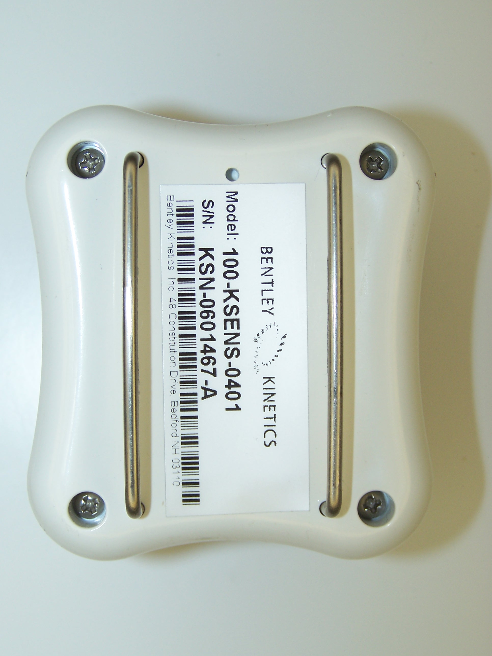
ID Label/Location Info

Bentley Kinetics KSensor FCC Label Bottom of KSensor

Operational Description

Proprietary Information KSensor Operational/ Technical Description 1.Overview: TheKSensor is a wirelessinertial sensingdevice.The system is used to detect the orientation of an object that the inertial sensor is attached to. The sensor uses gyros, accelerometers and magnetometers to detect its yaw, pitch and roll. Typical uses are for sports training, virtual reality applications and simulation and training. 2.Technical Description TheKSensor usesa transceiver based on a Chipcon Zigbee chipset but it does not implement the higher level Zigbee software protocol stack. There arethreeboards in the receiver package. The first is the radio board that has the Chipcon radio chip, a Pic microprocessor to handle the communicationprotocolbetween theIMUand the Chipcon chip and a PCB antenna. The second board isthe IMU board with a processor and the gyros, accels and magnetometers along with necessary support chips. The final board has the power switch and charger circuit for the battery. The Chipcon 2420 radio used is a single chip Direct Sequence Spread Spectrum (DSSS) transceiver. Its supports data rates up to 250kbps with a 2 MChip/s chip rate. It uses O- QPSK with half sine pulse shaping modulation.The 2420 uses aninput reference oscillatorof16MHz. Theintegrated PCB antenna is a so-called Inverted-F type. The Inverted F antenna is a wire monopole where the top section is folded down to be parallel with the ground plane. The peak antenna gain is 5 dBi, the corresponding peak field strength is 90dBuV/m. PC ReceiverKSensor Gyros Accels Mags Proprietary Information There is a balum to convert output of the chip to the single ended input of the PCB antenna. The system does not do frequency hopping. It supports up to 16 channels spaced at 5Mhz intervals between 2.4 and 2.4835 MHz.

RF Exposure Info

MPE Limit Calculation: EUT’s lowest frequency channel @ 2400 MHz; Limit for Uncontrolled exposure: 1 mW/cm 2 Equation from page 18 of OET 65, Edition 97-01 S = PG / 4πR 2 where, S = Power Density mW/m 2 P = Power Input to antenna mili Watts G = Numeric Antenna Gain R = Distance to the center of radiation of the antenna (20 cm for Mobile minimum distance) Antenna Numeric Gain = 10 dBi/10 Power at antenna port = 0.297 mW Antenna Gain = 5 dBi Numeric antenna gain = 10 5/10 = 3.16 S = (0.297)(3.16) / 4(3.1416)(20) 2 S = 0.000187 mW/cm 2 Therefore EUT meets the Uncontrolled Exposure limit.

Test Report

MET Laboratories, Inc. Safety Certification - EMI - Telecom Environmental Simulation 914 WEST PATAPSCO AVENUE ! BALTIMORE, MARYLAND 21230-3432 ! PHONE (410) 354-3300 ! FAX (410) 354-3313 The Nation’s First Licensed Nationally Recognized Testing Laboratory April 17, 2006 Bentley Kinetics 60 Rogers Street Manchester, NH 03103 Dear Bill Nawn, Enclosed is the EMC test report for compliance testing of the Bentley Kinetics, KSensor IMU400 as tested to the requirements of Title 47 of the CFR, Part 15 Subpart B for a Class B Digital Device and Subpart C, §15.247 for Intentional Radiators. Thank you for using the services of MET Laboratories, Inc. If you have any questions regarding these results or if MET can be of further service to you, please feel free to contact me. Sincerely yours, MET LABORATORIES, INC. Molly Sunderland Documentation Department Reference: (\Bentley Kinetics\ KSensor IMU400 \ EMC19336A-FCC247) Certificates and reports shall not be reproduced except in full, without the written permission of MET Laboratories, Inc. While use of the National Voluntary Laboratory Accreditation Program (NVLAP) letters or the NVLAP Logo, the Standards Council of Canada Logo, A2LA, or the Nationally Recognized Testing Laboratory (NRTL) Letters in this report reflects MET Accreditation under these programs, these letters, logo, or statements do not claim product endorsement by these organizations or any Agency of the U.S. Government. This letter of transmittal is not a part of the attached report. DOC-EMC702 2/26/2004 MET Laboratories, Inc. Safety Certification - EMI - Telecom Environmental Simulation 914 WEST PATAPSCO AVENUE ! BALTIMORE, MARYLAND 21230-3432 ! PHONE (410) 354-3300 ! FAX (410) 354-3313 DOC-EMC702 2/26/2004 Certificates and reports shall not be reproduced except in full, without the written permission of MET Laboratories, Inc. Electromagnetic Compatibility Test Report For the Bentley Kinetics KSensor IMU400 Tested in Accordance with Title 47 of the CFR FCC Part 15 Subpart B and C MET Report: EMC19336A-FCC247 April 17, 2006 Prepared For: Bentley Kinetics 60 Rogers Street Manchester, NH 03103 Prepared By: MET Laboratories, Inc. 914 West Patapsco Avenue Baltimore, MD 21230 Bentley Kinetics KSensor IMU400 CFR Title 47, Part 15 Subpart B and C MET Report EMC19336A - FCC247 © 2006, MET Laboratories, Inc. Page i of v DOC-EMC702 2/26/2004 Electromagnetic Compatibility Test Report For the Bentley Kinetics KSensor IMU400 Tested in Accordance with Title 47 of the CFR FCC Part 15 Subpart B and C Dusmantha Tennakoon Molly Sunderland Test Engineer, Electromagnetic Compatibility Lab Documentation Department Engineering Statement: The measurements shown in this report were made in accordance with the procedures indicated, and the emissions from this equipment were found to be within the limits applicable. I assume full responsibility for the accuracy and completeness of these measurements, and for the qualifications of all persons taking them. It is further stated that upon the basis of the measurements made, the equipment tested is capable of operation in accordance with the requirements of Part 15, §15.247 of the FCC Rules under normal use and maintenance. Kevin Mehaffey Manager, Electromagnetic Compatibility Lab Bentley Kinetics KSensor IMU400 CFR Title 47, Part 15 Subpart B and C MET Report EMC19336A - FCC247 © 2006, MET Laboratories, Inc. Page ii of v DOC-EMC702 2/26/2004 Report Status Sheet Revision Report Date Reason for Revision Ø April 17, 2006 Initial Issue. Bentley Kinetics KSensor IMU400 CFR Title 47, Part 15 Subpart B and C MET Report EMC19336A - FCC247 © 2006, MET Laboratories, Inc. Page iii of v DOC-EMC702 2/26/2004 List of Terms and Abbreviations AC Alternating Current ACF Antenna Correction Factor Cal Calibration d Measurement Distance dB Deci Bels dBFV Deci-Bels above one micro Volt dBFV/m Deci-Bels above one micro Volt per meter DC Direct Current DCF Distance Correction Factor E Electric Field EUT Equipment Under Test f Frequency FCC Federal Communications Commission H Magnetic Field GHz Giga Hertz Hz Hertz ICES Interference-Causing Equipment Standard kHz kilohertz kPa kilopascal kV kilo Volt LISN Line Impedance Stabilization Network MHz MegaHertz FH micro Henry FF micro Farad Fs micro seconds RF Radio Frequency RMS Root-Mean-Square Bentley Kinetics KSensor IMU400 CFR Title 47, Part 15 Subpart B and C MET Report: EMC19336A - FCC247 © 2006, MET Laboratories, Inc. Page iv of vi DOC-EMC702 2/26/2004 Table of Contents 1 Introduction .....................................................................................................................................................................1 1.1 Overview.....................................................................................................................................................................1 1.2 Test Site ......................................................................................................................................................................1 1.3 Testing Summary ........................................................................................................................................................2 2 Equipment Configuration...............................................................................................................................................3 2.1 Description of EUT .....................................................................................................................................................3 2.2 Equipment Configuration............................................................................................................................................3 2.3 Support Equipment .....................................................................................................................................................4 2.4 Ports and Cabling Information ..........................................................…

Text truncated - open the document above for the full version.

Contact Information

Applicant

Bill Nawn(VP of Operations)
[email protected]603-472-3519Fax: 603-472-3539

Test Firm

EUROFINS ELECTRICAL AND ELECTRONIC TESTING NA, INCGreg Kovolenko
[email protected]4108444071Fax: 4103543313

Technical Specifications

#Rule PartsFrequency RangePower OutputEmission
115C2.40 GHz - 2.48 GHz297.00 µW1M70F2D
Confidentiality
Long Term
Grant Notes
Power Output Listed is peak Conducted.

Other Applications from Bentley Kinetics, Inc.
KSemsor- IC3 - FCC ID T4E-KSENS201 - Bentley Kinetics, Inc.
T4E-KSENS201

KSemsor- IC3

Apr 17, 2006

Equipment Class

DTS - Digital Transmission System