T4ICCB110SCA FM Convertor
UNIGOLD INDUSTRIAL COMPANY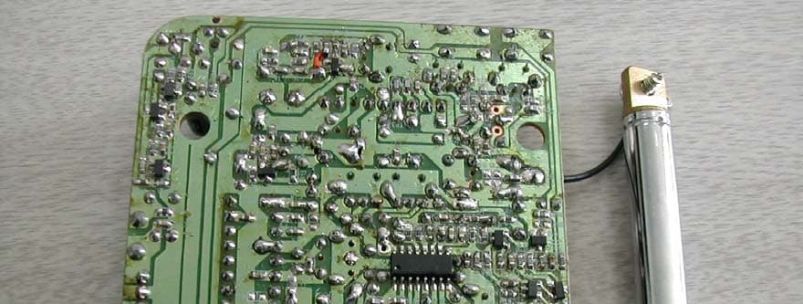
Click to zoom
Application Details
- Equipment Class
- DXT - Part 15 Low Power Transceiver, Rx Verified
- Date of Grant
- May 24, 2006
- Application Purpose
- Original Equipment
- Date of Application
- May 23, 2006
- Equipment Note
- SCA FM Convertor
- Frequency Range
- 106.70000000 - 107.90000000
- Company
- UNIGOLD INDUSTRIAL COMPANY
- Country
- China
Documents & Files
Document Text
Text extracted from the exhibit documents filed with the FCC. Open a document above to read the original.
Cover Letter(s)
ADT (Shanghai) Corporation 2F, Building C, No.1618, Yishan Rd., 201103, Shanghai, China Apr. 5, 2006 FCC ID: T4ICCB110 The following lists are the answers for the comments on Apr. 4, 2006, please kindly have a review on it: 1) Operational description cites frequencies from 87.7 – 88.9. Tunable frequencies of 87.7 and 87.9 are not allowed under FCC Part 15. Please explain. RE: Please see Operational Description_0405 and User manual_0405. 2) Please explain what keeps the device from transmitting on channels 88.7 and 88.9 to be in compliance 15.15. RE: Please see Operational Description_0405 and User manual_0405. 3) Type of device on the 731 form appears to be a DXT. Please correct. RE: Please see 731 form_0405. 4) Label exhibit should also show placement of the label on the device. Please provide additional information as necessary. RE: Please see Label_0405. 5) It is uncertain what the exact purpose of this device is....What is the RX frequency? Why retransmission of an FM signal? Please note that information regarding SCA receivers state that SCA receivers may not be tunable. Please explain. RE: The RX frequency is 94.9MHz 6) Please explain the difference between peak and average readings. It appears the raw data is the same, but the results are different. RE: Please see test report_0405. 7) The fundamental results appear to be the same frequency on channel 6 and 12. Please review. RE: Please see test report_0405. 8) Please explain what type of signal was broadcast to the device to RX for purposes of this testing. Thank you very much.
Cover Letter(s)
ADT (Shanghai) Corporation 2F, Building C, No.1618, Yishan Rd., 201103, Shanghai, China Apr. 6, 2006 FCC ID: T4ICCB110 The following lists are the answers for the comments on Apr. 5, 2006, please kindly have a review on it: 1) It is still not clear what keeps the device from transmitting on channels 87.7 and 87.9. Note that the rotary dial has several positions marked “-“ that were likely used for these previously for these 2 channels. Can you explain what the device does if the dial is positioned in either of the “-“ positions. RE: When choosing the transmitting frequency, the product is powered off. It can be powered on only in the condition that the usable transmitting frequency is clearly selected. The transmitting frequencies which marked as “-“ in diagram D of user manual are restricted to be used and are forbidden to put them under power-on statement. 2) The new test report removed all peak data. Please note that compliance to both peak and average limits must be shown. Previously different results for peak and average where provided, but it appeared the same raw data was identical. Please review/correct. RE: Please see test report_0406. 3) It is uncertain what the exact purpose of this device is....What is the RX frequency? Why retransmission of an FM signal? Please note that information regarding SCA receivers state that SCA receivers may not be tunable. Please explain. RE: The broadcast station main frequency channel 94.9Mhz,sub carrier frequency 67Khz then unit apply RX 94.9Mhz, the SCA signal is audio signal modulation on sub carrier 67Khz frequency range, and then 67Khz sub carrier frequency modulation on main frequency 94.9Mhz. 4) Please explain what type of signal was broadcast to the device to RX for purposes of this testing. RE: SCA channel is fixed frequency channel, some body want to use on car but don’t want to changed the famous name original car radio (no famous name supplier to made SCA car radio) only one way to used car adaptor to instead of replace car radio. When user install with SCA car adaptor and reception with SCA signal, original car radio without SCA signal decoder, must to use SCA adaptor to decode the SCA signal (sub carrier frequency) and after convert to FM band frequency and signal to car radio reception. Some times the local broadcasting station already assign broadcast signal in adaptor transmit frequency location. Then user must little bit shift the transmit frequency to empty broadcast station frequency position, the final design on FM band low end with 5 frequency channel, high end with 7 frequency channel for user shift purpose. Thank you very much.
Cover Letter(s)
ADT (Shanghai) Corporation 2F, Building C, No.1618, Yishan Rd., 201103, Shanghai, China Apr. 18, 2006 FCC ID: T4ICCB110 The following lists are the answers for the comments on Apr. 11, 2006, please kindly have a review on it: 1) FYI....Information regarding 87.7 and 87.9 is sufficient to show how the device stops transmitting is sufficient. RE: Please see circuitry information and Schematics. 2) However device apparently required modifications to meet this requirement (1 given above) and this sample does not appear to have been evaluated. Please note that the FCC expects all data submitted to be in support of final device. How does the changes affect the characteristics of the device? Note that relayout issues and additional circuits could affect spurious emissions. This and any other tests deemed relevant because of the changes needs to be evaluated and also new internal photographs provided for final device given the device is modified/changed. RE: The modified device is on a delivery now. We’ll submit the updated report as soon as possible. 3) Was final manual provided per my last email which suggested to take out the language that was added for 87.4 and 87.9 MHz. Please correct. RE: Please see user manual. 4) There is one additional item which we are researching and contacting the FCC in regards to this.....Please note that historically, the FCC has only allowed "repeater" type of operations under part 15 if the device meets the following: The TX must have the ability to determine the source and validity of the incoming signal, and only retransmits signals from a specific transmitter. In other words, it only transmits when it demodulates and decodes (and validates) an incoming signal from the specific transmitter. Please comment on if this device is capable of this. It appears that the device will always transmit, even in absence of an incoming signal. Please explain. In the mean time we are also investigating directly with the FCC as well to see if this requirement can be waived in this case. To our knowledge, waiving of this requirement has only been done 1 time by the FCC. RE: The converter only reception fixed frequency broadcast station and decode signal output to audio signal through transmitter transmit FM frequency signal (transmitter transmit range around 3 meter from car compartment to same car “car antenna”.) The device power on after, transmitter portion always with operation even income audio signal off. 5) FYI....We are still in communication with the FCC. They are asking some questions that they want answered prior to use issuing the certificate on this device. Thank you very much.
Cover Letter(s)
Mr. Johnson, While we believe that most issues involving Part 15 devices are squarely within the jurisdiction of the Office of Engineering and Technology, we are not aware of any rules in Part 15 that prevent this type of operation. I hope this helps, Jim Bradshaw Deputy Chief Audio Division Media Bureau *** Non-Public: For Internal Use Only *** -----Original Message----- From: Timothy R. Johnson [mailto:[email protected]] Sent: Tuesday, April 11, 2006 4:31 PM To: James Bradshaw; Joe Dichoso; Joe Dichoso Subject: RE: Response to Inquiry to FCC (Tracking Number 184756) Jim, First, this device is only rebroadcasting the SCA feed so that the SCA feed is receivable on a standard RX on an open channel selectable by the user. While we have not yet heard back from the Media Bureau in regards to your earlier comments. Please note that some good information regarding SCA carriers may be found at: http://www.fcc.gov/mb/audio/subcarriers/ near the bottom of the page. Note that it appears that SCA transmissions as part of the FM licensing has been deregulated some years ago. However, according to this site, only fixed frequency receivers are allowed (you can not use tunable for the RX portion). We have already confirmed this device is a fixed frequency RX only at 94.9 MHz. The user may select one of 12 channels between 88.1 - 88.9 MHz & 106.7 - 107.9 MHz. Please note that our main question below is in regards to requiring the device to demodulate and verify before retransmitting. We are still awaiting information from the applicant on this, but my first impression from my review is that the device appears to not shut off in absence of RX the 94.9 MHz signal. Therefore we are asking if this would still be allowed if it does not demodulate and verify prior to retransmitting. The FCC did allow a special case for us last year that down converted satellite radio to 902-928 MHz frequencies without demodulation and verification. The FCC allowed special permission of this under 15.249 (partially because of lower power levels) but not under 15.247. We are wondering if a similar situation exists here because of the very low power levels involved with 15.237 and the single RX frequency involved. Please comment. Given the power levels under 15.237 and the fact that the you are allowed fixed frequency receivers, I don't believe we have a problem - but this is my analysis of the information provided. Additionally, anything that can be done by OET to help with a response from the Media Bureau would Subject: RE: Response to Inquiry to FCC (Tracking Number 184756) From: "James Bradshaw" <[email protected]> To: "Timothy R. Johnson ...snip... Dichoso" <[email protected]> Page 1 of 3In 4/13/2006Printed for "Timothy R. Johnson" <[email protected]> be helpful...I will send a copy of what was sent in the following emails. Thank you in advance, Tim At 11:36 AM 4/11/2006 -0400, you wrote: Mr. Johnson, Please expand your question for me. Are you asking if you can rebroadcast an SCA via a licensed FM translator, and if so, are you asking to rebroadcast just the SCA feed (and not the main channel)? Jim *** Non-Public: For Internal Use Only *** -----Original Message----- From: Timothy R. Johnson [ mailto:[email protected]] Sent: Friday, April 07, 2006 4:34 PM To: MBINFO Subject: Fwd: Response to Inquiry to FCC (Tracking Number 184756) Importance: High To Whom It May Concern. We are a TCB handling a review of an SCA RX to low power FM under part 15.237 operation. While our research has determined that as long as the RX is a fixed frequency SCA receiver, that this device should be ok to approve. However the FCC OET branch had the following to say (see below as well): You are asking is you can translate a subcarrier from a licensed FM broadcast signal to another frequency in the FM band through an unlicensed Part 15 FM transmitter (Part 15.237). I am not sure if this is legal. I suggest that you contact the Media Bureau: http://www.fcc.gov/mb/ While we are still working on other technical questions with the OET branch, can the Mediat Bureau comment on just the aspect of whether this is legal or not? Thank You, Timothy R. Johnson NARTE Certified EMC Engineer No. EMC-002205-NE email: [email protected] alternate email: [email protected] USA direct number: 404-414-8071 & 678-648-3191 USA corporate phone: 703-847-4700 USA corporate fax: 703-847-6888 Taiwan phone: (02) 2658-5152 ext 306 Taiwan Cell: 0920-399-260 Date: Fri, 7 Apr 2006 15:58:15 -0400 (EDT) From: Generic Office of Engineering Technology <[email protected]> Subject: Response to Inquiry to FCC (Tracking Number 184756) To: [email protected] X-OriginalArrivalTime: 07 Apr 2006 19:59:06.0593 (UTC) FILETIME= [BA141D10:01C65A7D] Inquiry: In the past, we are aware that under Part 15 operations the FCC has typically required the following for a repeater or frequency translator: The repeater only transmits when it demodulates and decodes (validates) an incoming signal from the specific transmitter. Page 2 of 3In 4/13/2006Printed for "Timothy R. Johnson" <[email protected]> We are currently reviewing an application that takes a fixed frequency SCA FM signal (i.e. 94.4 MHz) and translate it to one of several frequencies under 15.237 (i.e. 88.1, 88.3, etc.). This is effectively an SCA FM (fixed frequency) to normal FM (user selectable frequency) frequency translator. Is this type of device required to validate the incoming SCA signal prior to retransmission? Please verify. Response: You are asking is you can translate a subcarrier from a licensed FM broadcast signal to another frequency in the FM band through an unlicensed Part 15 FM transmitter (Part 15.237). I am not sure if this is legal. I suggest that you contact the Media Bureau: http://www.fcc.gov/mb/ Do not reply to this message. Please select the Reply to an Inquiry Response link from the OET Inquiry System to add any additional information pertaining to this inquiry. Page 3 of 3I…
Text truncated - open the document above for the full version.
Operational Description
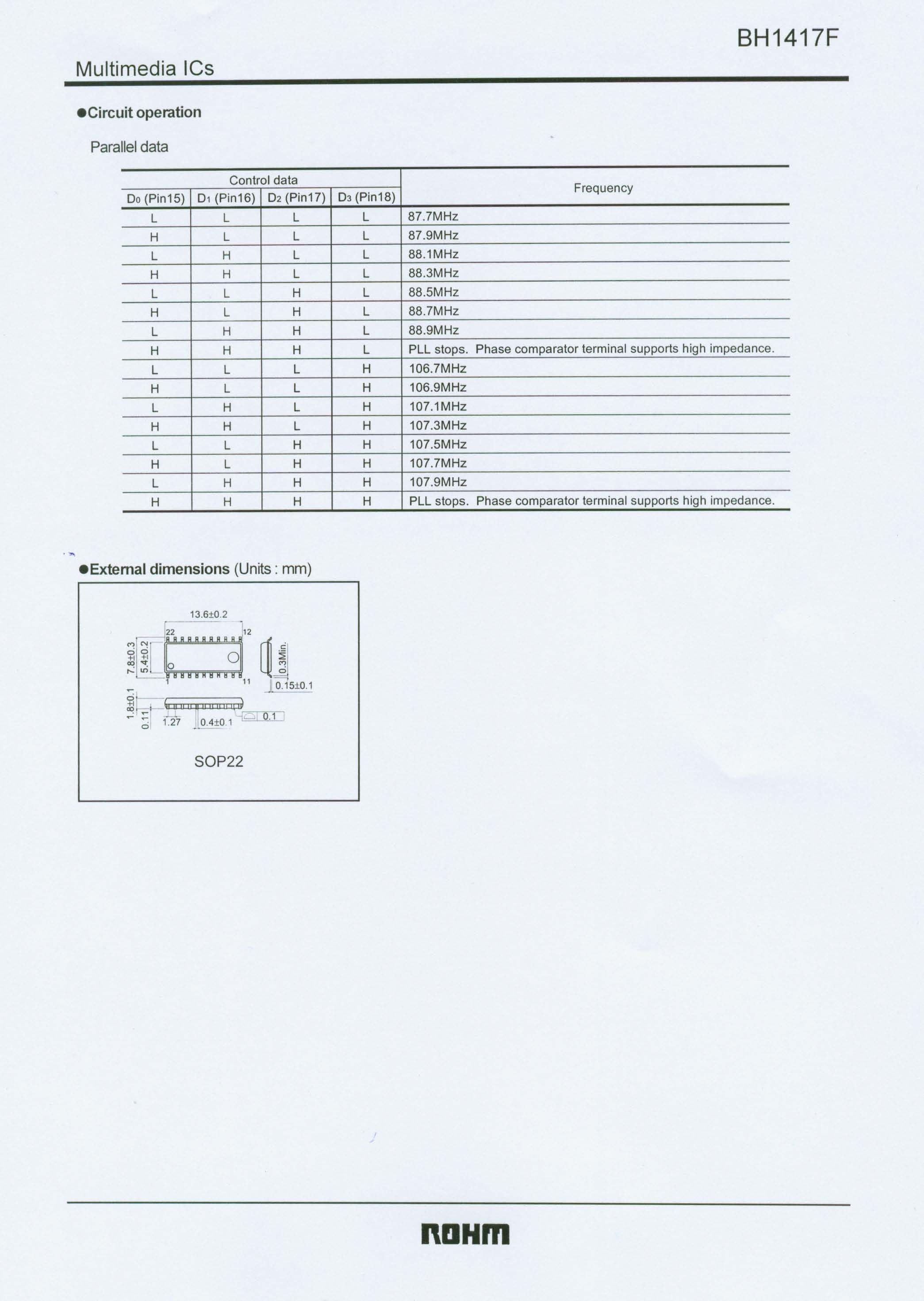
7/April/2006 FCC information CCB110 Circuitry amend as following: 1/ BH1417 transmitter IC pin 16, pin 17, pin 18, when code switch turn to 87.7Mhz and 87.9Mhz position, code switch to control this IC pin 16, pin 17, pin 18 all to level low. Please see attached IC BH1417 diagram. 2/ Added IC6 CD4025 NOR Gate and Q15 S8550 PNP transistor to control transmitter IC3 operation voltage on/off, CD4025 input pin 11, pin 12, pin 13 from code switch with encode signal when all signal is low level enable the CD4025 output pin to control Q15 S8550 PNP transistor disable, then IC3 BH1417 without power can’t operate. 3/ Attached IC 4025 pdf file for reference. 4/ Attached circuit diagram amend with IC6 CD4025 and Q15 S8550 transistor for transmit frequency 87.7Mhz and 87.9Mhz function disable. Best Regards Y.M. Lai (project engineer) 7/April/2006 Unigold Industrial Company
Operational Description
DATA SHEET Product specification File under Integrated Circuits, IC04 January 1995 INTEGRATED CIRCUITS HEF4025B gates Triple 3-input NOR gate For a complete data sheet, please also download: •The IC04 LOCMOS HE4000B Logic Family Specifications HEF, HEC •The IC04 LOCMOS HE4000B Logic Package Outlines/Information HEF, HEC January 19952 Philips SemiconductorsProduct specification Triple 3-input NOR gate HEF4025B gates DESCRIPTION The HEF4025B provides the positive triple 3-input NOR function. The outputs are fully buffered for highest noise immunity and pattern insensitivity of output impedance. Fig.1 Functional diagram. FAMILY DATA, I DD LIMITS category GATES See Family Specifications HEF4025BP(N):14-lead DIL; plastic (SOT27-1) HEF4025BD(F):14-lead DIL; ceramic (cerdip) (SOT73) HEF4025BT(D):14-lead SO; plastic (SOT108-1) ( ): Package Designator North America Fig.2 Pinning diagram. Fig.3 Logic diagram (one gate). January 19953 Philips SemiconductorsProduct specification Triple 3-input NOR gate HEF4025B gates AC CHARACTERISTICS V SS = 0 V; T amb =25°C; C L = 50 pF; input transition times≤20 ns V DD V SYMBOLTYP.MAX. TYPICAL EXTRAPOLATION FORMULA Propagation delays I n →O n 570135ns43 ns+(0,55 ns/pF) C L HIGH to LOW10t PHL 2555ns14 ns+(0,23 ns/pF) C L 152040ns12 ns+(0,16 ns/pF) C L 560120ns33 ns+(0,55 ns/pF) C L LOW to HIGH10t PLH 2550ns14 ns+(0,23 ns/pF) C L 151535ns7 ns+(0,16 ns/pF) C L Output transition times560120ns10 ns+(1,0 ns/pF) C L HIGH to LOW10t THL 3060ns9 ns+(0,42 ns/pF) C L 152040ns6 ns+(0,28 ns/pF) C L 560120ns10 ns+(1,0 ns/pF) C L LOW to HIGH10t TLH 3060ns9 ns+(0,42 ns/pF) C L 152040ns6 ns+(0,28 ns/pF) C L V DD V TYPICAL FORMULA FOR P (μW) Dynamic power5900 f i +∑(f o C L )×V DD 2 where dissipation per104000 f i +∑(f o C L )×V DD 2 f i = input freq. (MHz) package (P)1510 900 f i +∑(f o C L )×V DD 2 f o = output freq. (MHz) C L = load capacitance (pF) ∑(f o C L ) = sum of outputs V DD = supply voltage (V)
Operational Description
1. Our product can receive normal FM broadcast signal. The normal broadcasting station can not only be allowed to broadcast normal phonetic and musical voices, but the negative carrier named as SCA (Subsidiary Communications Authorization) contained in the broadcast signal is also permitted by FCC. The function of our product is that it can convert the SCA signal to normal FM signal and then send it out. Thus it can make ordinary FM car radio receive this signal. 2. If our product cannot receive SCA broadcast signal, the transmitter will stop transmitting.
Operational Description
10/May/2006 Dear Ms Helen Please transfer comment and circuitry to ATCB investigation For our model CCB110 already modify to broadcast station no audio signal (without modulation time) stop transmitter operation. receiver reception carrier signal when unit detect without audio signal time, IC4 MC3361 pin 13 output one distinguish signal via IC6 CD4025 and Q16 8550 transistor to disable transmitter IC power source. Best Regards Y.M. Lai (project engineer) 10/May/2006 Email : [email protected]
Operational Description
Instruction Sheet Model CCB110 operation procedure: 1/ Connect power cord (attach parts) DC plug end to converter unit right side DC jack 2/ Connect power cord cigarette smoke plug end to car meter panel smoke lighter socket. 3/ Extent converter unit rear side rod antenna to maximum length and bend to vertical direction. 4/ Tune transmitter rotary knob (converter unit rear side) to 88.1Mhz (converter unit on top with lens window) 5/ Press on/off power switch once (Converter unit on top of front side) left side LED light off 6/ Press on/off power switch again, left side LED light on. 7/ Power on car radio and tune to 88.1Mhz position, you will listen SCA signal from car radio speaker. 8/ Note if 88.1Mhz already with broadcasting station, please change item 4 frequency choose empty broadcast station place 9/ Converter unit transmitter with 12 channel : 88.1 88.3 88.5 88.7 88.9 and 106.7 106.9 107.1 107.3 107.5 107.7 107.9MHz 12 channel 10/ Front panel right side with Filter switch, press once filter function off, sound high tone little bit increase, press again filter function on, sound high tone little bit decrease. 11/ Unit build in transmitter transmit signal to car antenna (distance with in 5 meter)
Test Report
FCC ID: T4ICCB110 Report No.: 060313FIA01 1 Issued: Mar. 30, 2006 FCC TEST REPORT REPORT NO.: 060313FIA01 MODEL NO.: CCB110 RECEIVED: Mar. 8, 2006 TESTED: Mar. 8 ~ Mar. 29, 2006 ISSUED: Mar. 30, 2006 APPLICANT: UNIGOLD INDUSTRIAL COMPANY ADDRESS: FLAT A 2/F, EPOCH IND., BLDG., 8 CHEUNG HO STREET, TSING YT, N.T.HK ISSUED BY: ADT (Shanghai) Corporation ADDRESS: 2F, Building C, No.1618, Yishan Rd., 201103, Shanghai, China This test report consists of 25 pages in total. It may be duplicated completely for legal use with the approval of the applicant. It should not be reproduced except in full, without the written approval of our laboratory. The client should not use it to claim product endorsement by A2LA or any government agencies. The test results in the report only apply to the tested sample. ADT (Shanghai) Corporation FCC ID: T4ICCB110 Report No.: 060313FIA01 2 Report Format Version 1.0.0 TABLE OF CONTENTS 1 CERTIFICATION..............................................................................................3 2 SUMMARY OF TEST RESULTS .....................................................................4 2.1 MEASUREMENT UNCERTAINTY...................................................................5 3 GENERAL INFORMATION ..............................................................................6 3.1 GENERAL DESCRIPTION OF EUT ................................................................6 3.2 DESCRIPTION OF TEST MODES ..................................................................6 3.3 GENERAL DESCRIPTION OF APPLIED STANDARDS..................................7 3.4 DESCRIPTION OF SUPPORT UNITS ............................................................7 3.5 CONFIGURATION OF SYSTEM UNDER TEST.............................................7 4 TEST TYPES AND RESULTS .........................................................................8 4.1. CONDUCTED EMISSION MEASUREMENT...................................................8 4.1.1. LIMITS OF CONDUCTED EMISSION MEASUREMENT ................................8 4.1.2. TEST RESULTS ..............................................................................................8 4.2 RADIATED EMISSION MEASUREMENT........................................................9 4.2.1 LIMITS OF RADIATED EMISSION MEASUREMENT .....................................9 4.2.2 TEST INSTRUMENT .....................................................................................10 4.2.3 TEST PROCEDURE...................................................................................... 11 4.2.4 DEVIATION FROM TEST STANDARD.......................................................... 11 4.2.5 TEST SETUP.................................................................................................12 4.2.6 EUT OPERATING CONDITION.....................................................................12 4.2.7 TEST RESULT...............................................................................................13 4.3 EMISSION BAND MEASUREMENT .............................................................19 4.3.1 LIMITS OF EMISSION BAND MEASUREMENT...........................................19 4.3.2 TEST INSTRUMENTS...................................................................................19 4.3.3 TEST PROCEDURE......................................................................................19 4.3.4 DEVIATION FROM TEST STANDARD..........................................................20 4.3.5 TEST SETUP.................................................................................................20 4.3.6 EUT OPERATING CONDITIONS ..................................................................20 4.3.7 TEST RESULTS ............................................................................................21 5 APPENDIX - INFORMATION ON THE TESTING LABORATORIES ........... A-1 FCC ID: T4ICCB110 Report No.: 060313FIA01 3 Report Format Version 1.0.0 1 CERTIFICATION PRODUCT: SCA CAR CONVERTER MODEL NO.: CCB110 APPLICANT: UNIGOLD INDUSTRIAL COMPANY TESTED: Mar. 8 ~ Mar. 29, 2006 TEST ITEM: Engineering Sample STANDARDS: FCC Part 15, Subpart C (Section 15.237), ANSI C63.4-2003 We, ADT (Shanghai) Corporation, declare that the equipment above has been tested in our facility and found compliance with the requirement limits of applicable standards. The test record, data evaluation and Equipment Under Test (EUT) configurations represented herein are true and accurate under the standards herein specified. TECHNICAL ACCEPTANCE : , DATE:MAR. 30, 2006 Responsible for EMI Steven Qian Engineering Supervisor APPROVED BY : , DATE:MAR. 30, 2006 Director of Operations Wallace Pan Director of Operations FCC ID: T4ICCB110 Report No.: 060313FIA01 4 Report Format Version 1.0.0 2 SUMMARY OF TEST RESULTS The EUT has been tested according to the following specifications: APPLIED STANDARD: FCC Part 15, Subpart C STANDARD PARAGRAPH TEST TYPE RESULTREMARK 15.207 Conducted Emission TestN/A Refer to 4.1.2 Radiated Emission Test (Mode 1, Previous data) PASS Minimum passing margin is –15.22dB at 265.230 MHz Radiated Emission Test (Mode 1, Debugging data) PASS Minimum passing margin is –16.42dB at 265.230 MHz Radiated Emission Test (Mode 2, Previous data) PASS Minimum passing margin is –1.46dB at 213.390 MHz Radiated Emission Test (Mode 2, Debugging data) PASS Minimum passing margin is –2.47dB at 213.580 MHz Radiated Emission Test (Mode 3, Previous data) PASS Minimum passing margin is –0.37dB at 215.840 MHz 15.239 Radiated Emission Test (Mode 3, Debugging data) PASS Minimum passing margin is –1.34dB at 215.340 MHz 15.239(c) Emission Bandwidth TestPASS Meet the requirements NOTE: The information of measurement uncertainty is available upon the customer’s request. FCC ID: T4ICCB110 Report No.: 060313FIA01 5 Report Format Version 1.0.0 2.1 MEASUREMENT UNCERTAINTY Where relevant, the following measurement uncertainty levels have been estimated for tests performed on the EUT as specified in CI…
Text truncated - open the document above for the full version.
Contact Information
Applicant
LAI Y.M.
Technical Contact
ADT (Shanghai) CorporationWallace Pan
[email protected]86-21-6465-9091
2F, Building C, No. 1618, Yishan rd., · Shanghai · China
Non-Technical Contact
ADT (Shanghai) CorporationLily Liu
[email protected]86-21-6465-9091
Test Firm
BUREAU VERITAS ADT (Shanghai) CorporationZhaoqian YU
Technical Specifications
| # | Rule Parts | Frequency Range | Power Output |
|---|---|---|---|
| 2 | 15C | 106.7 MHz - 107.9 MHz | - |