T4ZZYZM001CFL
Exald Corporation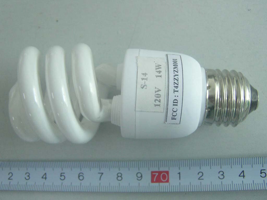
Click to zoom
Application Details
- Equipment Class
- 8CC - Part 18 Consumer Device
- Date of Grant
- Jul 05, 2006
- Application Purpose
- Original Equipment
- Date of Application
- Jul 05, 2006
- Equipment Note
- CFL
- Frequency Range
- 0.06200000 - 0.06300000
- Company
- Exald Corporation
- Country
- United States
Documents & Files
Document Text
Text extracted from the exhibit documents filed with the FCC. Open a document above to read the original.
Users Manual
Energy Saving Lamp Introduction · Conserves natural resources by at least saving 80% electricity than incandescent bulbs. · About 6 times lamp life than a standard incandescent bulb. Notice For Use ·Never use with the following fixtures: dimming circuit emergency lighting fixtures electronic timer fixtures direct current fixtures ·Use only at the rated voltage and frequency circuit. The power voltage must be in the range of 120V±10%. ·Use indoor only. Never use it where water may drop on the lamp or where the atmosphere is humid. ·Do not use in enclosed fixture,Or the lamp’s life would be shorten. ·Always turn off the switch when replacing or cleaning the lamp. Remove and install it by grasping only the plastic portion of the lamp. ·Added weight may cause instability of free-standing portable lamps in which the distancefrom the bottom of the base to top of the lamp hold dose not exceed 3 times minimum vase width. Use only with portable lamps which are provided with lamp shade. The lamps are designed to start at very low supply voltages down to about 108VAC and even lower if required, they are also designed to tolerate short term very high supply voltage surges up to 132VAC. These features are most important for developing area where the supply voltage can fluctuate widely. They have short circuit protection ,all plastic materials used are certified Fire Retardant, they can be safely operated in the temperature range of -20°C to +65°C ·This product complies with Part 18 of the FCC Rules but may cause interference to radios, television , wireless telephones, and remote controls. If interference occurs, move product away from the device or plug either into a different outlet. This product may cause unterference to radio equipment and should not be installed near maritime safety communications equipment or other critical navigation or communication equipment operating between 0.45-30 MHz.
External Photos
External Photos G-9W: EUT View 1 G-9W: EUT View 2 S-14W: EUT View 1 S-14W: EUT View 2
ID Label/Location Info
ID Label Label FCC ID: T4ZZYZM001
ID Label/Location Info
ID Label/Location Label Location Information Specifications: Text is Black or white in color and is left justified. Labels are printed in indelible ink on permanent adhesive backing or silk-screened onto the EUT or shall be affixed at a conspicuous location on the EUT. Refer to the below arrow. G-9W S-14W
Internal Photos
Internal Photos G-9W: EUT- Inside View G-9W: EUT–PCB View (1) G-9W: EUT–PCB View (2) S-14W: EUT–Inside View S-14W: EUT–PCB View (1) S-14W: EUT–PCB View (2)
Parts List/Tune Up Info
G-9S-14 BILL OF MATERIAL Kind of component Manufacturer Information about type, current,power, transformer specitication number, nsulating class Test mark form(VDE,BSI,ULetc.) 1. Fuse 2. heat-shrinkable tube 3. Diode(D1-D5) 4. electroniclytic capacitor(C5) 5. transistor 6. lamp choke(L) 7. capacitor(C4) 8. capacitor(C5) 9. Internal wire 10. Plastic for enclosure Walter Electronic Co.,Ltd Shanghai Changbao Special Plastic Products CO.,LTD Yangzhou Yangjie Electronic Corp. Zhaoqing Hongyi Electronics CO., LTD 1. Jilin Sino Microclcotronics CO.,LTD 2.Yangzhou Jinshi High Technology CO.,LTD Yangzhou Yongxing Electronics CO.,LTD Zhejiang changxing Capacitor Zhejiang changxing Capacitor Yuyao Lianghui Nanmiao Electric Wire Factory 1.Changzhou Wujin Boyi Plastic Products Factory 2.Changzhou Luyang Yanghu Products Factory ICP AC 125V,1A DRS 600V,125,VW-1 1N4007 1000V,1A 10F 200V 105 9W:13002-92/DK42/4124 14W:13002-126/DK42/D4124 9WE13 1.3mH, 135 14WE13 1.0mH,135 CL21 400V 100nJ 9WCH11 1000V 2n7 14WCH11 1000V 4n7 ZR-RV 0.3mm 2 201T UL,CSA CSA,ULE203831 No No No No No No No E231643 UL E152735
Schematics
Model: G-9, S-14 Q1Q2 D1~D4 C0 C2 C3 C4 C5 C6 D5 D7D8 F L0 L BB B C1 D6 R1R2 R6R5 120v
Test Report
Note: The test report is specially limited to the above company and this particular sample only. It may not be duplicated without prior written consent of Bay Area Compliance Lab Corp. (ShenZhen). This report must not be used by the client to claim product certification, approval, or endorsement by NVLAP, NIST or any agency of the US Government. FCC PART 18 EMI MEASUREMENT AND TEST REPORT For Exald Corporation 166 California Street, unit C Arcadia, CA 91006. USA FCC ID:T4ZZYZM001 June 22, 2006 This Report Concerns: Original Report Equipment Type: CFL Test Engineer: William Chan Report Number: RSH06021581 Test Date: March 21, 2006 Reviewed By: Boni Baniqued Prepared By: Bay Area Compliance Lab Corp. (ShenZhen) 6/F, the 3rd Phase of WanLi Industrial Building, ShiHua Road, FuTian Free Trade Zone, ShenZhen, GuangDong 518038, P.R.China Tel: +86-755-33320018 Fax: +86-755-33320008 Exald Corporation FCC ID: T4ZZYZM001 Report # RSH06021581 Page 2 of 12 FCC Part 18 Report TABLE OF CONTENTS GENERAL INFORMATION.......................................................................................................................................3 PRODUCT DESCRIPTION FOR EQUIPMENT UNDER TEST (EUT) .....................................................................................3 OBJECTIVE...................................................................................................................................................................3 RELATED SUBMITTAL(S)/GRANT(S).............................................................................................................................3 TEST METHODOLOGY..................................................................................................................................................3 TEST FACILITY.............................................................................................................................................................3 EXTERNAL I/O CABLE..................................................................................................................................................4 SYSTEM TEST CONFIGURATION ..........................................................................................................................5 JUSTIFICATION.............................................................................................................................................................5 EQUIPMENT MODIFICATIONS.......................................................................................................................................5 CONFIGURATION OF TEST SETUP.................................................................................................................................5 BLOCK DIAGRAM OF TEST SETUP................................................................................................................................5 CONDUCTED EMISSION...........................................................................................................................................6 MEASUREMENT UNCERTAINTY....................................................................................................................................6 EUT SETUP..................................................................................................................................................................6 EMI TEST RECEIVER SETUP.........................................................................................................................................7 TEST EQUIPMENT LIST AND DETAILS...........................................................................................................................7 TEST PROCEDURE........................................................................................................................................................7 TEST RESULTS SUMMARY............................................................................................................................................7 TEST DATA..................................................................................................................................................................7 PLOT(S) OF TEST DATA................................................................................................................................................8 Exald Corporation FCC ID: T4ZZYZM001 Report # RSH06021581 Page 3 of 12 FCC Part 18 Report GENERAL INFORMATION Product Description for Equipment under Test (EUT) The Exald Corporation’s model: G-9 , S-14, or the “EUT” as referred to in this report is a CFL which measures approximately G-9W: 12.0 cm L x 6.5 cm W, S-14W: 10.5 cm L x 4.5cmW, rated input voltage: AC 120V/60Hz. * The test data gathered are from production sample, serial number: 0602204. Provided by the manufacturer, we received EUT on 2006-2-15. Objective The following test report is prepared on behalf of Exald Corporation in accordance with Part 2, Subpart J, and Part 18, Subparts A, B and C of the Federal Communication Commissions rules and regulations. The objective of the manufacturer is to determine compliance with FCC Part 18 limits. Related Submittal(s)/Grant(s) No related submittal(s). Test Methodology All measurements contained in this report were conducted with MP-5, FCC Methods of Measurements of Radio Noise Emissions from ISM Equipment, February 1986. All measurement was performed at Bay Area Compliance Lab Corp. (ShenZhen). The radiated testing was performed at an antenna-to-EUT distance of 3 meters. Test Facility The Test site used by Bay Area Compliance Lab Corp. (ShenZhen) to collect radiated and conducted emission measurement data is located in the 6/F, the 3rd Phase of WanLi Industrial Building, ShiHua Road, FuTian Free Trade Zone, ShenZhen, GuangDong 518038, P.R.China. Test site at Bay Area Compliance Lab Corp. (ShenZhen) has been fully described in reports submitted to the Federal Communication Comm…
Text truncated - open the document above for the full version.
Test Setup Photos
Test Setup Photos G-9W: Conducted Emission - Front View G-9W: Conducted Emission - Rear View S-14W: Conducted Emission - Front View S-14W: Conducted Emission - Rear View
Contact Information
Applicant
Michael Solichin
Test Firm
Bay Area Compliance Laboratory Corp. (Shenzhen)John Chan
Technical Specifications
| # | Rule Parts | Frequency Range | Power Output |
|---|---|---|---|
| 1 | 18 | 0.062 MHz - 0.063 MHz | - |
Other Applications from Exald Corporation
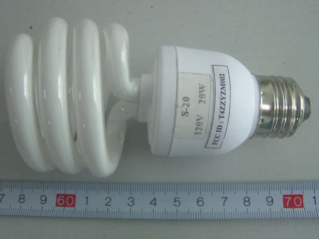
T4ZZYZM002
Jul 05, 2006CFL
Equipment Class
8CC - Part 18 Consumer Device