T59-AMP10RTire Pressure Monitoring System
ABEX Manufacturing SDN. BHD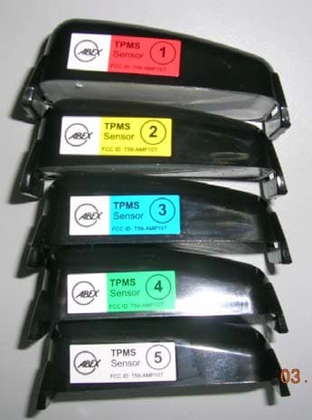
Click to zoom
Application Details
- Equipment Class
- CYY - Communications Receiver used w/Pt 15 Transmitter
- Date of Grant
- Jun 05, 2006
- Application Purpose
- Original Equipment
- Date of Application
- Jun 05, 2006
- Equipment Note
- Tire Pressure Monitoring System
- Frequency Range
- 433.92000000 - 433.92000000
- Company
- ABEX Manufacturing SDN. BHD
- Country
- Malaysia
Documents & Files
Document Text
Text extracted from the exhibit documents filed with the FCC. Open a document above to read the original.
Users Manual
Tire Pressure Monitoring System AMP-10s / AMP-10f USER’S GUIDE. Manufacturing Fitting and commissioning to be carried out by qualified personnel only in accordance with the operating instructions. DISCLAIMER THE MATERIALS ARE PROVIDED "AS IS" WITHOUT ANY EXPRESS OR IMPLIED WARRANTY OF ANY KIND INCLUDING WARRANTIES OF MERCHANTABILITY, NONINFRINGEMENT OF INTELLECTUAL PROPERTY, OR FITNESS FOR ANY PARTICULAR PURPOSE. IN NO EVENT SHALL ABEX OR ITS SUPPLIERS BE LIABLE FOR ANY DAMAGES WHATSOEVER (INCLUDING, WITHOUT LIMITATION, DAMAGES FOR LOSS OF PROFITS, BUSINESS INTERRUPTION, LOSS OF INFORMATION) ARISING OUT OF THE USE OF OR INABILITY TO USE THE MATERIALS, EVEN IF ABEX HAS BEEN ADVISED OF THE POSSIBILITY OF SUCH DAMAGES. BECAUSE SOME JURISDICTIONS PROHIBIT THE EXCLUSION OR LIMITATION OF LIABILITY FOR CONSEQUENTIAL OR INCIDENTAL DAMAGES, THE ABOVE LIMITATION MAY NOT APPLY TO YOU. ABEX Manufacturing and its suppliers further do not warrant the misuse, abuse or improper installation or operation of Tire Pressure Monitoring system or the failure of a user to promptly and appropriately respond to an alert by this system. ABEX Manufacturing may make changes to these materials, or to the products described therein, at any time without notice. ABEX Manufacturing makes no commitment to update the Materials. Warning, Caution Pages Content 1 Notices • Product usage • Reacting to alerts • Use of chemical • Periodical maintenance • Regulations 2 Product overview • Definition........................................................................ • Factory setting • Pressure alert................................................................... • Temperature alert • Packing list Operating parts and connection • Display unit • Receiver unit • Sensor unit 5 Symbol on the display 6 Installation of sensor / transmitter unit 7 De-Installation of sensor / transmitter unit 8 Installation of display unit 9 Operation 10 Setting mode • Entering main menu.......................................................... • Returned to monitoring mode • Pressure and temperature unit selection ................................... • Pressure and temperature threshold setting ................................ • Tire rotation ................................................................... • Sensor programming ......................................................... Other setting • Spare tire activation • ON-OFF display 16 Eliminating faults 17 Technical specification 18 1 CONTENTS 3 4 12 13 14 15 11 Product usage • ABEX Tire Pressure Monitoring System is a safety device that measure and display tires pressure and temperature. The system will alert drivers by visual and audio, when irrelevant of pressure and temperature are detected. • The device is suitable for use in passenger cars, 4WD and light trucks that use maximum tire pressure up to 78Psi (or 538Kpa). Reacting to alerts • When an alert is appear, reduce vehicle speed gradually and proceed to a safe stopping location for necessary inspection. • Low pressure alert indicate tire pressure has dropped to pre-determine setting value. Inflation is necessary. • Rapid deflation alert is normally activated when puncture or pressure reduce beyond safety setting value, that requires for further action. • High temperature alert could happen due to severe abrasion due to braking, vehicle overloaded or massive heat transfer by other parts of vehicles that need to be rectified accordingly. • It is the Users responsibility to react promptly and appropriately during the alerts. Use of Chemicals • Temporary resealing and re-inflation products that contains sealant or propellant chemicals inside tires may adversely affect the functionality of the sensors unit. Periodical Maintenance • Confirm the sensor is functioning for all tires by monitoring the pressure and temperature updates in the display. REGULATIONS UNITED STATES FEDERAL COMMUNICATIONS COMMISSION (FCC) This device complies with Part 15 of the FCC Rules. Operation is subject to the following two conditions: (1) this device may not cause harmful interference, and (2) this device must accept any interference received, including interference that may cause undesired operation. This equipment has been tested and found to comply with the limits for a Class B digital device, pursuant to Part 15 of the FCC Rules. These limits are designed to provide reasonable protection against harmful interference in a residential installation. This equipment generates uses and can radiate radio frequency energy and, if not installed and used in accordance with the instructions, may cause harmful interference to radio communications. However, there is no guarantee that interference will not occur in a particular installation. If this equipment does cause harmful interference to radio or television reception, which can be determined by turning the equipment off and on, the user is encouraged to try to correct the interference by one or more of the following measures: • Reorient or relocate the receiving antenna. • Increase the separation between the equipment and receiver. • Connect the equipment into an outlet on a circuit different from that to which the receiver is connected. Caution: Any changes or modifications in construction of this device which are not expressly approved by the party responsible for compliance could void the user’s authority to operate the equipment. 2 NOTICES It is important to check your vehicle's tire pressure at least once a month for the following reasons: Â Most tires may naturally lose air over time. Â Tires can lose air suddenly if you drive over a pothole or other object or if you strike the curb when parking. Â With radial tires, it is usually not possible to determine under inflation by visual inspection. For convenience, purchase ABEX tire pressure monitoring system to keep in your vehicle. Properly maintained tires improve the steering, stopping, traction, and load-carrying capability of your vehicle. Under inflat…
Text truncated - open the document above for the full version.
External Photos
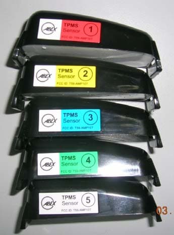
ABEX MANUFACTURING SDN. BHD. (Company No. 620802-M) Lot 2-6, Jalan SU/6A, Lion Industrial Park, Section 26, 40400 Shah Alam, Selangor Darul Ehsan, Malaysia Tel: (03) 5192 2898 Fax: (03) 5192 2633 2. Labels position. 2. 1. Remark Unit No Receiver Sensor Label sensor ID quantity may varies base on model part no. AMP-10s = 4 sensor Label sensor ID = 4pcs AMP-10f = 5 sensor Label sensor ID = 5pcs FCC ID: T59-AMP10T Note: 1) Label sensor ID number must be corresponding to ID assign number in display unit. Photo Label Specification Label sensor ID FCC ID: T59-AMP10R ABEX MANUFACTURING SDN. BHD. (Company No. 620802-M) Lot 2-6, Jalan SU/6A, Lion Industrial Park, Section 26, 40400 Shah Alam, Selangor Darul Ehsan, Malaysia Tel: (03) 5192 2898 Fax: (03) 5192 2633 3. EUT external photo. 2. 1. Remark Unit No Receiver Sensor Photo Side viewTop view Bottom view Top view Side view
Internal Photos
ABEX MANUFACTURING SDN. BHD. (Company No. 620802-M) Lot 2-6, Jalan SU/6A, Lion Industrial Park, Section 26, 40400 Shah Alam, Selangor Darul Ehsan, Malaysia Tel: (03) 5192 2898 Fax: (03) 5192 2633 4. EUT internal photo. 2. 1. Remark Unit No Receiver Sensor Photo Top view Bottom view Top view Bottom view
Test Report
KTL Korea Testing Laboratory Page 1 of 8 TEST REPORT This test report only responds to the tested sample and shall not be reproduced except in full without written approval of the Korea Testing Laboratory. Tested and reported by Reviewed by Sung-Kyu Cho, Engineer Seok-Jin Kim , Telecommunication Team Manager KOREA TESTING LABORATORY FG101-01-02-00 222-13, Guro-Dong Guro-Gu Seoul Korea 152-053 http://www.ktl.re.kr Ref. Report No. 06-1341-010-02 Name and address of the applicant ABEX MANUFACTURING SDN BHD Lot 2-6, Jalan SU/6A, Lion Industrial Park, Section 26, 40400 Shah Alam, Selangor Darul Ehsan, Malaysia Standard / Test regulation FCC Part 15, Subpart B Test result Pass Incoming date : May 22, 2006 Test item(s) ; Communication Receiver used wih Part 15 Tx (Tire Pressure Monitoring System) Model/type ref. ; AMP-10s / AMP-10f Manufacturer ; ABEX MANUFACTURING SDN BHD Additional information ; -Required Authorization : Certification -FCC ID. : T59-AMP10R -Note : Test report(Certification) of Transmitter portion of this System is issued on Ref. Report No.06-1341-010-01 Test date : May 22, 2006 Issue date : May 24, 2006 Ref. Report No. 06 – 1341 – 010 – 02 Page 2 of 8 Korea Testing Laboratory Telecommunication Team 222-13, Guro3-dong, Guro-gu, Seoul Korea 152-848 TABLE OF CONTENTS I. GENERAL INFORMATION 3 1. Grantee’s Name and Mailing Address 2. Manufacturer's Name and Mailing Address 3. Equipment Descriptions 4. Rules and Regulations 5. Measuring Procedure 6. Place of Measurement 7. Date of Measurement II. GENERAL REQUIREMENTS OF THE EUT 4 1. Labeling Requirement (Section 15.19) 2. Information to User (Sections 15.21) 3. Special Accessories (Section 15.27) III. RADIATED EMISSION MEASUREMENT (Section 15.109) 5 1. Test Procedure 2. Photograph for the test configuration 3. Sample Calculation 4. Measurement Data IV. TEST EQUIPMENTS USED FOR MEASUREMENT 8 Ref. Report No. 06 – 1341 – 010 – 02 Page 3 of 8 Korea Testing Laboratory Telecommunication Team 222-13, Guro3-dong, Guro-gu, Seoul Korea 152-848 I. GENERAL INFORMATION 1. Grantee’s Name and : ABEX MANUFACTURING SDN BHD Mailing Address Lot 2-6, Jalan SU/6A, Lion Industrial Park, Section 26, 40400 Shah Alam, Selangor Darul Ehsan, Malaysia 2. Manufacturer's Name and : ABEX MANUFACTURING SDN BHD Mailing Address Lot 2-6, Jalan SU/6A, Lion Industrial Park, Section 26, 40400 Shah Alam, Selangor Darul Ehsan, Malaysia 3. Equipment Descriptions 3.1 Operating Frequency : 433.92 MHz 3.2 Detect Method : Superheterodyne Detector 3.3 Power Supply : DC 12V(Car Battery) 4. Rules and Regulations : FCC Part 15, Subpart B 5. Measuring Procedure : ANSI C63.4-2003 6. Place of Measurement : Absorber-lined Room (KTL) 7. Date of Measurement 7.1 Conducted Emission : Not Applicable 7.2 Radiated Emission : May 22, 2006 Ref. Report No. 06 – 1341 – 010 – 02 Page 4 of 8 Korea Testing Laboratory Telecommunication Team 222-13, Guro3-dong, Guro-gu, Seoul Korea 152-848 II. GENERAL REQUIREMENTS OF THE EUT 1. Labeling Requirement (Section 15.19) This device complies with Part 15 of the FCC Rules. Operation is subject to the following two conditions: (1) this device may not cause harmful interface, and (2) this device must accept any interference received, including interference that may cause undesired operation. 1.1 Location of Label : User’s Guide Manual 1.2 How Applied : Printed 2. Information to User (Section 15.21) The following or similar statements were provided in the manual for user instruction. Please refer page 4 of the attached manual for details. CAUTION : Any changes or modifications in construction of this device which are not expressly approved by the party responsible for compliance could void the user's authority to operate the equipment. 3. Special Accessories (Section 15.27) 3.1 Were the special Accessories provided? [ ] yes, [ x ] no 3.2 If yes, details for the special accessories are as follows : 3.3 If yes, were the appropriate instructions provided on the first page of the text concerned with the installation of the device? [ ] yes, [ ] no 3.4 Are these accessories provided of the type which can be readily obtained from multiple retail outlets ? [ ] yes, [ ] no And therefore does the manual specify what additional components or accessories are required to used in order to comply with the Rules? [ ] yes, [ ] no Ref. Report No. 06 – 1341 – 010 – 02 Page 5 of 8 Korea Testing Laboratory Telecommunication Team 222-13, Guro3-dong, Guro-gu, Seoul Korea 152-848 III. RADIATED EMISSION MEASUREMENT (Section 15.109) 1. Test Procedure 1.1 Preliminary Testing for Reference Preliminary testing was performed in a KTL absorber-lined room to determine the emission characteristics of the EUT. The EUT was placed on the wooden table which has dimensions of 0.8 meters in height, 1 meter in length and 1.5 meters in width. Receiving antenna (Biconi-Log antenna : 30 to 1000 MHz or Horn Antenna : 1 to 18 GHz) was placed at the distance of 1 meter from the EUT. An attempt was made to maximize the emission level with the various configurations of the EUT. Emission levels from the EUT with various configurations were examined on a spectrum analyzer connected with a RF amplifier and graphed by a plotter. 1.2 Final Radiated Emission Test at an Absorber-Lined Room The final measurement of radiated field strength was carried out in a KTL absorber-lined Room that was listed up at FCC according to the "Radiated Emissions Testing" procedure specified by ANSI C63.4. Based on the test results in preliminary test, measurement was made in same test set up and configuration with 3 orthogonal planes which produced maximum emission level. Receiving antenna was installed at 3-meter distance from the EUT, and was connected to an EMI receiver or spectrum analyzer with a RF amplifier. Turntable was rotated through 360 degrees and receiving antenna height was varied from 1 to 4 meters above the ground plane with horizontal and vertical polarization to read maximum emission level. If necessary, the radiat…
Text truncated - open the document above for the full version.
Contact Information
Applicant
Somu Dayaananthan(Project Executive)
Test Firm
Korea Testing LaboratoryJeong-Min Kim
Technical Specifications
| # | Rule Parts | Frequency Range | Power Output |
|---|---|---|---|
| 1 | 15B | 433.92 MHz - 433.92 MHz | - |
Other Applications from ABEX Manufacturing SDN. BHD
T59-AMP10T
Jun 05, 2006Tire Pressure Monitoring System
Equipment Class
DSC - Part 15 Security/Remote Control Transmitter