T5K96601R/C Model
Great Mountain Electric Technology Company Limited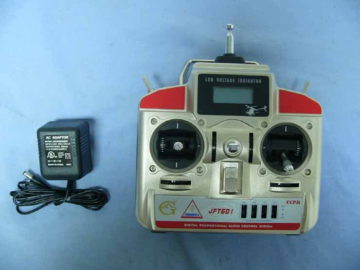
Click to zoom
Application Details
- Equipment Class
- TNB - Licensed Non-Broadcast Station Transmitter
- Date of Grant
- May 22, 2006
- Application Purpose
- Original Equipment
- Date of Application
- May 22, 2006
- Equipment Note
- R/C Model
- Frequency Range
- 72.85000000 - 72.85000000
- Country
- China
Documents & Files
Document Text
Text extracted from the exhibit documents filed with the FCC. Open a document above to read the original.
Users Manual
When the throttle stick is pushed up , the electric motor and pitch ( main rotor ) increase . As a result , helicopter lifts up . AILERON OPERATION When the aileron stick is moved to the right , the swashplate should also tilt to the right , the helicopter moves to the right . When the aileron stick is moved to the left , the swashplate should also tilt to the left , the helicopter moves to the left . When the throttle stick is pulled back , the electric motor and pitch ( main rotor ) decrease . As a result , helicopter decreases . THROTTLE OPERATION Moving Left ON SERVO REVERSER AIL ELE THR RUD REV NOR JFT601 CCPM R NL CHAN E S 6 DI GITA L PRO PO RT ION AL RA DI O CON TRO L SYS TEM LCD VOLTAGE INDICATOR Moving Right ON SERVO REVERSER AIL ELE THR RUD REV NOR JFT601 CCPM R NL CHAN E S 6 DI GITA L PRO PO RTI ONA L RA DI O CON TRO L SYS TE M LCD VOLTAGE INDICATOR Upward ( Mode2 )( Mode1 ) ON SERVO REVERSER AIL ELE THR RUD REV NOR JFT601 CCPM R N L CHAN E S 6 DI GI TAL PRO PO RT ION AL RA DI O CON TRO L SYS TE M LCD VOLTAGE INDICATOR Downward ( Mode2 )( Mode1 ) ON SERVO REVERSER AIL ELE THR RUD REV NOR JFT601 CCPM R CHAN NE LS 6 DI GI TAL PRO PO RTI ONA L RA DI O CON TRO L SYS TEM LCD VOLTAGE INDICATOR Block diagram description 1 . Transmitter block diagram When the elevator stick is pushed forward , leading the nose of helicopter downward , the helicopter moves forward and decreases with airspeed . When the rudder stick is moved to the left , the tail of helicopter moves to the right and the fly direction of helicopter should be turn to left . Please pay attention to the nose direction of helicopter . When the rudder stick is moved to the right , the tail of helicopter moves to the left and the fly direction of helicopter should be turn to right . Please pay attention to the nose direction of helicopter . When the ele v ator stick is pulled back , leading the nose of helicopter upward , the helicopter moves backward and increases with airspeed . ELEVATOR OPERATION RUDDER OPERATION Forward & Down ( Mode1 )( Mode2 ) ON SERVO REVERSER AIL ELE THR RUD REV NOR JFT601 CCPM R CH AN NELS 6 DI GITA L PRO PO RT ION AL RA DI O CON TRO L SYS TE M LCD VOLTAGE INDICATOR Backward & Up ( Mode1 )( Mode2 ) ON SERVO REVERSER AIL ELE THR RUD REV NOR JFT601 CCPM R CH NN EL A S 6 DI GITA L PRO PO RTI ONA L RA DI O CON TRO L SYS TEM LCD VOLTAGE INDICATOR Rotate Left Rotate Right ON SERVO REVERSER AIL ELE THR RUD REV NOR JFT601 CCPM R NL CH AN E S 6 DI GITA L PRO PO RTI ONA L RA DI O CON TRO L SYS TEM LCD VOLTAGE INDICATOR ON SERVO REVERSER AIL ELE THR RUD REV NOR JFT601 CCPM R NL CH AN E S 6 DI GITA L PRO PO RT ION AL RA DI O CON TRO L SYS TEM LCD VOLTAGE INDICATOR Set the throttle stick and its trimmer on your transmitter to the lowest position. And please be noted that the servo reverse switches must be set to the normal position. After the transmitter is turned on, you can connect the battery to the c ontroller. Wait for the c ontroller to calibrate for itself. The LED will firstly blink for 3~5 times. Yo u have to wait until the lamp lights green before flying. Observe if the tail rotor blades rotate in proper proportion to the main rotor blades. That is, to observe if the thrust of the tail rotor blades can counter the torque of the main rotor blades. If not, disconnect the battery and adjust the proportion Trimmer to increase (+) or decrease (-) the r. p. m. of the tail rotor blades. Plug in the battery and try again until the tail rotor blades can rotate in proper proportion to the main rotor blades and the model will not turn to left or right on ground. Then, fly the Mini Heli in different directions to test the effectiveness of the gyro. Yo u can adjust the GAIN Trimmer to increase (+) or decrease (-) the gyro gain. Before adjusting the GAIN TRIMMER and/or the PROPORTION TRIMMER , you must disconnect the battery from the c ontroller. Should the helicopter crash, immediately set the throttle stick and its trimmer to the lowest position, disconnect the battery first and then turn off your transmitter to avoid damage of the helicopter and /or the Controller. 2 . Receiver block diagram
Cover Letter(s)
Mike Kuo From: eric.wong [[email protected]] Sent: Tuesday, May 23, 2006 6:25 AM To: Mike Kuo Cc: eric Subject: Re:RE: GREAT MOUNTAIN ELECTRIC TECHNOLOGY COMPANY LIMITED, Assessment AN06T5688 Attachments: (96601)TunupProcedure_0522.pdf; SZ060404B05-RP_0522.pdf; 99% Occupied BW.pdf 5/23/2006 Hello Mike, Please find our replies below in BROWN .. thank you!! ^^ Thank you!! Should you have any question, please don't hesitate to ask us.. Eric Wong Report & Certification Section Compliance Certification Services (Shenzhen) Inc. (aka Compliance Engineering Services, Inc.) TEL.: 86-755-28055000 Ext.102 FAX: 86-755-28055221 EMAIL: [email protected] / [email protected] (Due to our global email address/domain name standardization program, please be noted that my email have been harmonized to [email protected] (China domain) and [email protected] (Taiwan domain)) Hi Eric : Please address the following TCB questions: Question #1: Based upon the tune up procedure, at the factory, the output power at antenna terminal will be tuned at 0.08 W. The measured ERP as documented in the test report is 0.000171 W. Please explain the different in term of antenna terminal output power and the measured ERP. (ERIC: We have asked the manufacturer to modify the documentation, updated version is attached, FYI..) Question #2: This question has been repeated many time before. For licensed transmitter, you are required to list and justify the emission designator with necessary bandwidth. TCB application nor the test report has provided such information. Please provide it. (ERIC: Sorry for this issue, the emission designator is 3K75F1D) Question #3: Per 95.645 (b) An R/C transmitter which incorporates plug-in frequency determining modules which are changed by the user must be certificated with the modules. Each module must contain all of the frequency determining circuitry including the oscillator. Plug-in crystals are not considered modules and must not be accessible to the user. As indicated in the internal photos, the control section of R/C can be accessible by the end user. In addition, as described in the "Mike Kuo" <[email protected]> 2006/05/09 02:25 PM 收件人: "eric" <[email protected]> 副本抄送: "harris.lai" <[email protected]>, "Helen Zhao" <[email protected]> 主旨: RE: GREAT MOUNTAIN ELECTRIC TECHNOLOGY COMPANY LIMITED, Assessment AN06T5688 tune up procedure, the XTAL ( 72.85 MHz) is a socket type. With above finding, this R/C does not comply with 95.645(b) requirement. Please address. (ERIC: The plug-in crystal is installed and sealed with a warning sticker showing "Open will void the guarantee before selling into the market. Socket and plug-in crystal design solely for the ease on changing the associated crystal upon the grantee's sub-client request, but it is not user-servicable and not accessible unless the user intentionally break the warning seal. Only the manufacturer has the crystal to fit into the socket and it is not the option/accessory for the user changing by themselves.) FYI : section 3.5 of test report does not apply this Part 95 R/C transmitter. Please consider to remove this section. (ERIC: Thanks for your info, those part has been removed.) Best Regards Mike Kuo The items indicated above must be submitted before processing can continue on the above referenced application. Failure to provide the requested information within 30 days of the original e-mail date may result in application dismissal and forfeiture of the filing fee. Also, please note that partial responses increase processing time and should not be submitted. Any questions about the content of this correspondence should be directed to the e-mail address listed below the name of the sender. 5/23/2006
ID Label/Location Info
GM R/C Model Model: 96601 FCC ID: T5K96601
Test Report
99% Occupied Bandwidth
Test Report
Compliance Certification Services (Shenzhen) Inc. Report No.:SZ060404B05-RP FCC ID: T5K96601 Date of Issue: April 20, 2006 Page 25 Rev. 00 APPENDIX 1 PHOTOGRAPHS OF TEST SETUP Radiated Emission Set up Photos
Test Setup Photos
Compliance Certification Services (Shenzhen) Inc. Report No.:SZ060404B05-RP FCC ID: T5K96601 Date of Issue: May 22, 2006 Note: This report shall not be reproduced except in full, without the written approval of Compliance Certification Services Inc. This document may be altered or revised by Compliance Certification Services Inc. personnel only, and shall be noted in the revision section of the document. Page 1 Total Page: 25 Rev. 00 FCC 47 CFR PART 95 SUBPART C TEST REPORT For R/C MODEL Model: 96601 Tra d e Na me: G M Issued to GREAT MOUNTAIN ELECTRIC TECHNOLOGY COMPANY LIMITED LIHENG INDUSTRIAL ZONE, QINXI TOWN, DONGGUAN CITY, GUANGDONG PROVINCE, CHINA Issued by COMPLIANCE CERTIFICATION SERVICES (SHENZHEN) INC. NO. 5, JINAO INDUSTRIAL PARK, NO. 35 JUKENG ROAD, DASHUIKENG VILLAGE, GUANLAN TOWN, BAOAN DISTRICT, SHENZHEN, CHINA TEL: 86-755-28055000 FAX:86-755-28055221 LAB CODE:200577-0 Compliance Certification Services (Shenzhen) Inc. Report No.:SZ060404B05-RP FCC ID: T5K96601 Date of Issue: May 22, 2006 Page 2 Rev. 00 TABLE OF CONTENTS 1. TEST RESULT CERTIFICATION............................................................................................. 3 2. EUT DESCRIPTION .................................................................................................................... 4 3. TEST METHODOLOGY ............................................................................................................. 5 3.1 EUT CONFIGURATION.....................................................................................................................5 3.2 EUT EXERCISE.................................................................................................................................5 3.3 GENERAL TEST PROCEDURES..........................................................................................................5 3.4 MODIFICATION...............................................................................................................................5 3.5 DESCRIPTION OF TEST MODES........................................................................................................5 4. INSTRUMENT CALIBRATION................................................................................................. 6 5. FACILITIES AND ACCREDITATIONS ................................................................................... 7 5.1 FACILITIES ..................................................................................................... 7 5.2 EQUIPMENT.....................................................................................................................................7 5.3 LABORATORY ACCREDITATIONS AND LISTING...............................................................................7 6. SETUP OF EQUIPMENT UNDER TEST .................................................................................. 8 6.1 SETUP CONFIGURATION OF EUT......................................................................................................8 6.2 SUPPORT EQUIPMENT ..............................................................................................................8 7. FCC PART 95 REQUIREMENTS............................................................................................... 9 7.1 FREQUENCY TOLERANCE MEASUREMENT ........................................................................9 7.2 EMISSION BANDWIDTH MEASUREMENT ..........................................................................12 7.3 UNWANTED RADIATION .......................................................................................................14 7.4 MAXIMUM TRANSMITTER POWER .....................................................................................19 7.5 AUTHORIZED OPERATION CHANNELS ..............................................................................22 7.6 EMISSION TYPE........................................................................................................................22 7.7 ANTENNA OF THE TRANSMITTER .......................................................................................22 7.8 POWER CAPABILITY ...............................................................................................................23 7.9 CRYSTAL CONTROL................................................................................................................23 APPENDIX 1 PHOTOGRAPHS OF TEST SETUP ....................................................................... 24 Compliance Certification Services (Shenzhen) Inc. Report No.:SZ060404B05-RP FCC ID: T5K96601 Date of Issue: May 22, 2006 Page 3 Rev. 00 1. TEST RESULT CERTIFICATION Applicant: GREAT MOUNTAIN ELECTRIC TECHNOLOGY COMPANY LIMITED LIHENG INDUSTRIAL ZONE, QINXI TOWN, DONGGUAN CITY, GUANGDONG PROVINCE, CHINA Equipment Under Test: R/C MODEL Tr a d e N a m e : GM Model: 96601 Date of Test: April 04-20, 2006 APPLICABLE STANDARDS STANDARD TEST RESULT FCC 47 CFR Part 95 Subpart C No non-compliance noted We hereby certify that: The above equipment was tested by Compliance Certification Services Inc. The test data, data evaluation, test procedures, and equipment configurations shown in this report were made in accordance with the procedures given in ANSI C63.4 and the energy emitted by the sample EUT tested as described in this report is in compliance with the requirements of FCC Rules Part 95C. The test results of this report relate only to the tested sample EUT identified in this report. Approved by: Te s t e d B y : Henry Ding / Engineer Reviewed By: Clinton Kao / EMC Manager Eric Wong / Assistant manager COMPLIANCE CERTIFICATION COMPLIANCE CERTIFICATION SERVICES (SHENZHEN) INC. SERVICES (SHENZHEN) INC. Compliance Certification Services (Shenzhen) Inc. Report No.:SZ060404B05-RP FCC ID: T5K96601 Date of Issue: May 22, 2006 Page 4 Rev. 00 2. EUT DESCRIPTION Product R/C MODEL Trade Name GM Model Number 96601 Model Discrepancy N/A Power Supply TX: DC9V supplied by the ada…
Text truncated - open the document above for the full version.
Contact Information
Applicant
Alan Tan(Manager of Engineering Dep.)
Test Firm
Compliance Certification Services (Shenzhen) Inc.Clinton Kao
Technical Specifications
| # | Rule Parts | Frequency Range | Power Output | Emission | Tolerance |
|---|---|---|---|---|---|
| 1 | 95C | 72.85 MHz - 72.85 MHz | 170.00 µW | 3K75F1D | 0.0020000000 % |
Other Applications from Great Mountain Electric Technology Company Limited
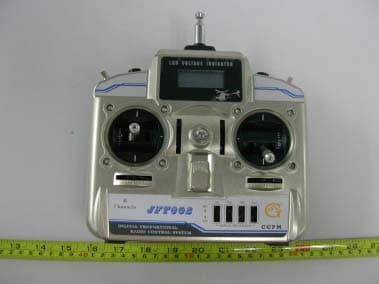
T5K602
May 16, 2007TRANSMITTER
Equipment Class
TNB - Licensed Non-Broadcast Station TransmitterT5KJFT401
Nov 10, 2006R/C Transmitter
Equipment Class
TNB - Licensed Non-Broadcast Station Transmitter