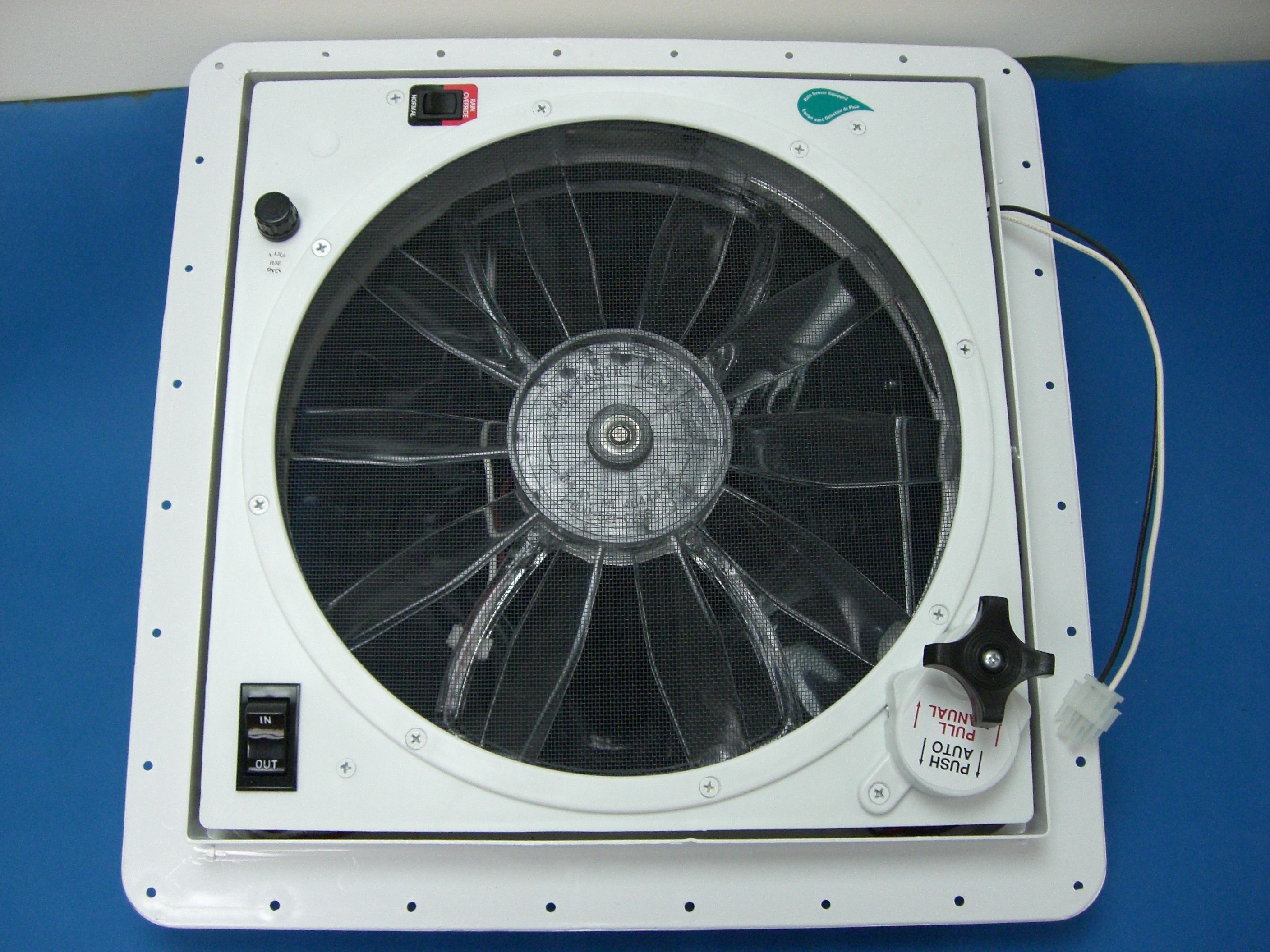
T5N6600Fantastic-Vent Model 6600 Hood Fan
KIB Enterprises Corp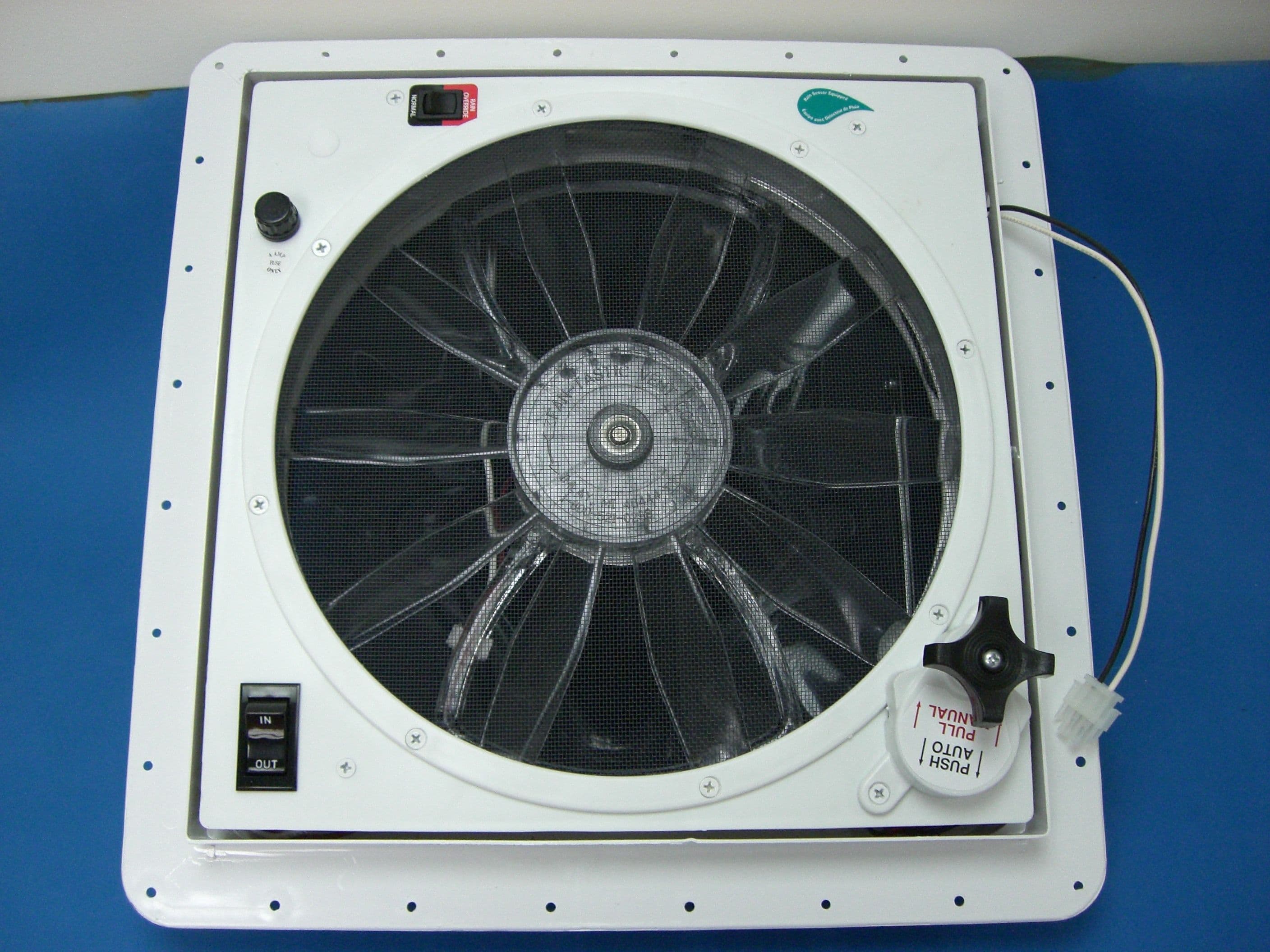
Click to zoom
Application Details
- Equipment Class
- DXT - Part 15 Low Power Transceiver, Rx Verified
- Date of Grant
- May 14, 2006
- Application Purpose
- Original Equipment
- Date of Application
- May 14, 2006
- Equipment Note
- Fantastic-Vent Model 6600 Hood Fan
- Frequency Range
- 2405.00000000 - 2405.00000000
- Company
- KIB Enterprises Corp
- Country
- United States
Documents & Files
Document Text
Text extracted from the exhibit documents filed with the FCC. Open a document above to read the original.
Users Manual
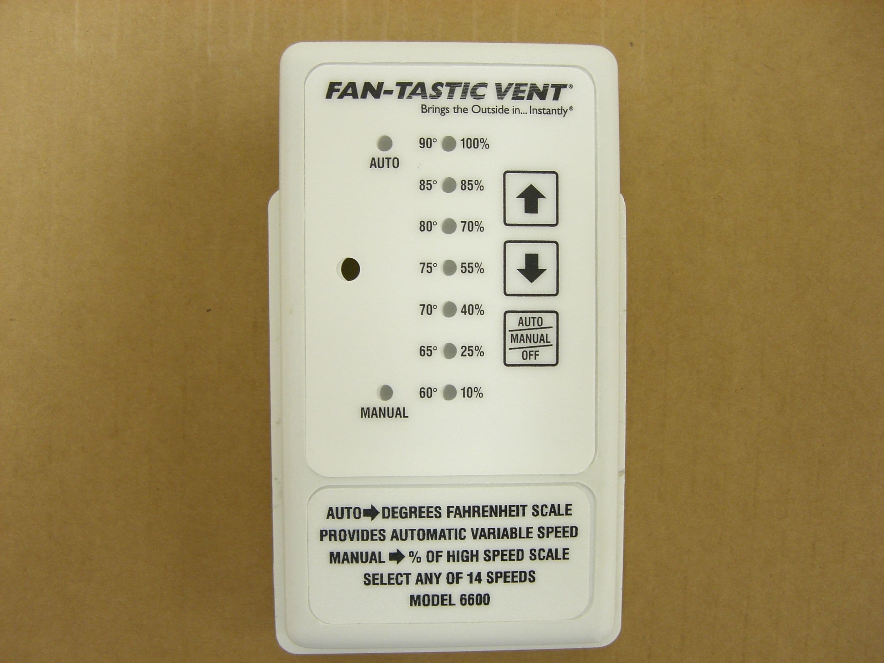
1.Select “AUTO”, the dome (lid) lifts automatically. Now press arrows “UP” to increase or “DOWN” to decrease and display thermostat setting. Press and hold arrow to scroll through all 14 temperature settings. Once temperature is set the controller will compare the actual ambient interior temperature to the current setting every 30 seconds and automatically increase or decrease fan blade speed to maintain set temperature inside coach. If temperature is set at 60º F fan motor will run at high speed regardless of inside temperature. Increase setting to a slightly warmer position and fan returns to automatic operation. CALIBRATION; when interior temperature cools 3º F below set temperature the fan blade shuts off (dome remains open) and does not restart until interior temperature raises 3º F. When interior temp raises 7º F above set point, fan blade will run at high speed until ambient interior temp cools to 7º F above set point or cooler. 5 seconds after last set point the display reverts to thermometer reading. 30 seconds after last set point, controller LED's shut of to save power and extend the life of the 2 AA batteries in RF controller. 2.Select “MANUAL”, the dome (lid) lifts automatically. Now press arrows “UP” to increase or “DOWN” to decrease fan blade speed and display current speed. To turn only the fan blade off, scroll down to 10% and then continue to push “DOWN” until fan motor shuts off. Press and hold arrow to scroll through all 14 settings (off to 100% or 100% to off). 3. Select “OFF”, dome closes shutting off fan motor, control lights go out but this system still draws fractional current (milliamps). For storage use battery disconnect. When fan is not used daily turn circuit to fan off or remove fuse from fuse holder in face of fan by pushing up on cap and ¼ turning to left. Fan-Tastic Vent Corp., 2083 S. Almont Ave.,Imlay City, MI. 48444. 1.800.521.0298, 8 to 5 EST 417 V ERTIC AL RF REM OT E (DIG ITAL )w/WA LL CR ADLE AUTO-AUTOMATIC SPEED IN AUTO MODE, 60º to 90º F SETTING LIGHTS LED. 1/2 SETTINGS LIGHT 2 LED'S IN 5 SEC.,AMB TEMP. SHOWS IN MANUAL MODE, 10 to 100% OF HIGH SPEED LIGHTS LED. 1/2 SETTING LIGHTS 2 LED'S. PUSH ARROWS UP OR DOWN TO CHANGE SETTINGS SELECT MODE BY PRESSING PAD ON WALL CONTROLLER AUTO MODE, TOP LEFT LED TURNS ON. MANUAL MODE, BOTTOM LEFT LED TURNS ON. OFF MODE, ALL LED'S ON CONTROL TURN OFF. 4.This fan is equipped with built in RAIN SENSOR. When dome (lid) is open and moisture contacts the sensor, the dome closes and turns fan blade motor off, if it is running. When the rain sensor dries, dome reopens and fan blade runs if fan was running when dome closed. Some conditions may require you to shut the rain sensor off. These conditions may include such things like taking a hot steamy shower, leaving dome open with fan blade motor slow or off at dew point, or perhaps keeping the fan on during a light to moderate rain shower. This is accomplished by identifying on the face of fan a two position mini rocker switch. Select RAIN SENSOR “OFF” (red print) to turn the rain sensor “OFF”. Return switch to “ON” (black print) before leaving fan unattended. 5.Some fans are equipped with a fan blade motor reversing switch. When so equipped pre- select OUT or IN on switch, if fan blade is set to run in either manual or auto mode, as dome opens fan motor turns on to pre-selected direction. When dome closes, either by selecting Off on controller or via moisture on rain sensor, fan blade motor shuts off. Anytime you reverse fan blade motor while system is in operation, select center, neutral position, allow fan blade to stop completely then select opposite direction restarting motor. The dome (lid) lift motor in your fan was designed to enable you to manually open/close dome (lid) in an emergency. Here's some other uses; NEW AT LIFT MOTOR FACTS; (eff. 6/21/01) The pull push knob must remain in “AUTO” position at all times. Pull down to “MANUAL” position to adjust dome height or in an emergency then push back (return) to “AUTO” immediately and slightly wiggle knob to insure it is properly locked. You can stop the dome partially open by applying, firm, opposite rotation to slowly turning knob while dome is opening, remember, FIRM PRESSURE! Open dome all the way during windy conditions. NOTICE: DO NOT LEAVE FAN IN ACTIVE MODE WHILE RIG IS STORED OR UNATTENDED FOR EXTNEDED PERIODS OF TIME – HIGH WINDS, OTHER UNUSUAL CONDITIONS OR OBSTRUCTIONS MAY PREVENT CLOSING: RESULTING LEAKAGE COULD CAUSE SERIOUS DAMAGE! Close all vents when using your Fan-tastic Vent. Slightly open window on shaded side of coach offers the most comfortable airflow, especially on hot, sunny days. Always position yourself between slightly open window and Fan-tastic Vent for maximum comfort. Remember, you direct airflow by slightly opening a window/s. FCC ID: T5N660 & FCC ID:T5N417 FCC Compliance Statement: This device complies with Part 15 of the FCC Rules. Operation is subject to the following two conditions: (1) this device may not cause harmful interference, and (2) this device must accept any interference received, including interference that may cause undesired operation. The users manual or instruction manual for an intentional or unintentional radiator shall caution the user that changes or modifications not expressly approved by the party responsible for compliance could void the user's authority to operate the equipment. In cases where the manual is provided only in a form other than paper, such as on a computer disk or over the Internet, the information required by this section may be included in the manual in that alternative form, provided the user can reasonably be expected to have the capability to access information in that form. Fan-Tastic Vent Corp., 2083 S. Almont Ave.,Imlay City, MI. 48444. 1.800.521.0298, 8 to 5 EST
Block Diagram
MC13191 Technical Data, Rev. 1.3 6Freescale Semiconductor Data Transfer Mode Figure3. System Level Block Diagram Figure4. MC13191 Packet Structure Analog Receiver MC13191 Frequency Generation Analog Transmitter Voltage Regulators Power Up Management Control Logic Buffer RAM SPI and GPIO Microcontroller SPI ROM (Flash) RAM CPUA/D Application Network MAC PHY Driver PreambleSFDFLIPayload DataFCS 4 bytes1 byte1 byte125 bytes maximum2 bytes Data Transfer Mode MC13191 Technical Data, Rev. 1.3 Freescale Semiconductor5 4.3 Transmit Path Description For the transmit path, the TX data that was previously stored in TX PAcket RAM is retrieved, formed into packets, spread, and then up-converted to the transmit frequency. Because the MC13191 is used in packet mode, data is processed as an entire packet. The data is first loaded into the TX buffer. The MCU then requests that the MC13191 transmit the data. The MCU is notified via an interrupt when the whole packet has successfully been transmitted. Figure2. MC13191 Simplified Block Diagram Phase Shift Modulator RST GPIO1 GPIO2 GPIO3 GPIO4 XTAL2 XTAL1 RFIN- RFIN+ PAO+ PAO- MOSI MISO SPICLK RXTXEN CE ATTN GPIO5 GPIO6 GPIO7 Receive Packet RAM Transmit Packet RAM 1 Transmit RAM Arbiter Receive RAM Arbiter PA VCO Crystal Oscillator Symbol Generation FCS Generation Header Generation Sequence Manager (Control Logic) VDDLO2 ÷4 256 MHz 2.45 GHz LNA 1st IF Mixer IF = 65 MHz 2nd IF Mixer IF = 1 MHzPMA Decimation Filter Matched Filter Baseband Mixer DCD CCA Packet Processor IRQ Arbiter 24 Bit Event Timer IRQ 16 MHz AGC Analog RegulatorVBATT Digital Regulator L Digital Regulator H Power-Up Control Logic Crystal Regulator VCO Regulator VDDINT Programmable Prescaler CLKO 2 Programmable Timer Comparators Synthesizer VDDD VDDVCO VDDA VDDLO1
Cover Letter(s)
Non-Conformities FCC ID: T5N6600 (Ref # E06-000113 -1) The items listed below represent requests for infor mation following review of this application. Furth er question may arise pending review of responses t o these items. OK # Non-Conformity or Comment Submitted Response Respondent / Date of Response X 1 FCC ID and FRN are not correct. Emailed response with correct FCC ID and FRN. 4/21/06 X 2 NOTE: It is highly recommended by the FCC that the request for confidentiality include references to both sections §0.457 and §0.459. Response to this item is optional. Updated confidentiality letter provided. 5/4/06 – F 2Labs X 3 The request for confidentiality includes refere nce to an FCC ID which does not match form 731 information. Please provide an updated label showing the requested FCC ID. Updated confidentiality letter provided. 5/4/06 – F 2Labs X 4 Please provide an operational description in ac cordance with 2.1033(b)(4); a brief description of the circuit functions of the d evice along with a statement describing how the device operates (including modul ation information)? This should include a description of the ground system a nd antenna (if any). Operational description provided 5/10/06 – F2 Labs X 5 Please provide a block diagram in accordance wi th 2.1033(b)(5) showing the frequency of all oscillators in the device includei ng the tuning range(s) and intermediate frequency(ies) each block. Block Diagram Provided 5/4/06 – F2Labs 6 Please provide a photo or drawing indicating lab el placement See below NC 5/10/06 – F2Labs X 7 Please provide a users manual incorporating the statement required by 15.21. Users manual provided . 5/4/06 – F2Labs 8 The frequency range listed in section 5 of the t est report does not meet the requirements of 15.35. Please supply demonstration of compliance down to 16MHz using a magnetic loop antenna. X 9 Note: 15.35 allows the use of duty cycle corre ction factors with no limit of 20dB; this is a common misinterpretation of the rul es. Specifically, the rules state that there is a de-facto peak limit of 20dB a bove the average limit such that , “peak emissions must not exceed 20dB above t he average limit.” Use of the full 37dB correction factor may be employed. No response necessary to this item None required. NA x 10 Due to the narrow pulse width of the transmitt er, was the measurement instrumentation verified for pulse desensitization or was a correction factor applied? Clarification provided. 5/4/06 – F2Labs Non-Conformities FCC ID: T5N6600 (Ref # E06-000113 -2) The items listed below represent requests for infor mation following review of this application. Furth er question may arise pending review of responses t o these items. OK # Non-Conformity or Comment Submitted Response Respondent / Date of Response X 1 The updated labels provided contain an improper character. The format of the FCC ID lable should contain a “:”. The labels provided include a “#”. Please revise. Updated label provided 5/12/06 – F2Labs The items indicated above must be submitted before processi ng can continue on the referenced application. Failure t o provide the requested information within 60 days may result in application dismissal pursuant to Section 2.917(c) and forfeiture of the fili ng fee pursuant to Section 1.1106.
External Photos
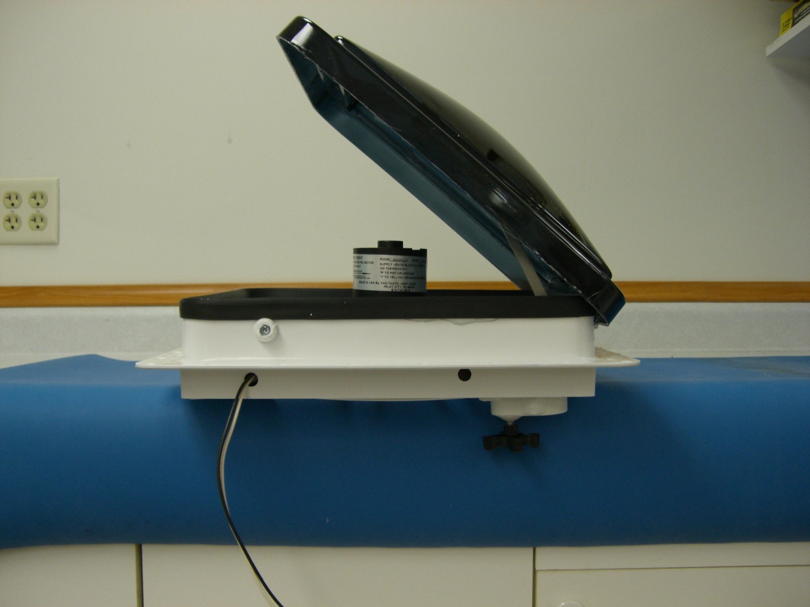
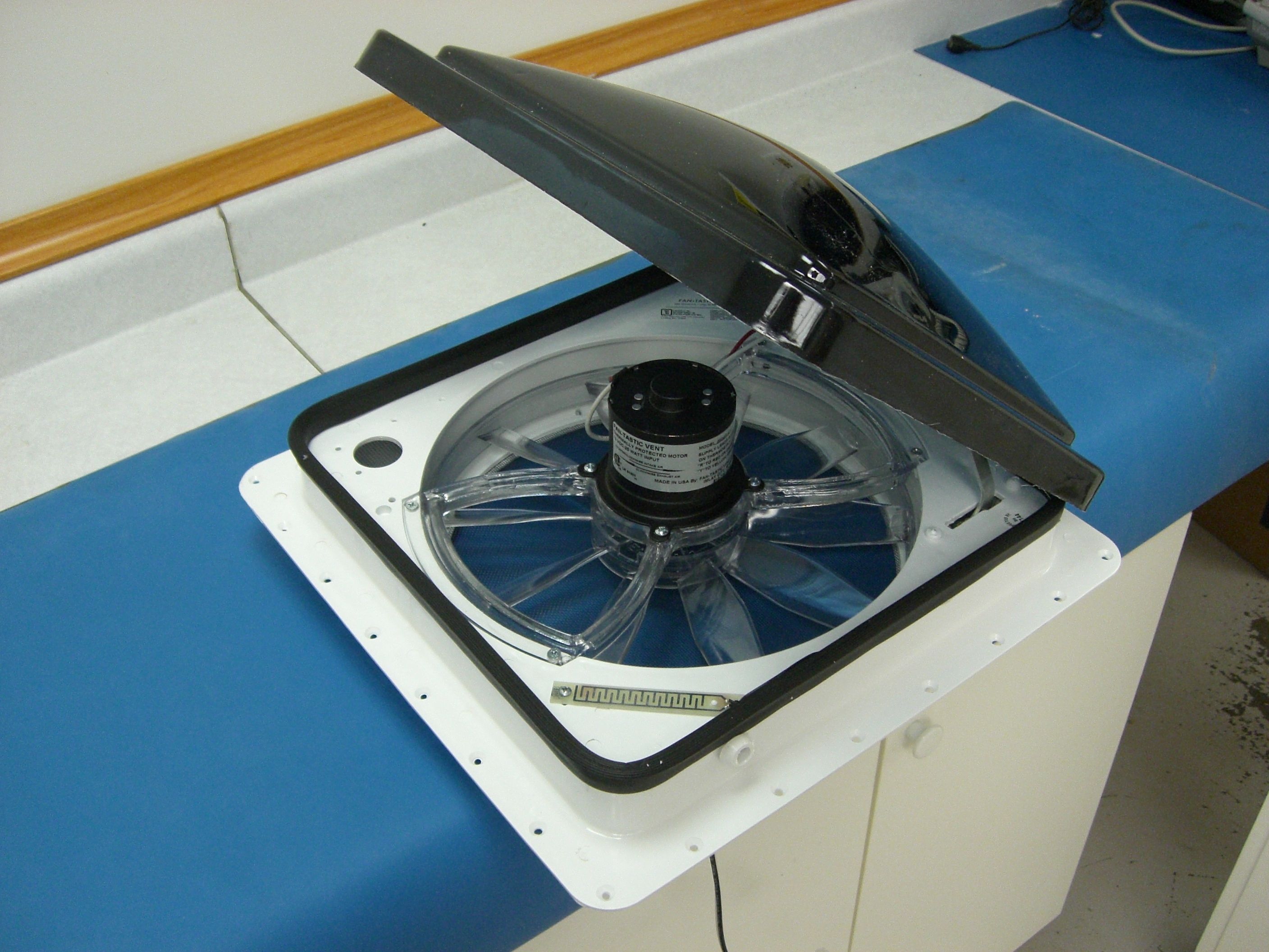
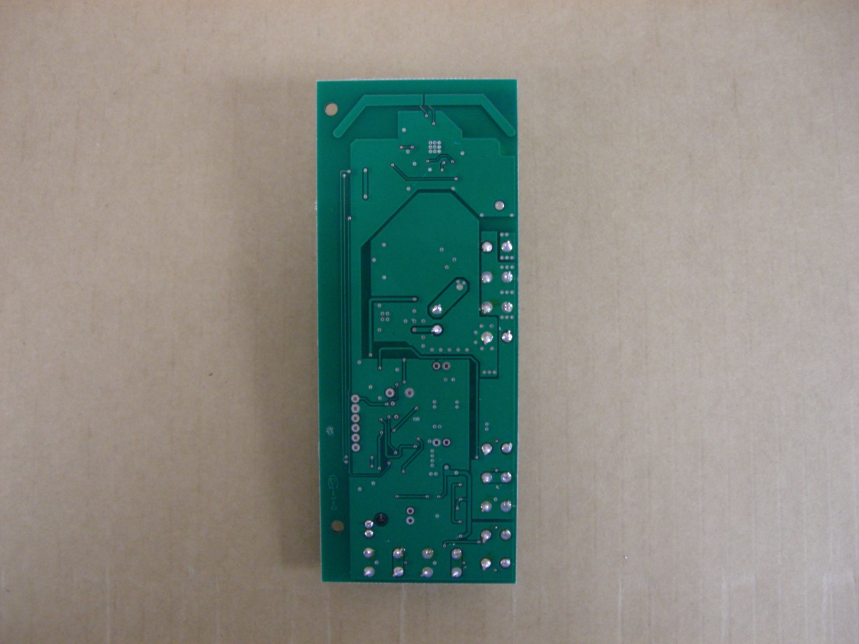
F2LQ2390-02E Page 1 of 3 May 10, 2006 PRODUCT PHOTOS Fan Unit: External View of Fan Cover (top) Fan Unit: External View – Interior of RV (fan bottom) Client: KIB Enterprises Order Number: F2LQ2390 EUT: Fan-Tastic Vent Ventilation Fan System for RV’s Report Number: F2LQ2390-02E Page 2 of 3 May 10, 2006 Fan Unit: Internal View – Circuit Board Exposed Fan Unit: Printed Circuit Board – Solder Side Client: KIB Enterprises Order Number: F2LQ2390 EUT: Fan-Tastic Vent Ventilation Fan System for RV’s Report Number: F2LQ2390-02E Page 3 of 3 May 10, 2006 Fan Unit: Printed Circuit Board – Component Side Fan Unit: Printed Circuit Board – Component Side, Close-up of RF Section
ID Label/Location Info
FCC ID: T5N6600 This label will be placed on the bottom side of the Model 6600 roof fan. This will make it visible for the floor. The FCC ID is 8pt 1" 0 . 2 5 "
Operational Description
Brief description of circuit functions for the FCC ID: T5N6600 5-10-2006 The MC107 circuit board is designed to go into Fantastic vents Model 6600 RF exhaust fan. 1)The MC107 function is to control the fan speed through voltage and current. To do this a simple buck regulator was implemented. 2)The MC107 is also responsible for controlling the Model 6600's automatic hood. This was implemented through a simple H-bridge. 3)The last function is the communications from the MC417 remote. To implement this a Freescale transceiver MC13191 was implemented. –Power supply: 12VDC –16 MHz crystal reference oscillator –Operating Frequency: 2.405GHz –Antenna: Printed Circuit board strip Line (Internal) Ground referenced to Battery ground –Offset-Quadrature Phase Shift Keying (O-QPSK) data in 2.0 MHz channels with 5.0 MHz channel spacing.
Test Report
This report shall not be duplicated except in full without the written approval of F-Squared Laboratories. EMC007 Rev. 1 Report Number: F2LQ2390-02E Page 1 of 18 Issue Date: April 7, 2006 F-Squared Laboratories 14333Kinsman Road Burton, OH 44021 (440) 834-8926 Fax: (440) 834-8914 For a Fan-Tastic Vent Ventilation Fan System for RV’s Manufacturer: Testing Laboratory: KIB Enterprises F-Squared Laboratories 53402 County Road 13 16740 Peters Road Elkhart, Indiana 46514 Middlefield, Ohio 44062 United States of America United States of America The Fan-Tastic Vent Ventilation Fan System model 6600R for RV’s consists of hand- held control transceiver model 417 and fan unit model 6600. This certification report specifically assesses the transmitter portion of the fan unit. The Fan Unit was found to comply with the requirements of the Federal Communications Commission outlined in the Federal Register CFR 47, Part 15.249. The products were received on March 21, 2006 and the testing was completed on March 24, 2006. Evaluation Conducted By: Report Reviewed By: Kenneth P. Klann John Harrington EMC Engineer EMC Technical Manager Certification Test Report Client: KIB Enterprises Order Number: F2LQ2390 EUT: Fan-Tastic Vent Ventilation Fan System for RV’s EMC007 Rev. 1 Report Number: F2LQ2390-02E Page 2 of 18 Issue Date: April 7, 2006 Table of Contents Section Title Page Cover Page 1 Table of Contents 2 1 Engineering Statement 3 2 List of Measurement Instrumentation 4 3 EUT Information and Data 5 4 EUT Configuration and Cables 7 5 FCC Part 15.249 8 6 Figures – Spectral Data Plots 10 7 Photos/Exhibits – Product Photos, Test Setups 12 Client: KIB Enterprises Order Number: F2LQ2390 EUT: Fan-Tastic Vent Ventilation Fan System for RV’s EMC007 Rev. 1 Report Number: F2LQ2390-02E Page 3 of 18 Issue Date: April 7, 2006 1. ENGINEERING STATEMENT This report has been prepared on behalf of KIB Enterprises to provide documentation for the testing described herein. The test results found in this test report relate only to the items tested. 1.1 Equipment Under Test: KIB Enterprises Fan Unit Transmitter FCC ID: T5N6600 1.2 Trade Name: Fan-Tastic Vent 1.3 Model: KIB Enterprises Model: 6600 1.4 Power Supply: 12VDC (connects to RV 12 Volt supply) 1.5 Applicable Rules: CFR 47, Part 15.249, subpart C 1.6 Equipment Category: Radio Transmitter-Control 1.7 Operating Frequency: 2.405 GHz 1.8 Antenna: Printed Circuit Board Strip Line (Internal) 1.9 Measurement Location: F-Squared Laboratories in Middlefield, Ohio. Site description and attenuation data are on file with the FCC's Sampling and Measurement Branch at the FCC Laboratory in Columbia, MD. 1.10 Measurement Procedure: All measurements were performed according to the 2003 version of ANSI C63.4 and recommended practices of FCC 15.35. 1.11 Uncertainty Budget: Radiated Emissions - Combined Uncertainty + 2.24 dB; Extended Uncertainty + 4.48 dB. Client: KIB Enterprises Order Number: F2LQ2390 EUT: Fan-Tastic Vent Ventilation Fan System for RV’s EMC007 Rev. 1 Report Number: F2LQ2390-02E Page 4 of 18 Issue Date: April 7, 2006 1.12 Engineering Certification: The undersigned of this report hereby state that the measurements shown in this application were made in accordance with the procedures indicated, and that the energy emitted by this equipment was found to be within the limits. The undersigned assume full responsibility for the accuracy and completeness of these measurements and further state that, on the basis of the measurements made, the equipment tested is capable of operation in accordance with the requirements of Part 15.249 of the FCC Rules under normal use and maintenance. 2. LIST OF MEASUREMENT INFORMATION Equipment Type Manufacturer Model Serial Number Calibration Due Date Thermohygrometer Oakton 32230-80 001 June 7, 2006 OATS Compliance Labs N/A 001 Aug. 24, 2006 Receiver Rohde & Schwarz Display, EASI-0-804- 8932-52; RF Unit, ESMI- RF 1032-5640-53 84982/015; 849152/005 Mar. 31, 2006 Antenna 2-OATS Sunol Sciences JB1 A101101 Apr. 15, 2006 Horn Antenna Emco 3115 9809-5580 Apr. 6, 2006 Pre-Amplifier Hewlett Packard 83006A 310A00500 Oct. 20, 2006 Client: KIB Enterprises Order Number: F2LQ2390 EUT: Fan-Tastic Vent Ventilation Fan System for RV’s EMC007 Rev. 1 Report Number: F2LQ2390-02E Page 5 of 18 Issue Date: April 7, 2006 3. EQUIPMENT UNDER TEST (EUT) INFORMATION AND DATA 3.1 Test Item Condition: The equipment to be tested was received in good condition. 3.2 Testing Algorithm: The Fan Unit is designed for operation on a single frequency (2.405 GHz). Ultimately, the unit will transmit only four pulse groups spaced at approximately 450mS intervals, under certain error conditions (note, the Fan Unit transmission is not currently supported in firmware; thus, current units do not transmit). The manufacturer indicates that the same pulse transmission characteristic will be implemented as used in the Hand-Held Control. The Fan Unit will generate a pulse grouping as shown in the Spectral Plot in Figure 1). The Fan Unit RF components are based on the Freescale (Motorola) MC13191 chip. For testing purposes, modified Fan Units were supplied that transmit a continuous pulse train spaced at intervals of approximately 100mS (see Spectral Plot in Figure 2). Two modified units were supplied: 3.2.a. A unit equipped with a BNC connector for direct connection to the measuring receiver (used to determine the significant harmonic and spurious frequencies for examination on the Open Area Test Site). 3.2.b A unit using the standard Printed Circuit Strip Line Antenna for final measurements on the Open Area Test Site (OATS). 3.3 Radiated Emission Testing on Open Area Test Site (OATS): The EUT was tested at a distance of 1.0 or 3.0 meters. The emissions were maximized by rotating the table and raising/lowering the antenna mounted on a 4.0 meter mast.* Both horizontal and vertical field components were measured. The output of the antenna was connected to the input of the receiver and emissions were…
Text truncated - open the document above for the full version.
Test Setup Photos
F2LQ2390-02E Page 1 of 4 May 10, 2006 PHOTOGRAPHS - TEST SETUPS Fan Unit: Direct Connection to Receiver (RF Antenna Conducted) Client: KIB Enterprises Order Number: F2LQ2390 EUT: Fan-Tastic Vent Ventilation Fan System for RV’s F2LQ2390-02E Page 2 of 4 May 10, 2006 Orthogonal Positions of Fan Unit –Upright #1 Orthogonal Positions of Fan Unit – Upright #2 TOGRAPH OF POWER SUPPLY – Whole View Client: KIB Enterprises Order Number: F2LQ2390 EUT: Fan-Tastic Vent Ventilation Fan System for RV’s F2LQ2390-02E Page 3 of 4 May 10, 2006 Orthogonal Positions of Fan Unit – On Back Client: KIB Enterprises Order Number: F2LQ2390 EUT: Fan-Tastic Vent Ventilation Fan System for RV’s F2LQ2390-02E Page 4 of 4 May 10, 2006 Overall Test Setup on OATS
Contact Information
Applicant
John G Brown(Engineer)
Technical Contact
KIB EnterprisesJohn Brown
[email protected]574-262-0518
53402 County Road 13 · Elkhart, Indiana · United States
Test Firm
F-Squared LaboratoriesWendy Fuster
Technical Specifications
| # | Rule Parts | Frequency Range | Power Output |
|---|---|---|---|
| 1 | 15C | 2.40 GHz - 2.40 GHz | - |
Other Applications from KIB Enterprises Corp
T5N417
May 14, 2006Fantastic-Vent 417RF Hood Fan Remote
Equipment Class
DXT - Part 15 Low Power Transceiver, Rx Verified