FCCID.CO- FCC ID Database
HomeCompaniesEquipment ClassesSearch

Β© 2026 FCC ID Database. All rights reserved.

AboutContactData sourced from FCC public records
  1. Home/
  2. De Amertek Corporation/
  3. T6FWRLSS-STAT-002

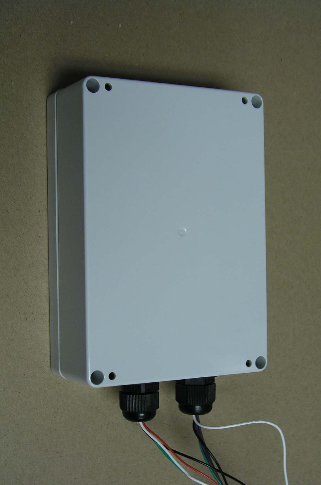
T6FWRLSS-STAT-002Wireless Remote Sender

De Amertek Corporation
Wireless Remote Sender - FCC ID T6FWRLSS-STAT-002 - De Amertek Corporation
Click to zoom

Application Details

Equipment Class
DSS - Part 15 Spread Spectrum Transmitter
Date of Grant
Jul 09, 2006
Application Purpose
Original Equipment
Date of Application
Jul 09, 2006
Equipment Note
Wireless Remote Sender
Frequency Range
902.79700000 - 927.09400000
Company
De Amertek Corporation
Country
United States

Documents & Files

Select a file to view

Users Manual

β†—

Cover Letter(s)

β†—

External Photos

β†—

ID Label/Location Info

β†—

Internal Photos

β†—

Test Report

β†—

Test Setup Photos

β†—

Document Text

Text extracted from the exhibit documents filed with the FCC. Open a document above to read the original.

Users Manual

Confidential Property of B&S Home Power Products 5/4/2006 12:00pm 11/30/2005 System Ready Main Menu – Press Any Key Wireless StatStation Wireless StatStation LCD Display LCD Display - - Infocenter Infocenter Specifications Specifications Confidential Property of B&S Home Power Products 5/4/2006 General Specifications General Specifications β€’ Font style to be Myriad Pro Condensed or Antique Olive 2 unless specified. β€’ Font size to be 8 or 10 unless specified. β€’ 2.5mm jack for 120volt wall wart. β€’ Receiver to have 4 AA batteries. β€’ Operating Temperature: 40 ΒΊF – 110 ΒΊF β€’ After 30 seconds of no interaction, unit defaults to Idle Screen. β€’ Backlight on during any key touch. Off after 30 seconds on no interaction. β€’ Range from transmitter: ~200ft. β€’ Frequency of transmitter: 900mHz range with Frequency hopping β€’ Audible Alarm on low from factory β€’ Date Format : mm/dd/yyyy β€’ Time Format : hh:mm am/pm β€’ Investigate Multi-Lingual Format Confidential Property of B&S Home Power Products 5/4/2006 System System Overview Overview Confidential Property of B&S Home Power Products 5/4/2006 HOME STANDBY SYSTEM HOME STANDBY SYSTEM WITH STAT WITH STAT - - STATION STATION Stand-By Generator Display Unit Utility Power Remote Sender Unit R F S i g n a l Confidential Property of B&S Home Power Products 5/4/2006 Single Wire Communication to Transfer Switch Control 240VAC to House GENERATOR CONTROL UNIT Confidential Property of B&S Home Power Products 5/4/2006 240 VAC from Utility Communication Bus to Generator Control Remote Sender Unit Optional: Phone Dialer Ethernet Hub Etc. 240 VAC from Generator 240 VAC to House Automatic Transfer Switch House Breaker Box / Power Distribution Center Power Distribution Center Power Distribution Center Confidential Property of B&S Home Power Products 5/4/2006 REMOTE SENDER UNIT  Communicates with Display Unit via RF  Communicates with Transfer Switch Control and Home Stand-By Control systems via Hardwire  Optional: Output for Phone Dialer or Ethernet Hub  RF: 900MHz with Frequency Hopping  Sealed Nema-3 Housing (Optional) Confidential Property of B&S Home Power Products 5/4/2006 REMOTE DISPLAY UNIT 12:00pm 11/30/2005 System Ready Main Menu – Press Any Key  Communicates with Sender Unit via RF  Displays System Status:  Loss of Utility  Generator Operation  Home Power Usage  Exercise Mode  Maintenance Reminders  System Alarms with Audible Alert  RF: 900MHz with Frequency Hopping  Range: 100’ from Remote Sender Unit  Desktop Case Design Confidential Property of B&S Home Power Products 5/4/2006 Idle Screen Idle Screen 12:00pm 11/30/2005 System Ready Main Menu – Press Any Key Logo does not have to be color, black & white ok Should always state the current status of the system, not the menu This is the Activate Button 2 color LED. Red & Green, with Green being lit during all normal operation Confidential Property of B&S Home Power Products 5/4/2006 Utility Power Outage Screen Utility Power Outage Screen 12:00pm 11/30/2005 Utility Power Outage Utility Power Outage Utility Power Loss Please Wait... Home Generator System Starting... Backlight On after 5 sec delay, On for 2 minutes Main Menu – Press Any Key Displays after backup system recognizes utility outage and is attempting to start generator Confidential Property of B&S Home Power Products 5/4/2006 Backup Power Mode Screen Backup Power Mode Screen 12:00pm 11/30/2005 Generator Power Mode Generator Power Mode Generator Running 5000 Watts Duration Display Running Duration Here. Days, Hours, Minutes Main Menu – Press Any Key 500 watt increments Should always be displayed when in generator mode, even if other screen shows some other information Confidential Property of B&S Home Power Products 5/4/2006 Backup Power Mode Screen Backup Power Mode Screen 12:00pm 11/30/2005 Generator Power Mode Generator Power Mode Utility Power Present... Generator system preparing to transfer to Utility Power... While Generator system monitors stability of Utility Power, this is displayed until transfer to Utility Power occurs Main Menu – Press Any Key When Utility Power returns, system should signal this Confidential Property of B&S Home Power Products 5/4/2006 Backup Power Mode Screen Backup Power Mode Screen 12:00pm 11/30/2005 System Ready Generator Cool-down Utility Power Online... Generator system preparing to shutdown... While Generator system cools down before shutdown, this should be displayed After Generator has shutdown after its cool-down cycle, return to Idle Screen automatically Main Menu – Press Any Key When Utility Power has been restored via transfer, system should signal this Confidential Property of B&S Home Power Products 5/4/2006 Exercise Mode Screen Exercise Mode Screen 12:00pm 11/30/2005 Exercise Mode Exercise Mode Generator Exercise Time Remaining _ _ minutes _ _ min Main Menu – Press Any Key Should count down from initial start of exercise Should always be displayed when in exercise mode, counting down, even if other screen shows some other information Confidential Property of B&S Home Power Products 5/4/2006 Alarm Alert Screen Alarm Alert Screen 12:00pm 11/30/2005 System Alert Mode System Alert Mute Alarm LED Flashes Red, 1 second on, 1 second off System alert code here, No flashing on/off. Shows multiple alerts (if present) System Alerts : β€’ 8 normal faults coming from Standby system β€’ Maintenance Required Confidential Property of B&S Home Power Products 5/4/2006 Main Menu Screen Main Menu Screen 12:00pm 11/30/2005 System Ready Main Menu System Settings System Sync Return to Idle Screen Maintenance Schedule History Confidential Property of B&S Home Power Products 5/4/2006 History Screen History Screen 12:00pm 11/30/2005 History Return Total Run Time : _ _ _ _ hrs Next Exercise : _ _ _ _ hrs Display Running Watts & Duration Here if in Generator Power Mode or Display Exercise Mode & Duration if in Exercise Mode System Ready Confidential Property of B&S Home Power Products 5/4/2006 Maintenance Screen Maintenance Scr…

Text truncated - open the document above for the full version.

Cover Letter(s)

May 4, 2006 FCC ID: T6FWRLSS-STAT-002 Request for Confidentiality In accordance with 47 C.F.R. Section 0.459, we, De Amertek Corporation, hereby request confidentiality for the block diagram, schematic and product description presented for certification. In support of the Request for Confidentiality, the following is stated: Enclosed within this application is technical information which we deem to be trade secrets and proprietary. If made public, the information might be used to our disadvantage. To assist in assuring that we receive the full value of our product and protect its competitive posture, we respectfully request this grant of confidentiality. Daniel Anderson Director Executive Office De Amertek Corporation 300 Windsor Drive Oak Brook, IL 60523 (630) 572-0800

ID Label/Location Info

12:00pm 11/30/200 5 System Ready Main Menu – Press Any Key Wireless StatStation FCC ID Labels FCC ID: T6FWRLSS-STAT-001S/N: 061250045 FCC ID: T6FWRLSS-STAT-002S/N: 061250045 S/N: 061250045 = YYDDD####YY = Last 2 Digits of the YearDDD = Day Number (365 days)#### = Serial Number of the units built that day. Note: 5/4/06 This device complies with part 15 of the FCC Rules. Operation is subject to the following two conditions: (1) This device may not cause harmful interference, and (2) this device must accept any interference received, including interference that may cause undesired operation. This device complies with part 15 of the FCC Rules. Operation is subject to the following two conditions: (1) This device may not cause harmful interference, and (2) this device must accept any interference received, including interference that may cause undesired operation.

Test Report

Elite Electronic Engineering Inc. 1516 Centre Circle Downers Grove, IL 60515 Tel : (630) 495-9770 Fax: (630) 495-9785 www.elitetest.com Engineering Test Report No. 36480-01 Measurement of RF Interference from a Wireless Stat-Station Remote Sender (RS) Transciever For : DeAmertek Corporation Oak Brook, IL P.O. No. : P23534 Date Received : April 6, 2006 Date Tested : April 10-14, 2006 Test Personnel : Richard E. King Specification : FCC "Code of Federal Regulations" Title 47, Part 15, Subpart B for receivers and Subpart C, Section 15.247 for Frequency Hopping Spread Spectrum Intentional Radiators Operating within the 902-928MHz band. Test Report By : Richard E. King EMC Engineer Approved By : Raymond J. Klouda Registered Professional Engineer of Illinois - 44894 Engineering Test Report No. 36480-01 THIS REPORT SHALL NOT BE REPRODUCED, EXCEPT IN FULL, WITHOUT THE WRITTEN APPROVAL OF ELITE ELECTRONIC ENGINEERING INC. Page 2 of 66 TABLE OF CONTENTS PARAGRAPH DESCRIPTION OF CONTENTS PAGE NO. 1.0 INTRODUCTION................................................................................................................................................ 4 1.1 Description of Test Item.................................................................................................................................... 4 1.2 Purpose ............................................................................................................................................................. 4 1.3 Deviations, Additions and Exclusions ............................................................................................................... 4 1.4 Applicable Documents ...................................................................................................................................... 4 1.5 Laboratory Identification................................................................................................................................... 4 1.6 Laboratory Conditions..................................................................................................................................... 5 2.0 TEST ITEM SETUP AND OPERATION............................................................................................................. 5 2.1 Power Input...................................................................................................................................................... 5 2.2 Grounding......................................................................................................................................................... 5 2.3 Peripheral Equipment........................................................................................................................................ 5 2.4 Interconnect Cables........................................................................................................................................... 5 2.5 Operational Mode ............................................................................................................................................. 5 3.0 TEST EQUIPMENT............................................................................................................................................. 5 3.1 Test Equipment List .......................................................................................................................................... 5 3.2 Calibration Traceability ................................................................................................................................... 5 4.0 REQUIREMENTS, PROCEDURES AND RESULTS.......................................................................................... 5 4.1 Powerline Conducted Emissions ..................................................................................................................... 5 4.2 Radiated Measurements................................................................................................................................... 6 4.2.1 Receiver.................................................................................................................................................... 6 4.2.2 Transmitter ............................................................................................................................................... 8 4.3 Carrier Frequency Separation ......................................................................................................................... 9 4.4 Number of Hopping Frequencies..................................................................................................................... 9 4.5 Time of Occupancy ........................................................................................................................................ 9 4.6 20dB Bandwidth ............................................................................................................................................ 10 4.7 Peak Output Power ........................................................................................................................................ 10 4.8 Bandedge Compliance ................................................................................................................................... 11 5.0 CONCLUSIONS................................................................................................................................................. 12 6.0 CERTIFICATION .............................................................................................................................................. 12 7.0 ENDORSEMENT DISCLAIMER...................................................................................................................... 12 TABLE I - EQUIPMENT LIST.............................................................................................................................. 13 Engineering Test Report No. 36480-0…

Text truncated - open the document above for the full version.

Test Setup Photos

Engineering Test Report No. 36480-01 Figure 2 Powerline Conducted Emissions 150kHz – 30MHz Page 15 of 66 Engineering Test Report No. 36480-01 Figure 3 Radiated Emissions – Horizontal Polarization Radiated Emissions – Vertical Polarization Page 16 of 66

Contact Information

Applicant

Dan Anderson(Director of Executive Office)
[email protected]630-572-0800Fax: 630-572-1183

Technical Contact

De Amertek CorporationPatrick J Forster
[email protected]630-572-0800

300 Windsor Drive Β· Oak Brook, Illinois Β· United States

Non-Technical Contact

De Amertek CorporationPatrick J Forster
[email protected]630-572-0800

Test Firm

Elite Electronic Engineering Co.Daniel Crowder
[email protected]630-495-9770Fax: 630-495-9785

Technical Specifications

#Rule PartsFrequency RangePower Output
115C902.797 MHz - 927.094 MHz3.00 mW
Confidentiality
Long Term
Grant Notes
The antenna(s) used for this transmitter must not be co-located or operating in conjunction with any other antenna or transmitter End-users must be provided with specific operating instructions for satisfying RF exposure compliance requirements.

Other Applications from De Amertek Corporation
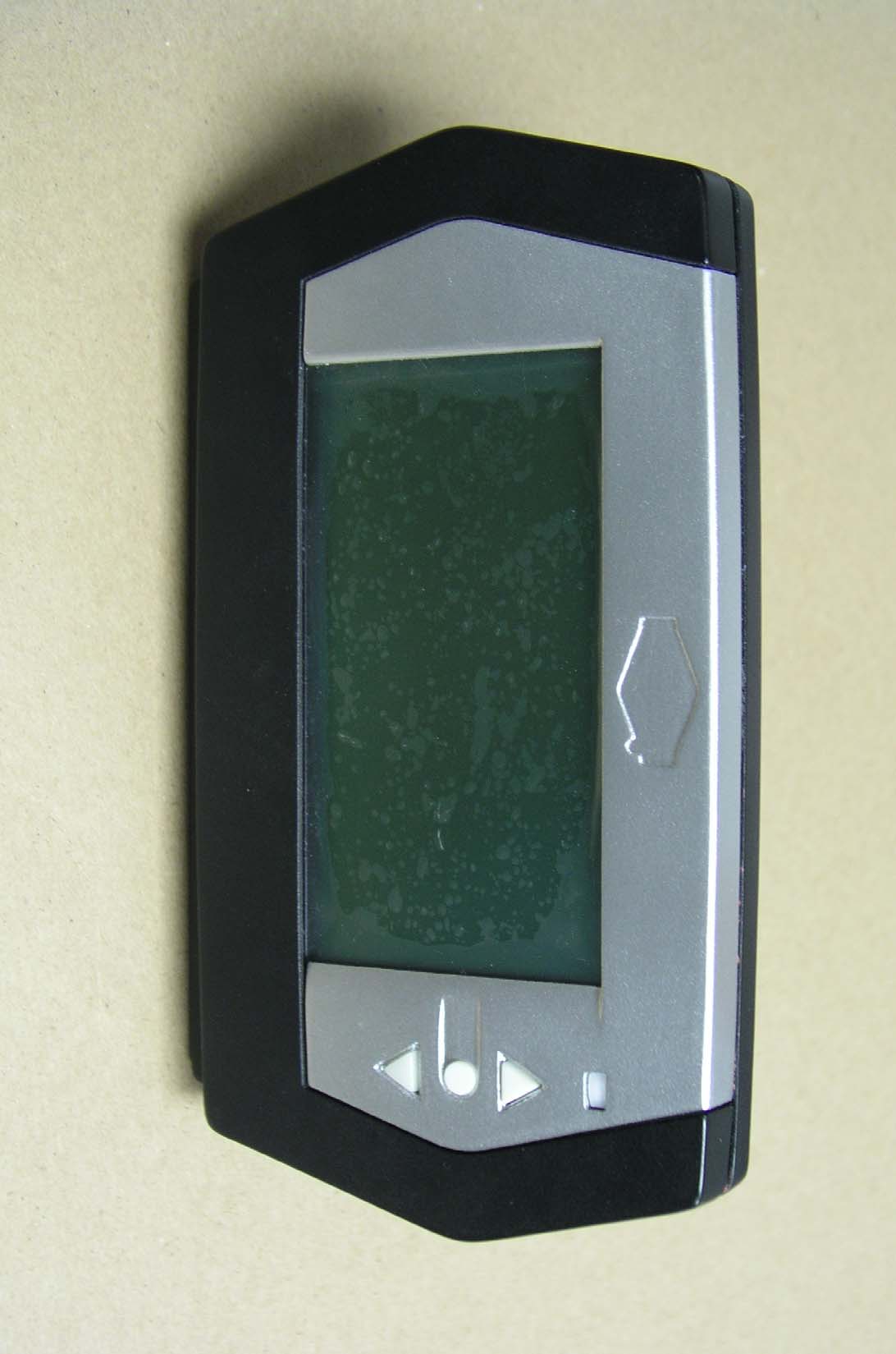
Wireless Display Center - FCC ID T6FWRLSS-STAT-001 - De Amertek Corporation
T6FWRLSS-STAT-001

Wireless Display Center

Jul 09, 2006

Equipment Class

DSS - Part 15 Spread Spectrum Transmitter