T7HR4024DECT 6.0 Wireless Relay Station
RTX Hong Kong Ltd.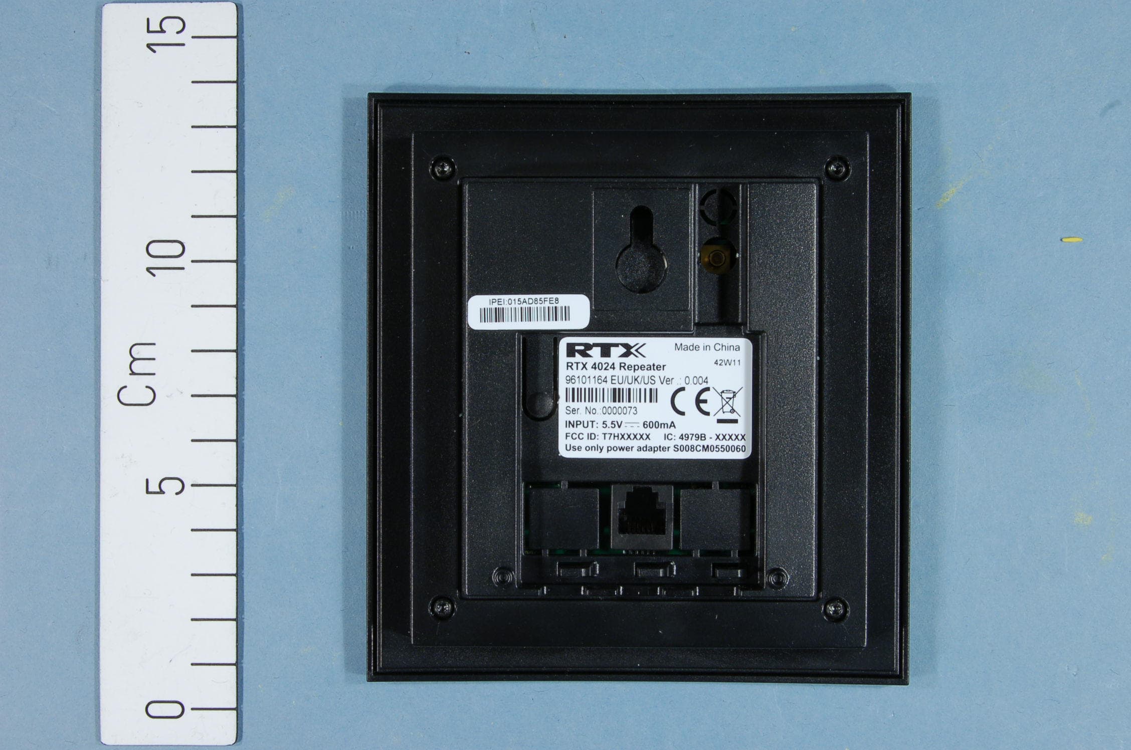
Click to zoom
Application Details
- Equipment Class
- PUB - Part 15 Unlicensed PCS Base Station
- Date of Grant
- Apr 15, 2012
- Application Purpose
- Original Equipment
- Date of Application
- Apr 11, 2012
- Equipment Note
- DECT 6.0 Wireless Relay Station
- Frequency Range
- 1921.53600000 - 1928.44800000
- Company
- RTX Hong Kong Ltd.
- Country
- Hong Kong
Documents & Files
Document Text
Text extracted from the exhibit documents filed with the FCC. Open a document above to read the original.
Users Manual
Page 1 of 4 How to register repeater and firmware update over air. Register repeater 1. Login to base. 2. Select page “Repeaters” 3. Select “Add Repeater” 4. Select “DECT Sync mode” Manually: User controlled by manually assign “Repeater RPN” and “DECT sync source RPN” Local Automatical: Repeater controlled by auto detects best base signal and auto assign RPN. Chaining Automatical: Base controlled by auto detects best base or repeater signal and auto assign RPN. Manually mode Page 2 of 4 Select “RPN” SINGLE CELL SYSTEM: The base has always RPN00, first repeater will then be RPN01, second repeater RPN02 and third RPN03 (3 repeaters maximum per base) MULTI CELL SYSTEM: Bases are increment by 2^2 in hex, means first base RPN00 second base RPN04 etc., in between RPN01, 02, 03 addressed for repeaters at Primary base and 05, 06, 07 addressed for Secondary base (3 repeaters maximum per base) Select “DECT sync source” What base or repeater the repeater has to be synchronize on. Example of 2 bases in chain and 2 repeater chains. 3 repeaters chained at Primary base. Repeater1 Repeater2 Repeater3 3 repeaters chained at Secondary base. Repeater4 Repeater5 Repeater6 To edit repeater mode - select index. Page 3 of 4 Local Automatical Repeater controlled by auto detects best base signal and auto assign RPN. Repeater on base only, repeater on repeater (chain) not supported. Repeater RPN dynamic assigned in base RPN range. Chaining Automatical Base controlled by auto detects best base or repeater signal and auto assign RPN. Repeater on base or repeater, repeater on repeater (chain) supported. Repeater RPN static assigned from base. 5. Check “Idx 0” 6. Select link “Register Repeater(s)” (Base open 5 minutes for repeater registration) 7. Power on repeater placed near base. (default registration mode if production unit) LED green double flash: Registration mode - if not then press reset button for 4 seconds. LED green steady: Within a minute the repeater should be registered successful. LED red steady: Registration timeout, press reset button 4 sec. or power cycle repeater. To see Repeater signal strength in handset enable “Site survey mode” via hidden menu. Press key: [MENU] *7378423* Handset scans and list from left the RPN of base and repeater, below RPN is signal strength in –dbm. Successful registration. Page 4 of 4 Firmware update (FWU) Repeater 1. TFTP firmware server, create directory “DECT4024” at same root as “Beatus” directory. 2. Copy Repeater firmware “DECT4024_Vxxxx.fwu” to directory “DECT4024” 3. Select page “Firmware Update” 4. Set “Firmware update server address” and “Firmware path” according to TFTP server installation. 5. Type “DECT4024” firmware version. 6. Press “Save” 7. Select page “Repeaters” 8. Select “Refresh” (Update FWU progress and FW Info) After approx. 15 minutes FWU reached 100% and repeater reboots in new firmware version with progress complete.
Users Manual
Additional Information RTX4024 Important safety information Charge the repeater only in combination with RTX4024 Repeater and the Ten Pao adapter S008CM0550060 that comes with the product. Plug the Ten Pao AC/DC adaptor in a wall outlet socket near the equipment for easy access/removal of the AC/DC adaptor. Sensitive Electronic Environment Any radio-based equipment can potentially cause interference with other equipment and can be interfered from other equipment. This also applies for DECT equipment. However due to the very low transmission power level the chances for interference are very small. Research proves that operational DECT Repeaters normally don’t influence electronic equipment however some precautions must be taken into account for sensitive electronic equipment e.g. sensitive laboratory equipment. When DECT repeaters operate in straight nearness of sensitive electronic equipment incidental influence can appear. You are advised not to place the DECT repeaters on or close (less than 10cm) to this kind of equipment, even in standby mode. Please also use the other documentation supplied with the various parts of your telephone system. Product disposal information For countries in the European Union The symbol depicted here has been affixed to your product in order to inform you that electrical and electronic products should not be disposed of as municipal waste. Electrical and electronic products including the cables, plugs and accessories should be disposed of separately in order to allow proper treatment, recovery and recycling. These products should be taken to a designated facility where the best available treatment, recovery and recycling techniques are available. Separate disposal has significant advantages: valuable materials can be re-used and it prevents the dispersion of unwanted substances into the municipal waste stream. This contributes to the protection of human health and the environment. Please be informed that a fine may be imposed for illegal disposal of electrical and electronic products via the general municipal waste stream. In order to facilitate separate disposal and environmentally sound recycling, arrangements have been made for local collection and recycling. In case your electrical and electronic products need to be disposed of please refer to your supplier or the contractual agreements that your company has made upon acquisition of these products. For countries outside the European Union Disposal of electrical and electronic products in countries outside the European Union should be done in line with the local regulations. If no arrangement has been made with your supplier, please contact the local authorities for further information. Regulatory information Europe Declaration of conformity Česky “RTX Products” tímto prohlašuje, že tento “RTX4024” je ve shodě se základními požadavky a dalšími příslušnými ustanoveními směrnice 1999/5/ES. Dansk Undertegnede “RTX Products” erklærer herved, at følgende udstyr “RTX4024” overholder de væsentlige krav og øvrige relevante krav i direktiv 1999/5/EF. Deutsch Hiermit erklärt “RTX Products”, dass sich das Gerät “RTX4024” in Übereinstimmung mit den grundlegenden Anforderungen und den übrigen einschlägigen Bestimmungen der Richtlinie 1999/5/EG befindet. Eesti Käesolevaga kinnitab “RTX Products” seadme “RTX4024” vastavust direktiivi 1999/5/EÜ põhinõuetele ja nimetatud direktiivist tulenevatele teistele asjakohastele sätetele. English Hereby, “RTX Products”, declares that this “RTX4024” is in compliance with the essential requirements and other relevant provisions of Directive 1999/5/EC. Español Por medio de la presente “RTX Products” declara que el “RTX4024” cumple con los requisitos esenciales y cualesquiera otras disposiciones aplicables o exigibles de la Directiva 1999/5/CE. Ελληνική ΜΕ ΤΗΝ ΠΑΡΟΥΣΑ Η “RTX Products” ΔΗΛΩΝΕΙ ΟΤΙ “RTX4024” ΣΥΜΜΟΡΦΩΝΕΤΑΙ ΠΡΟΣ ΤΙΣ ΟΥΣΙΩΔΕΙΣ ΑΠΑΙΤΗΣΕΙΣ ΚΑΙ ΤΙΣ ΛΟΙΠΕΣ ΣΧΕΤΙΚΕΣ ΔΙΑΤΑΞΕΙΣ ΤΗΣ ΟΔΗΓΙΑΣ 1999/5/ΕΚ. 1 Français Par la prsente “RTX Products” déclare que l’appareil “RTX4024” est conforme aux exigences essentielles et aux autres dispositions pertinentes de la directive 1999/5/CE. Íslenska Hér með lýsir “RTX Products” yfir því að “RTX4024” er í samræmi við grunnkröfur og aðrar kröfur, sem gerðar eru í tilskipun 1999/5/EC. Italiano Con la presente “RTX Products” dichiara che questo “RTX4024” è conforme ai requisiti essenziali ed alle altre disposizioni pertinenti stabilite dalla direttiva 1999/5/CE. Latviski Ar šo “RTX Products” deklarē, ka “RTX4024” atbilst Direktīvas 1999/5/EK būtiskajām prasībām un citiem ar to saistītajiem noteikumiem. Lietuvių Šiuo “RTX Products” deklaruoja, kad šis “RTX4024” atitinka esminius reikalavimus ir kitas 1999/5/EB Direktyvos nuostatas. Malti Hawnhekk, “RTX Products”, jiddikjara li dan “RTX4024” jikkonforma mal-ħtiġijiet essenzjali u ma provvedimenti oħrajn relevanti li hemm fid-Dirrettiva 1999/5/EC Magyar Alulírott, “RTX Products” nyilatkozom, hogy a “RTX4024” megfelel a vonatkozó alapvetõ követelményeknek és az 1999/5/EC irányelv egyéb elõírásainak. Nederlands Hierbij verklaart “RTX Products” dat het toestel “RTX4024” in overeenstemming is met de essentiële eisen en de andere relevante bepalingen van richtlijn 1999/5/EG. Norsk “RTX Products” erklærer herved at utstyret “RTX4024” er i samsvar med de grunnleggende krav og øvrige relevante krav i direktiv 1999/5/EF. Polski Niniejszym, “RTX Products” deklaruje, ze “RTX4024” jest zgodny z wymaganiami i innymi warunkami Dyrektywy 1999/5/EC. Português “RTX Products” declara que este “RTX4024” está conforme com os requisitos essenciais e outras disposições da Directiva 1999/5/CE. Slovensko “RTX Products” izjavlja, da je ta “RTX4024” v skladu z bistvenimi zahtevami in ostalimi relevantnimi določili direktive 1999/5/ES. Slovensky “RTX Products” týmto vyhlasuje, že “RTX4024” spĺňa základné požiadavky a všetky príslušné ustanovenia Smernice 1999/5/ES. Suomi “RTX Products” vakuuttaa täten että “RTX4024” tyyppinen…
Text truncated - open the document above for the full version.
Attestation Statements
RTX Products Hong Kong Ltd. 11/F., CAC Tower, 165 Hoi Bun Road, Kwun Tong, Kowloon, Hong Kong Tel : +852 2487 3718 Fax : +852 2480 6121 Web : www.rtx.hk E-mail : [email protected] RTX Telecom A/S: Stroemmen 6, DK-9400 Nørresundby Tel : +45 9632 2300 Fax : +45 9632 2310 Press Release For immediate release Announcement of Corporate Name Change Hong Kong, September 09, 2008 - We are delighted to announce that RTX Consumer Products Hong Kong Limited which is headed by Mr. Peter Christensen, the Vice President of RTX Telecom A/S, has changed its corporate name to RTX Products Hong Kong Limited effective September 09, 2008. The change of the English name does not affect the Chinese name of the Company, which will remain unchanged as “愛創域香港有限公司”. The Board considers the new name of the Company provides a better identification of the Company’s development, which signifies towards the ever-present goal of delivering innovative quality products for the professional business market. The change of the company name will not affect any of the business with our existing customers and the board believes it is in the interest of the Company and its Shareholders as a whole. For accounting purpose, please take note that all payments should be made according to our invoice instructions and all transactions in regarding to RTX Consumer Products Hong Kong Limited will change to RTX Products Hong Kong Limited. About RTX Telecom A/S RTX Telecom is an internationally operating group which develops, produces and sells products, equipment and technological solutions within wireless communication and other telecom products. With headquarters located in Noerresundby, Denmark, RTX Telecom A/S is a listed company in the Copenhagen stock exchange since year 2000. About RTX Products Hong Kong Limited With base of operations in Hong Kong, RTX Products comprises development, production and sale of wireless products to OEMs and professional business market. The product range covers corded telephones, cordless telephones, and other wireless communication products. The RTX Products business unit is headed by Vice President Peter Christensen. RTX Products Hong Kong Limited Peter Christensen Vice President RTX Products Hong Kong Ltd. 11/F., CAC Tower, 165 Hoi Bun Road, Kwun Tong, Kowloon, Hong Kong Tel : +852 2487 3718 Fax : +852 2480 6121 Web : www.rtx.hk E-mail : [email protected] RTX Telecom A/S: Stroemmen 6, DK-9400 Nørresundby Tel : +45 9632 2300 Fax : +45 9632 2310 Press Contact: Fanny Wai, Marketing Manager Phone: +852 2487 3718 E-mail: [email protected] http://www.rtx.dk
External Photos
FCC ID: T7HR4024 Project no.: 189931 Page 1 of 2 EXTERNAL PHOTOS – RTX4024 Front and Back View FCC ID: T7HR4024 Project no.: 189931 Page 2 of 2 AC Adaptor
ID Label/Location Info
RTX Products Hong Kong Limited Model: RTX4024 0470 Repeater Ser. No.: sssssss FCC ID: T7HR4024 IC: 4979B-R4024 Use only power adapter S008CM0550060 Made in China wwWyy RTX4024 type label WB 96101164 EU/UK/US Barcode information: sssssss 2:1 1:1 INPUT: 5.5V 600mA IPUI: 0 XXXX YYYY Z P/N : 50001163 SIZE: 40mm(W) x 25mm(H) Radius: 2r MATERIAL: PET COLOR: Black text on white background POSITIONING: Stick on the bottom of repeater BARCODE FORMAT: code 128 REMARK: sssssss: Progressive serial no. in decimal format wwWyy ww: Production week yy: Production year IPUI format: 0 XXXX YYYY Z XXXX = EMC code YYYY = serial no. Z = must be 0/8 50001163 Rev.D 2-10-2012 Model: RTX4024 0470 Repeater Ser. No.: sssssss FCC ID: T7HR4024 IC: 4979B-R4024 Use only power adapter S008CM0550060 Made in China wwWyy 96101164 EU/UK/US INPUT: 5.5V 600mA IPUI: 0 XXXX YYYY Z RTX Products Hong Kong Limited Model: RTX4024 0470 Repeater Ser. No.: sssssss FCC ID: T7HR4024 IC: 4979B-R4024 Use only power adapter S008CM0550060 Made in China wwWyy RTX4024 type label WB 96101164 EU/UK/US Barcode information: sssssss 2:1 1:1 INPUT: 5.5V 600mA IPUI: 0 XXXX YYYY Z P/N : 50001163 SIZE: 40mm(W) x 25mm(H) Radius: 2r MATERIAL: PET COLOR: Black text on white background POSITIONING: Stick on the bottom of repeater BARCODE FORMAT: code 128 REMARK: sssssss: Progressive serial no. in decimal format wwWyy ww: Production week yy: Production year IPUI format: 0 XXXX YYYY Z XXXX = EMC code YYYY = serial no. Z = must be 0/8 50001163 Rev.D 2-10-2012 Model: RTX4024 0470 Repeater Ser. No.: sssssss FCC ID: T7HR4024 IC: 4979B-R4024 Use only power adapter S008CM0550060 Made in China wwWyy 96101164 EU/UK/US INPUT: 5.5V 600mA IPUI: 0 XXXX YYYY Z
Internal Photos
FCC ID: T7HR4024 Project no.: 189931 Page 1 of 2 INTERNAL PHOTOS – RTX4024 RTX 4024 Internal View FCC ID: T7HR4024 Project no.: 189931 Page 2 of 2 RTX 4024a Antenna Connector
RF Exposure Info
FCC ID: T7HR4024 MPE Calculation for FCC Uncontrolled Environment Formula from page 18 of OET Bulletin 65, Edition 97 -01 where: S = power density P = power input to the antennaG = power gain of the antenna in the direction of i nterest relative to an isotropic radiator R = distance to the center of radiation of the ante nna Source Based Time Averaged Duty Cycle is 100% in ca lculation below Maximum peak output power at antenna input terminal : 19.9 (dBm) Maximum peak output power at antenna input terminal : 0.098 (W) Maximum antenna gain: 2.5 (dBi) Maximum antenna gain: 1.778 (numeric) Prediction distance: 20 (cm) Prediction frequency: 1925 (MHz) Source Based Time Averaged Duty Cycle 100 % MPE limit for uncontrolled exposure at prediction f requency: 10.00 (W/m^2) Power density at prediction frequency: 0.0346 (mW/cm^2) Power density at prediction frequency: 0.346 (W/m^2) Maximum allowable antenna gain: 17.1 (dBi) Margin of Compliance: 14.6 (dB) 2 4 R PG S π =
Test Report
Nemko AS, Gaustadalléen 30, P.O.Box 73 Blindern, NO-0314 Oslo Norway T +47 22 96 03 30 F +47 22 96 05 50 Enterprise number NO974404532 Visiting address: Nemko Kjeller, Instituttveien 6, P.O.Box 96, NO-2027 Kjeller Norway T +47 64 84 57 00 F +47 64 84 57 05 Test report no. : 189931-4 Item tested : RTX4024 Type of equipment : UPCS Wireless Relay Station FCC ID : T7HR4024 Client : RTX Products Hong Kong Ltd. FCC Part 15, subpart D Isochronous UPCS Device 1920 - 1930 MHz Industry Canada RSS-213, Issue 2 2 GHz Licence-exempt Personal Communications Service Devices (LE-PCS) 30 March 2012 Authorized by : .............................................. G. Suhanthakumar Technical Verificator TEST REPORT FCC part 15D Report no.: 189931-4 FCC ID: T7HR4024 Nemko AS, N-2007 Kjeller Page 2 (53) CONTENTS 1 GENERAL INFORMATION ............................................................................................................... 3 1.1 Testhouse Info ................................................................................................................................... 3 1.2 Client Information .............................................................................................................................. 3 1.3 Responsible Manufacturer (if other than client) ................................................................................. 3 2 TEST INFORMATION ....................................................................................................................... 4 2.1 Tested Item........................................................................................................................................ 4 2.2 Description of Tested Device ............................................................................................................. 4 2.3 Exposure Evaluation .......................................................................................................................... 4 2.4 Test Environment .............................................................................................................................. 5 2.5 Test Period ........................................................................................................................................ 5 2.6 Test Engineer(s) ................................................................................................................................ 5 2.7 Test Equipment ................................................................................................................................. 5 2.8 Other Comments ............................................................................................................................... 5 3 TEST REPORT SUMMARY .............................................................................................................. 6 3.1 General .............................................................................................................................................. 6 3.2 Test Summary ................................................................................................................................... 7 4 TEST RESULTS ................................................................................................................................ 8 4.1 Power Line Conducted Emissions ..................................................................................................... 8 4.2 Coordination with fixed microwave .................................................................................................. 10 4.3 Digital Modulation Techniques ........................................................................................................ 10 4.4 Labeling Requirements ................................................................................................................... 10 4.5 Antenna Requirement...................................................................................................................... 11 4.6 Channel Frequencies ...................................................................................................................... 11 4.7 Automatic Discontinuation of Transmission .................................................................................... 12 4.8 Peak Power Output ......................................................................................................................... 13 4.9 Emission Bandwidth B ..................................................................................................................... 18 4.10 Power Spectral Density ................................................................................................................... 21 4.11 In-Band Unwanted Emissions, Conducted ...................................................................................... 24 4.12 Out-of-band Emissions, Conducted................................................................................................. 26 4.13 Carrier Frequency Stability .............................................................................................................. 30 4.14 Frame Repetition Stability ............................................................................................................... 31 4.15 Frame Period and Jitter ................................................................................................................... 31 4.16 Monitoring Threshold, Least Interfered Channel ............................................................................. 33 4.17 Threshold Monitoring Bandwidth ..................................................................................................... 35 4.18 Reaction Time and Monitoring Interval ............................................................................................ 36 4.19 Time and Spectrum Window Access Procedure ............................................................................. 39 4.2…
Text truncated - open the document above for the full version.
Test Setup Photos
FCC ID: T7HR4024 Project no.: 189931 Page 1 of 1 PHOTOS OF TEST SET-UP – RTX4024 Power line Conducted Emissions Test Set-up
Contact Information
Applicant
Erik Pedersen(Engineering Director)
Technical Contact
RTX Products Hong Kong Ltd.Soren Bove
[email protected]45 9632 2300
RTX Telecom A/S Strommen 6, DK - 9400 · Norresundby · Denmark
Non-Technical Contact
RTX Products Hong Kong Ltd.Ivan Fan
[email protected]852 2487 3718
Test Firm
Nemko ASFrode Sveinsen
Technical Specifications
| # | Rule Parts | Frequency Range | Power Output |
|---|---|---|---|
| 1 | 15D | 1.92 GHz - 1.93 GHz | 98.00 mW |
Other Applications from RTX Hong Kong Ltd.
T7HCT8930A
Aug 03, 2026DECT Wireless Headset
Equipment Class
PUE - Part 15 Unlicensed PCS portable Tx held to ear
T7HXB700
Jul 10, 2026Base EU
Equipment Class
PUB - Part 15 Unlicensed PCS Base Station
T7HCTH200
Jul 06, 2026Handset
Equipment Class
PUE - Part 15 Unlicensed PCS portable Tx held to ear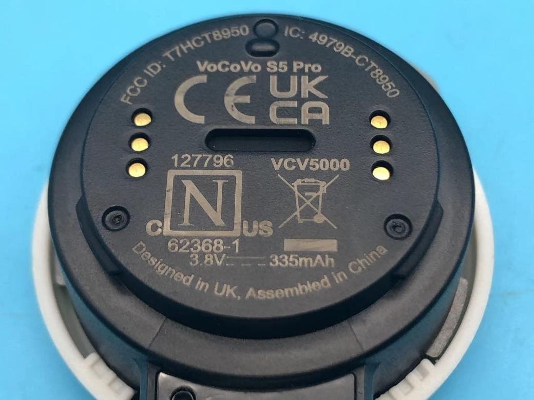
T7HCT8950
May 28, 2023DECT wireless Headset
Equipment Class
PUE - Part 15 Unlicensed PCS portable Tx held to ear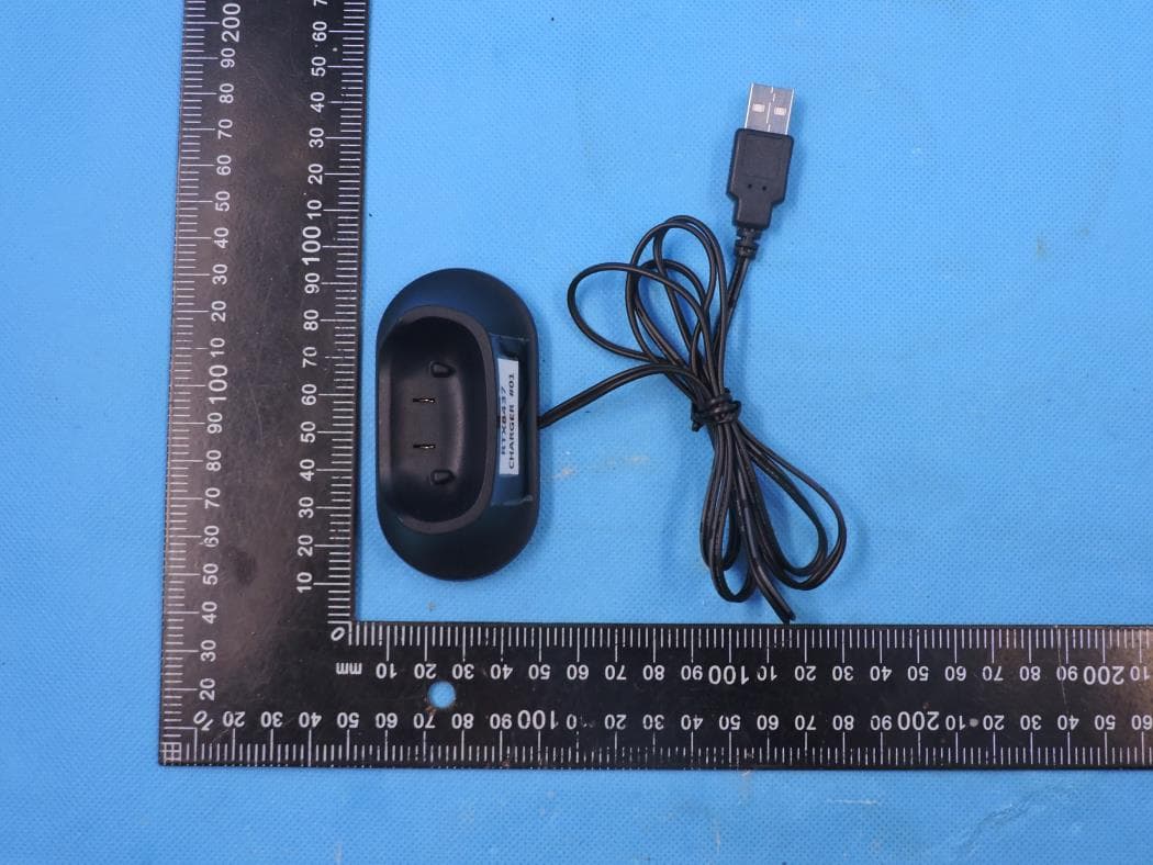
T7HCT8437
Mar 23, 2023Wireless Headset with DECT function
Equipment Class
PUE - Part 15 Unlicensed PCS portable Tx held to ear