T7HRTX4006UPCS Repeater
RTX Hong Kong Ltd.
Click to zoom
Application Details
- Equipment Class
- PUB - Part 15 Unlicensed PCS Base Station
- Date of Grant
- Feb 06, 2008
- Application Purpose
- Original Equipment
- Date of Application
- Feb 05, 2008
- Equipment Note
- UPCS Repeater
- Frequency Range
- 1921.53600000 - 1928.44800000
- Company
- RTX Hong Kong Ltd.
- Country
- Hong Kong
Documents & Files
Document Text
Text extracted from the exhibit documents filed with the FCC. Open a document above to read the original.
Users Manual
Contents 1) Getting to know your repeater...................... 2 Checking the package contents............................. 2 How it works......................................................... 2 Features............................................................ 3 Specifications................................................... 4 2) Setting up your repeater................................ 4 Setting up the base................................................ 5 Changing the telephone system PIN................ 5 Automatic registration.......................................... 5 Manual registrationError! Bookmark not defined. Registration for a daisy-chain layout................... 6 Registering to a different base.............................. 6 3) Installing the repeater.................................... 6 Finding the right location..................................... 6 Map the base's coverage area........................... 7 Test the location............................................... 7 Installing the repeater........................................... 8 Multiple-repeater systems..................................... 8 Incorrect installation........................................ 9 Correct installation........................................... 9 Daisy-chain installations................................ 10 4) Troubleshooting and Maintenance............. 11 Turning on the verification tone......................... 11 Maintenance....................................................... 12 5) Legal and warranty information................ 12 Important safety instructions.............................. 12 Important electrical considerations................ 13 FCC regulatory information............................... 13 Part 15 compliance......................................... 13 Privacy information....................................... 14 Radio interference information...................... 14 I.C. Notice........................................................... 15 Terminal Equipment...................................... 15 Radio Equipment........................................... 15 One Year Limited Warranty................................ 15 Contact Information............................................ 17 Having Trouble?............................................ 17 Need a Part?................................................... 17 Help for our Special Needs Customers.......... 17 1) Getting to know your repeater Checking the package contents You should have received the following items: • UDR100 DECT repeater • AC adapter • Mounting screw and wall anchor How it works The UDR100 repeater lets you extend the coverage area of your cordless DECT telephone system in all directions, including up and down. If the repeaters are installed so their coverage area overlaps the coverage area of the base, the base can hand-off calls to the repeaters as the user moves from one coverage area to another. When it's connected to the repeater, the mobile handset operates the exact same way as it does when connected to the base, and the hand-off from the base to the repeater can be completely invisible to the end user, even during an active call. Each base supports up to six repeaters, so you can extend coverage in all directions, including through floors and ceilings: In addition, the UDR100 supports a sequential or "daisy chain" layout to extend coverage in a single direction. Up to 3 repeaters can be installed in sequence: For detailed information on daisy-chain layout and configuration, contact your installer or refer to the UDR100 Administrator's Guide. Features • Automatic registration to the base • Up to 6 repeaters per base station • Up to 3 repeaters in a sequential or daisy-chain layout • 2 internal antennas to support 2 simultaneous calls • Repeater connection verification tone • Low power consumption Specifications AC power adapter: Input: 100 -240VAC 50 -60Hz Output; 5VDC 500mA Unit weight: 5oz (142g) Frequency band: 1920Mhz -1939Mhz Transmit power: 110mW Receiver sensitivity: <-92 dBm at 10-3 BER Operating Temperature 14° to 122° F (-10° to +50° C) Standards: Designed in accordance with the Digital Enhanced Cordless Telecommunications (DECT) standard Compliant with TBR6, TBR22 (Generic Access Profile, GAP), and ETS 300 700 - ETSI Wireless Relay Station Specification 2) Setting up your repeater Before installing the repeater, you need to activate the repeater mode on your base and then register the repeater to the base and any handsets. Before you start the registration process, be sure you have • A working base • A working handset registered to that base • Any repeaters you want to register to this base (you must complete the registration process separately for each repeater) • At least one of the AC adapters supplied with the repeaters. Use ONLY the power adapter that came with your repeater. A different power adapter may cause an electrical hazard or damage the repeater. Setting up the base Changing the telephone system PIN Before you start the registration process, you must reset the system PIN of your telephone to 0000 (consult the manual that came with your base for more information). After you reset the PIN, make sure to re-register the handset you used back to the base station. Automatic registration The repeater seeks out the base with strongest DECT/GAP signal and automatically registers to that base. Step 1: Make sure the repeater is powered off (i.e., the AC power adapter is not connected). Step 2: Set the base into registration mode. (Consult the owner's manual that came with your base station for more information. Step 3: Use the AC adapter to connect the repeater to a standard 120 V AC outlet. (Do not use a power outlet controlled by a wall switch.) The LED on the repeater flashes briefly, then remains on and steady. If the LED continues to flash, try registering the repeater again. The repeater is now registered to this base and is ready to use. You can safely d…
Text truncated - open the document above for the full version.
External Photos
FCC ID: T7HRTX4006 Project no.: 95524 Page 1 of 1 EXTERNAL PHOTOS – RTX 4002 DECT 6.0 WRS
ID Label/Location Info
MADE IN DENMARK UDR 100: ! Unit label Made in Denma rk UNIDEN TYPE: UDR 100 FCC ID: T7HRTX4006 IC: 4979B-RTX4006 S/N.: Use only power adapter provided UNIDEN TYPE: UDR 100 P/N.: 95100869 QTY: 1 FCC ID: T7HRTX4006 IC:4979B-RTX4006 Made in Denmark UNIDEN UDR100 P/N.: 95100869 CARTON NO.: OF QUANTITY: ORDER. No.: APPROVED BY: DATE: S/N.: I.T.E xxxx E305446 Giftbox label Outerbox label FCC Label Location
Internal Photos
FCC ID: T7HRTX4006 Project no.: 95524 Page 1 of 2 INTERNAL PHOTOS – RTX 4002 DECT 6.0 WRS Front view FCC ID: T7HRTX4006 Project no.: 95524 Page 2 of 2 Back view
RF Exposure Info
Prediction of MPE limit at a given distance Equation from page 18 of OET Bulletin 65, Edition 9 7-01 where: S = power density P = power input to the antennaG = power gain of the antenna in the direction of i nterest relative to an isotropic radiator R = distance to the center of radiation of the ante nna Valid for frequencies from 30 to 100.000 MHz Maximum peak output power at antenna input terminal : 20.10 (dBm) Maximum peak output power at antenna input terminal : 102.3292992 (mW) Antenna gain(typical): 3.30 (dBi) Maximum antenna gain: 2.13796209 (numeric) Prediction distance: 20 (cm) Prediction frequency: 1921.536 (MHz) MPE limit for uncontrolled exposure at prediction f requency: 1.00 (mW/cm^2) Power density at prediction frequency: 0.043524 (mW/cm^2) Maximum allowable antenna gain: 16.91 (dBi) Margin of Compliance: 13.61 (dB) 2 4 R PG S π =
Test Report
Nemko AS, Gaustadalléen 30, P.O.Box 73 Blindern, NO-0314 Oslo Norway T +47 22 96 03 30 F +47 22 96 05 50 Enterprise number NO974404532 Visiting address: Nemko Comlab, Gåsevikveien 8, P.O.Box 96, NO-2027 Kjeller Norway T +47 64 84 57 00 F +47 64 84 57 05 Test report no. : 95524-3 Item tested : RTX4006 DECT6.0 Type of equipment : UPCS Wireless Relay Station FCC ID : T7HRTX4006 Client : RTX Consumer Products Hong Kong Ltd. FCC Part 15, subpart D Isochronous UPCS Device 1920 - 1930 MHz Industry Canada RSS-213, Issue 2 2 GHz Licence-exempt Personal Communications Service Devices (LE-PCS) 7 February 2008 Authorized by : ......................... ..................... Egil Hauger Technical Verificator TEST REPORT FCC part 15D Project no.: 95524 FCC ID: T7HRTX4006 Nemko Comlab, N-2027 Kjeller Page 2 (56) CONTENTS 1 GENERAL INFORMATION ............................................................................................................... 3 1.1 Testhouse Info ................................................................................................................................... 3 1.2 Client Information............................................................................................................................... 3 1.3 Manufacturer (if other than client) ...................................................................................................... 3 2 TEST INFORMATION ....................................................................................................................... 4 2.1 Tested Item........................................................................................................................................ 4 2.2 Test Environment............................................................................................................................... 5 2.3 Test Period ........................................................................................................................................ 5 2.4 Test Engineer(s) ................................................................................................................................ 5 2.5 Test Equipment.................................................................................................................................. 5 2.6 Other Comments ............................................................................................................................... 5 3 TEST REPORT SUMMARY .............................................................................................................. 6 3.1 General .............................................................................................................................................. 6 3.2 Test Summary ................................................................................................................................... 7 4 TEST RESULTS................................................................................................................................ 8 4.1 Power Line Conducted Emissions ..................................................................................................... 8 4.2 Coordination with fixed microwave................................................................................................... 10 4.3 Digital Modulation Techniques......................................................................................................... 10 4.4 Labeling Requirements .................................................................................................................... 10 4.5 Antenna Requirement ...................................................................................................................... 11 4.6 Channel Frequencies....................................................................................................................... 11 4.7 Automatic Discontinuation of Transmission ..................................................................................... 12 4.8 Peak Power Output.......................................................................................................................... 13 4.9 Emission Bandwidth B..................................................................................................................... 21 4.10 Power Spectral Density.................................................................................................................... 24 4.11 In-Band Unwanted Emissions, Conducted....................................................................................... 27 4.12 Out-of-band Emissions, Conducted ................................................................................................. 29 4.13 Carrier Frequency Stability .............................................................................................................. 33 4.14 Frame Repetition Stability................................................................................................................ 34 4.15 Frame Period and Jitter ................................................................................................................... 34 4.16 Monitoring Threshold, Least Interfered Channel .............................................................................. 36 4.17 Threshold Monitoring Bandwidth ..................................................................................................... 38 4.18 Reaction Time and Monitoring Interval ............................................................................................ 39 4.19 Time and Spectrum Window Access Procedure .............................................................................. 41 4.20 Acknowledgements and Transmission Duration .............................................................................. 44 4.21 Dual Access Criteria Check .........................................................................................................…
Text truncated - open the document above for the full version.
Test Setup Photos
FCC ID: T7HRTX4006 Project no.: 95524 Page 1 of 1 PHOTOS OF TEST SET-UP – RTX 4002 DECT 6.0 WRS Antenna Gain Test Power line Conducted Emissions Test
Contact Information
Applicant
Erik Pedersen(Engineering Director)
Test Firm
Nemko ASFrode Sveinsen
Technical Specifications
| # | Rule Parts | Frequency Range | Power Output |
|---|---|---|---|
| 1 | 15D | 1.92 GHz - 1.93 GHz | 102.00 mW |
Other Applications from RTX Hong Kong Ltd.
T7HCT8930A
Aug 03, 2026DECT Wireless Headset
Equipment Class
PUE - Part 15 Unlicensed PCS portable Tx held to ear
T7HXB700
Jul 10, 2026Base EU
Equipment Class
PUB - Part 15 Unlicensed PCS Base Station
T7HCTH200
Jul 06, 2026Handset
Equipment Class
PUE - Part 15 Unlicensed PCS portable Tx held to ear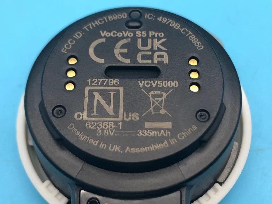
T7HCT8950
May 28, 2023DECT wireless Headset
Equipment Class
PUE - Part 15 Unlicensed PCS portable Tx held to ear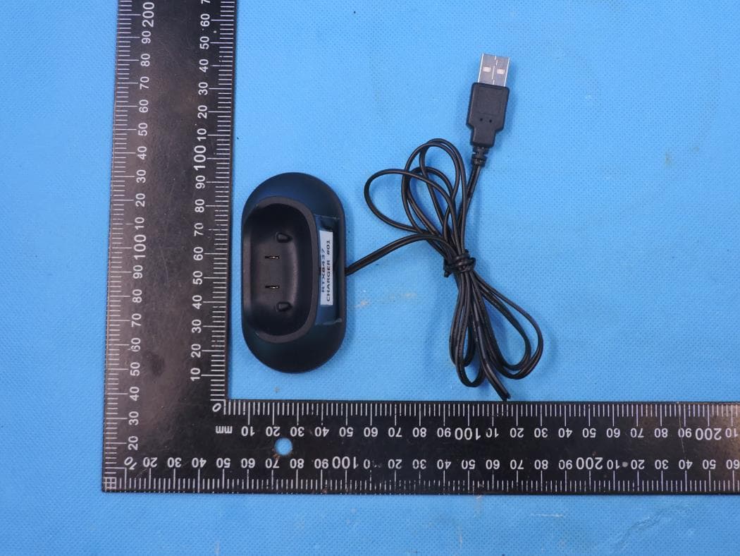
T7HCT8437
Mar 23, 2023Wireless Headset with DECT function
Equipment Class
PUE - Part 15 Unlicensed PCS portable Tx held to ear