T7HRTX8630DECT 6.0 Handset
RTX Hong Kong Ltd.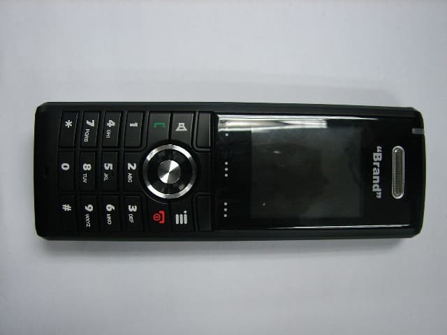
Click to zoom
Application Details
- Equipment Class
- PUE - Part 15 Unlicensed PCS portable Tx held to ear
- Date of Grant
- Apr 25, 2011
- Application Purpose
- Original Equipment
- Date of Application
- Apr 25, 2011
- Equipment Note
- DECT 6.0 Handset
- Frequency Range
- 1921.53600000 - 1928.44800000
- Company
- RTX Hong Kong Ltd.
- Country
- Hong Kong
Documents & Files
Document Text
Text extracted from the exhibit documents filed with the FCC. Open a document above to read the original.
Users Manual
Additional handset information RTX8630 Important safety information Charge the battery or handset only in combination with RTX8630 DECT Handset Desktop Charger and the Ten Pao S008CM0550060 or Phihong PSAC05R-055(RT)-R adapter that comes with the product. Plug the Ten Pao S008CM0550060 or Phihong PSAC05R-055(RT)-R AC/DC adaptor in a wall outlet socket near the equipment for easy access/removal of the AC/DC adaptor. Important battery information This product uses rechargeable Lithium-Ion batteries 3.7V, 1100mAh. Only use batteries that come with the handset or dedicated spare batteries marked with “Battery Pack, CE-MB206-5C-01 or BL-5C-Y01”. Do not use any other type, since this may present a risk of leakage, fire, explosion or other hazardous situation. For battery replacement or removal please remove the battery cover of the handset. Never disassemble, customize or short- circuit batteries. Do not place battery in fire or heat the battery. Charge battery only with RTX8630 Charger and the Ten Pao S008CM0550060 or Phihong PSAC05R-055(RT)-R adapter that comes with the product. Sensitive Electronic Environment Any radio-based equipment can potentially cause interference with other equipment and can be interfered from other equipment. This also applies for DECT equipment. However due to the very low transmission power level the chances for interference are very small. Research proves that operational DECT phones normally don’t influence electronic equipment however some precautions must be taken into account for sensitive electronic equipment e.g. sensitive laboratory equipment. When DECT phones operate in straight nearness of sensitive electronic equipment incidental influence can appear. You are advised not to place the DECT phone on or close (less than 10cm) to this kind of equipment, even in standby mode. Please also use the other documentation supplied with the various parts of your telephone system.Menulist Product disposal information For countries in the European Union The symbol depicted here has been affixed to your product in order to inform you that electrical and electronic products should not be disposed of as municipal waste. Electrical and electronic products including the cables, plugs and accessories should be disposed of separately in order to allow proper treatment, recovery and recycling. These products should be taken to a designated facility where the best available treatment, recovery and recycling techniques are available. Separate disposal has significant advantages: valuable materials can be re-used and it prevents the dispersion of unwanted substances into the municipal waste stream. This contributes to the protection of human health and the environment. Please be informed that a fine may be imposed for illegal disposal of electrical and electronic products via the general municipal waste stream. In order to facilitate separate disposal and environmentally sound recycling, arrangements have been made for local collection and recycling. In case your electrical and electronic products need to be disposed of please refer to your supplier or the contractual agreements that your company has made upon acquisition of these products. For countries outside the European Union Disposal of electrical and electronic products in countries outside the European Union should be done in line with the local regulations. If no arrangement has been made with your supplier, please contact the local authorities for further information. Battery disposal information Defect or exhausted batteries should never be disposed of as municipal waste. Return old batteries to the battery supplier, a licensed battery dealer or a designated collection facility. Do not incinerate batteries. Regulatory information Europe Declaration of conformity Česky “RTX Telecom” tímto prohlašuje, že tento “RTX806x/RTX808x” je ve shodě se základními požadavky a dalšími příslušnými ustanoveními směrnice 1999/5/ES. Dansk Undertegnede “RTX Telecom” erklærer herved, at følgende udstyr “RTX806x/RTX808x” overholder de væsentlige krav og øvrige relevante krav i direktiv 1999/5/EF. Deutsch Hiermit erklärt “RTX Telecom”, dass sich das Gerät “RTX806x/RTX808x” in Übereinstimmung mit den grundlegenden Anforderungen und den übrigen einschlägigen Bestimmungen der Richtlinie 1999/5/EG befindet. Eesti Käesolevaga kinnitab “RTX Telecom” seadme “RTX806x/RTX808x” vastavust direktiivi 1999/5/EÜ põhinõuetele ja nimetatud direktiivist tulenevatele teistele asjakohastele sätetele. English Hereby, “RTX Telecom”, declares that this “RTX806x/RTX808x” is in compliance with the essential requirements and other relevant provisions of Directive 1999/5/EC. Español Por medio de la presente “RTX Telecom” declara que el “RTX806x/RTX808x” cumple con los requisitos esenciales y cualesquiera otras disposiciones aplicables o exigibles de la Directiva 1999/5/CE. Ελληνική ΜΕ ΤΗΝ ΠΑΡΟΥΣΑ Η “RTX Telecom” ∆ΗΛΩΝΕΙ ΟΤΙ “RTX806x/RTX808x” ΣΥΜΜΟΡΦΩΝΕΤΑΙ ΠΡΟΣ ΤΙΣ ΟΥΣΙΩ∆ΕΙΣ ΑΠΑΙΤΗΣΕΙΣ ΚΑΙ ΤΙΣ ΛΟΙΠΕΣ ΣΧΕΤΙΚΕΣ ∆ΙΑΤΑΞΕΙΣ ΤΗΣ Ο∆ΗΓΙΑΣ 1999/5/ΕΚ. Français Par la présente “RTX Telecom” déclare que l’appareil “RTX806x/RTX808x” est conforme aux exigences essentielles et aux autres dispositions pertinentes de la directive 1999/5/CE. Íslenska Hér með lýsir “RTX Telecom” yfir því að “RTX806x/RTX808x” er í samræmi við grunnkröfur og aðrar kröfur, sem gerðar eru í tilskipun 1999/5/EC. Italiano Con la presente “RTX Telecom” dichiara che questo “RTX806x/RTX808x” è conforme ai requisiti essenziali ed alle altre disposizioni pertinenti stabilite dalla direttiva 1999/5/CE. Latviski Ar šo “RTX Telecom” deklarē, ka “RTX806x/RTX808x” atbilst Direktīvas 1999/5/EK būtiskajām prasībām un citiem ar to saistītajiem noteikumiem. Lietuvių Šiuo “RTX Telecom” deklaruoja, kad šis “RTX806x/RTX808x” atitinka esminius reikalavimus ir kitas 1999/5/EB Direktyvos nuostatas. Malti Hawnhekk, “RTX Telecom”, jiddikjara li dan “RTX806x/RTX808x” jik konforma mal-ħtiġijiet essenzjali u ma provvedimenti oħrajn…
Text truncated - open the document above for the full version.
Users Manual
SME VoIP System Guide, Version 1.5 Proprietary and Confidential Chapter: About This Document 1 SME VoIP System Guide Installation & Configuration Network Deployment Operation & Management Technical Reference Document Version 1.5 © Dec-2010 RTX Telecom A/S, Denmark SME VoIP System Guide, Version 1.5 Proprietary and Confidential Chapter: About This Docum ent 2 Trademarks RTX and the combinations of its logo thereof are trademarks of RTX Telecom A/S, Denmark. Other product names used in this publication are for identification purposes and maybe the trademarks of their respective companies. Disclaimer The contents of this document are provided in connection with RTX products. RTX makes no representations with respect to completeness or accuracy of the contents of this publication and reserves the right to make changes to product descriptions, usage, etc., at any time without notice. No license, whether express, implied, to any intellectual property rights are granted by this publication Confidentiality This document should be regarded as confidential, unauthorized copying is not allowed © Dec-2010 RTX Telecom A/S, Denmark, All rights reserved http://www.rtx.dk SME VoIP System Guide, Version 1.5 Proprietary and Confidential Chapter: About This Document 3 Contents SME VoIP System Guide .................................................................................................................................... 1 Contents ............................................................................................................................................................ 3 1 About This Document ................................................................................................................................ 8 1.1 Audience .................................................................................................................................................. 8 1.2 When Should I Read This Guide .............................................................................................................. 8 1.3 Important Assumptions ........................................................................................................................... 8 1.4 What’s Inside This Guide ......................................................................................................................... 8 1.5 What’s Not in This guide.......................................................................................................................... 9 1.6 Abbreviations ......................................................................................................................................... 10 1.7 References/Related Documentation ..................................................................................................... 10 1.8 Document History .................................................................................................................................. 10 1.9 Documentation Feedback ..................................................................................................................... 10 2 Introduction – System Overview ............................................................................................................. 11 2.1 Hardware Setup ..................................................................................................................................... 11 2.2 Components of SME VoIP System ......................................................................................................... 12 2.2.1 RTX Base Stations ........................................................................................................................ 12 2.2.2 SME VoIP Administration Server/Software ................................................................................. 12 2.2.3 RTX Wireless Handset .................................................................................................................. 13 2.3 Wireless Bands ...................................................................................................................................... 13 2.4 System Capacity (in Summary) .............................................................................................................. 13 2.5 Advantages of SME VoIP System ........................................................................................................... 14 3 SME System Deployment Scenarios ........................................................................................................ 15 3.1 Multi-cell System ................................................................................................................................... 15 3.2 Multi-cell Setup ..................................................................................................................................... 15 3.3 Case Studies ........................................................................................................................................... 16 3.3.1 Case ##1: Isolated Buildings ........................................................................................................ 16 3.3.2 Case ##2: Location with co-located partners .............................................................................. 17 3.3.3 Case ##3: Large to Medium Sized Enterprises ............................................................................ 18 3.3.4 Case ##4: Large Enterprises at Different Locations ..................................................................... 18 4 SME VoIP Network Planning/Optimization ............................................................................................. 20 4.1 Network Requirements ......................................................................................................................... 20 4.2 Deployment Considerations ....................................................................................…
Text truncated - open the document above for the full version.
Attestation Statements
RTX Products Hong Kong Ltd. 11/F., CAC Tower, 165 Hoi Bun Road, Kwun Tong, Kowloon, Hong Kong Tel : +852 2487 3718 Fax : +852 2480 6121 Web : www.rtx.hk E-mail : [email protected] RTX Telecom A/S: Stroemmen 6, DK-9400 Nørresundby Tel : +45 9632 2300 Fax : +45 9632 2310 Press Release For immediate release Announcement of Corporate Name Change Hong Kong, September 09, 2008 - We are delighted to announce that RTX Consumer Products Hong Kong Limited which is headed by Mr. Peter Christensen, the Vice President of RTX Telecom A/S, has changed its corporate name to RTX Products Hong Kong Limited effective September 09, 2008. The change of the English name does not affect the Chinese name of the Company, which will remain unchanged as “愛創域香港有限公司”. The Board considers the new name of the Company provides a better identification of the Company’s development, which signifies towards the ever-present goal of delivering innovative quality products for the professional business market. The change of the company name will not affect any of the business with our existing customers and the board believes it is in the interest of the Company and its Shareholders as a whole. For accounting purpose, please take note that all payments should be made according to our invoice instructions and all transactions in regarding to RTX Consumer Products Hong Kong Limited will change to RTX Products Hong Kong Limited. About RTX Telecom A/S RTX Telecom is an internationally operating group which develops, produces and sells products, equipment and technological solutions within wireless communication and other telecom products. With headquarters located in Noerresundby, Denmark, RTX Telecom A/S is a listed company in the Copenhagen stock exchange since year 2000. About RTX Products Hong Kong Limited With base of operations in Hong Kong, RTX Products comprises development, production and sale of wireless products to OEMs and professional business market. The product range covers corded telephones, cordless telephones, and other wireless communication products. The RTX Products business unit is headed by Vice President Peter Christensen. RTX Products Hong Kong Limited Peter Christensen Vice President RTX Products Hong Kong Ltd. 11/F., CAC Tower, 165 Hoi Bun Road, Kwun Tong, Kowloon, Hong Kong Tel : +852 2487 3718 Fax : +852 2480 6121 Web : www.rtx.hk E-mail : [email protected] RTX Telecom A/S: Stroemmen 6, DK-9400 Nørresundby Tel : +45 9632 2300 Fax : +45 9632 2310 Press Contact: Fanny Wai, Marketing Manager Phone: +852 2487 3718 E-mail: [email protected] http://www.rtx.dk
RF Exposure Info
DAT-P-152/98-01 SAR_Report_Nemko_6620_840_FCC_CalData_RTX8630 Appendix for the Report Dosimetric Assessment of the Portable Device RTX 8630 (FCC ID: T7HRTX8630) (IC ID: 4979B-RTX8630) According to the FCC Requirements Calibration Data March 30, 2011 IMST GmbH Carl-Friedrich-Gauß-Str. 2 D-47475 Kamp-Lintfort Customer RTX Products Hong Kong Ltd. 11/F, CAC Tower, 165 Hoi Bun Road Kwun Tong, Kowloon Hong Kong Dasy_Report_FCC_DECT_1900_1.1.doc/22.05.2006/CH DAT-P-152/98-01 Cal_D1900V2_SN5d051_0909 Page 1 of 8 _ Calibration_Certificate_Dipole_V1.0/01.08.2009/ABo Calibration Certificate Certificate No: Cal_D1900V2_SN5d051_0909 Object: D1900V2 SN: 5d051 Date of Calibration: September 09, 2009 Next Calibration: September 2011 Object Condition: In Tolerance Calibration Equipment used: Test Equipment Serial Number Last calibration Calibrated by Next calibration Powermeter E4416A GB41050414 Dec 08 Agilent Techn. (ISO/IEC 17025, 1-1784162174-1) Dec 10 Power Sensor E9301H US40010212 Dec 08 Agilent Techn. (ISO/IEC 17025, 1-1784041195-1) Dec 10 Powermeter E4417A GB41050441 Dec 08 Agilent Techn. (ISO/IEC 17025, 1-1674038198-1) Dec 10 Power Sensor E9301A MY41495584 Dec 08 Agilent Techn. (ISO/IEC 17025, 1-1784041307-1) Dec 10 Network Analyzer E5071C MY46103220 Aug 09 Rohde& Schwarz (14967-DKD-00201- 2009-08) Aug 10 Reference Probe ET3DV6 SN 1669 Feb 09 SPEAG, No ET3- 1669_Feb09 Feb 10 DAE3 SN 335 Feb 09 SPEAG, No DAE3- 335_Feb09 Feb 10 Cal_D1900V2_SN5d051_0909 Page 2 of 8 Calibration is performed according the following standards: IEEE 1528-2003 "IEEE Recommended Practice for Determining the Peak Spatial - Averaged Specific Absorption Rate (SAR) in the Human Head from Wireless Communication Devices: Measurement Technique", December 2003 IEC 62209-1 "Procedure to measure the Specific Absorption Rate (SAR) for hand - held devices used in close proximity to the ear (frequency range of 300 MHz to 3GHz)", February 2005 Federal Communications Commission Office of Engineering & Technologies (FCCOET) "Evaluating Compliance wit FCC Guidelines for Human Exposure to Radiofrequency Electromagnetic Fields; Additional Information for Evaluating Compliance of Mobile and Portable Devices with FCC Limits for Human Exposure to Radiofrequency Emissions", Supplement C (Edition 01-01) to Bulletin 65 Additional Documentation: DASY 4 System Handbook prepared by: reviewed by: Alexander Rahn André van den Bosch test engineer quality assurance engineer 08/ABo Cal_D1900V2_SN5d051_0909 Page 3 of 8 Measurement Conditions DASY Version: Dasy 4; V4.7 Phantom: SAM Phantom 1340 Distance Dipole Center – TSL: 10mm With spacer Zoom Scan res. dx, dy, dz = 5mm Frequency: 1900 MHz ± 1MHz Head TSL Parameters Temperature Permittivity Conductivity Nominal Head TSL Parameters 22.0 40.0 1.40 Measured Head TSL Parameters 22.0 40.3 ± 6% 1.45 S/m ± 6% SAR result with Head TSL Averaged over 1g SAR measured 250mW input power 9.10 mW/g SAR normalized normalized to 1W 36.40 mW/g SAR for nominal Head TSL parameters normalized to 1W 35.90 mW/g ± 16.5 % (k=2) Averaged over 10g SAR measured 250mW input power 4.76 mW/g SAR normalized normalized to 1W 19.04 mW/g SAR for nominal Head TSL parameters normalized to 1W 18.96 mW/g ± 16.5 % (k=2) Cal_D1900V2_SN5d051_0909 Page 4 of 8 Body TSL Parameters Temperature Permittivity Conductivity Nominal Body TSL Parameters 22.0 53.30 1.52 Measured Body TSL Parameters 22.0 52.90 ± 6% 1.54 S/m ± 6% SAR result with Body TSL Averaged over 1g SAR measured 250mW input power 9.42 mW/g SAR normalized normalized to 1W 37.68 mW/g SAR for nominal Body TSL parameters normalized to 1W 37.28 mW/g ± 16.5 % (k=2) Averaged over 10g SAR measured 250mW input power 4.97 mW/ g SAR normalized normalized to 1W 19.88 mW/g SAR for nominal Body TSL parameters normalized to 1W 19.77 mW/g ± 16.5 % (k=2) General Antenna Parmeters Antenna Parameters with Head TSL Impedance, transformed to feed point 48.2 jΩ - 1.3 jΩ Return Loss -33.0 dB Antenna Parameter with Body TSL Impedance, transformed to feed point 53.9 jΩ - 0.4 jΩ Return Loss -28.3 dB After long term use with 100W radiated power, only a slight warming of the dipole near the feedpoint can be measured. The dipole is made of standard semigrid coaxial cable. The center conductor of the feeding line is directly connected to the second arm of the dipole. The antenna is therefore short-circuited for DC signals. Additional EUT Data Manufactured by: SPEAG Manufactured on: January 15, 1998 Cal_D1900V2_SN5d051_0909 Page 5 of 8 SAR result with Head TSL Test Laboratory: IMST GmbH, DASY Blue (I); File Name: 090909_b_1669.da4 DUT: Dipole 1900 MHz SN: 5d051; Type: D1900V2; Serial: D1900V2 - SN5d051 Program Name: System Performance Check at 1900 MHz Communication System: CW; Frequency: 1900 MHz;Duty Cycle: 1:1 Medium parameters used: f = 1900 MHz; σ = 1.45 mho/m; ε r = 40.3; ρ = 1000 kg/m 3 Phantom section: Flat Section DASY4 Configuration: - Probe: ET3DV6R - SN1669; ConvF(5.11, 5.11, 5.11); Calibrated: 10.02.2009 - Sensor-Surface: 4mm (Mechanical Surface Detection) - Electronics: DAE3 Sn335; Calibrated: 09.02.2009 - Phantom: SAM Glycol 1176; Type: Speag; Serial: 1176 - Measurement SW: DASY4, V4.7 Build 80; Postprocessing SW: SEMCAD, V1.8 Build 186 d=10mm, Pin=250mW/Area Scan (7x7x1): Measurement grid: dx=10mm, dy=10mm Maximum value of SAR (measured) = 10.4 mW/g d=10mm, Pin=250mW/Zoom Scan (7x7x7)/Cube 0: Measurement grid: dx=5mm, dy=5mm, dz=5mm Reference Value = 91.3 V/m; Power Drift = -0.152 dB Peak SAR (extrapolated) = 15.9 W/kg SAR(1 g) = 9.1 mW/g; SAR(10 g) = 4.76 mW/g Maximum value of SAR (measured) = 10.3 mW/g Cal_D1900V2_SN5d051_0909 Page 6 of 8 SAR result with Body TSL Test Laboratory: IMST GmbH, DASY Blue (I); File Name: 090909_b_1669.da4 DUT: Dipole 1900 MHz SN: 5d051; Type: D1900V2; Serial: D1900V2 - SN5d051 Program Name: System Performance Check at 1900 MHz Communication System: CW; Frequency: 1900 MHz;Duty Cycle: 1:1 Medium parameters used: f = 1900 MHz; σ = 1.54 mho/m; ε r = 52.9; ρ = 1000 kg/m 3 Pha…
Text truncated - open the document above for the full version.
RF Exposure Info
DAT-P-152/98-01 SAR_Report_Nemko_6620_840_FCC_DECT_Plots_RTX8630 Page 1 of 16 Appendix for the Report Dosimetric Assessment of the Portable Device 8630 (FCC ID: T7HRTX8630) (IC ID: 4979B-RTX8630) According to the FCC Requirements SAR Distribution Plots March 30, 2011 IMST GmbH Carl-Friedrich-Gauß-Str. 2 D-47475 Kamp-Lintfort Customer RTX Products Hong Kong Ltd. 11/F, CAC Tower, 165 Hoi Bun Road Kwun Tong, Kowloon Hong Kong The test results only relate to the items tested. This report shall not be reproduced except in full without the written approval of the testing laboratory. Dasy_Report_FCC_DECT_1900_1.1.doc/22.05.2006/CH SAR_Report_Nemko_6620_840_FCC_DECT_Plots_RTX8630 Page 2 of 16 dasy_report_fcc_DECT_1900_plots_1.0.doc/110.05.2006/ABo Table of Contents 1 SAR DISTRIBUTION PLOTS, HEAD MEASUREMENTS, ANTENNA 1 ................................................ 3 2 SAR DISTRIBUTION PLOTS, HEAD MEASUREMENTS, ANTENNA 2 ................................................ 7 3 SAR DISTRIBUTION PLOTS, BODY MEASUREMENTS, ANTENNA 1 ............................................. 11 4 SAR DISTRIBUTION PLOTS, BODY MEASUREMENTS, ANTENNA 2 ............................................. 13 5 SAR Z-AXIS SCANS (VALIDATION) ......................................................................................................... 15 6 SAR Z-AXIS SCANS (MEASUREMENTS) ................................................................................................ 16 SAR_Report_Nemko_6620_840_FCC_DECT_Plots_RTX8630 Page 3 of 16 dasy_report_fcc_DECT_1900_plots_1.0.doc/110.05.2006/ABo 1 SAR Distribution Plots, Head Measurements, Antenna 1 Test Laboratory: Imst GmbH, DASY Yellow (II); File Name: RTX8630_yplm_1_ant1.da4 DUT: RTX; Type: 8630; Program Name: DECT Communication System: DECT US; Frequency: 1924.99 MHz;Duty Cycle: 1:24 Medium parameters used: f = 1924.99 MHz; σ = 1.46 mho/m; ε r = 39.7; ρ = 1000 kg/m 3 Phantom section: Left Section DASY4 Configuration: - Probe: EX3DV4 - SN3536; ConvF(7.77, 7.77, 7.77); Calibrated: 16.09.2010 - Sensor-Surface: 4mm (Mechanical Surface Detection) - Electronics: DAE4 Sn631; Calibrated: 17.09.2010 - Phantom: SAM Glycol 1340; Type: QD 000 P40 CB; Serial: TP-1340 - Measurement SW: DASY4, V4.7 Build 80; Postprocessing SW: SEMCAD, V1.8 Build 186 Cheek Left/Area Scan (8x14x1): Measurement grid: dx=15mm, dy=15mm Maximum value of SAR (measured) = 0.017 mW/g Cheek Left/Zoom Scan (7x7x7)/Cube 0: Measurement grid: dx=5mm, dy=5mm, dz=5mm Reference Value = 3.08 V/m; Power Drift = 0.144 dB Peak SAR (extrapolated) = 0.033 W/kg SAR(1 g) = 0.020 mW/g; SAR(10 g) = 0.012 mW/g Maximum value of SAR (measured) = 0.021 mW/g Fig. 1: SAR distribution for DECT US, antenna 1, channel 2, cheek position, left side of head (March 29, 2011; Ambient Temperature: 21.2°C; Liquid Temperature: 20.7°C). SAR_Report_Nemko_6620_840_FCC_DECT_Plots_RTX8630 Page 4 of 16 dasy_report_fcc_DECT_1900_plots_1.0.doc/110.05.2006/ABo Test Laboratory: Imst GmbH, DASY Yellow (II); File Name: RTX8630_yplm_2_ant1.da4 DUT: RTX; Type: 8630; Program Name: DECT Communication System: DECT US; Frequency: 1924.99 MHz;Duty Cycle: 1:24 Medium parameters used: f = 1924.99 MHz; σ = 1.46 mho/m; ε r = 39.7; ρ = 1000 kg/m 3 Phantom section: Left Section DASY4 Configuration: - Probe: EX3DV4 - SN3536; ConvF(7.77, 7.77, 7.77); Calibrated: 16.09.2010 - Sensor-Surface: 4mm (Mechanical Surface Detection) - Electronics: DAE4 Sn631; Calibrated: 17.09.2010 - Phantom: SAM Glycol 1340; Type: QD 000 P40 CB; Serial: TP-1340 - Measurement SW: DASY4, V4.7 Build 80; Postprocessing SW: SEMCAD, V1.8 Build 186 Tilted Left/Area Scan (8x14x1): Measurement grid: dx=15mm, dy=15mm Maximum value of SAR (measured) = 0.012 mW/g Tilted Left/Zoom Scan (7x7x7)/Cube 0: Measurement grid: dx=5mm, dy=5mm, dz=5mm Reference Value = 2.78 V/m; Power Drift = -0.173 dB Peak SAR (extrapolated) = 0.023 W/kg SAR(1 g) = 0.012 mW/g; SAR(10 g) = 0.00553 mW/g Maximum value of SAR (measured) = 0.014 mW/g Fig. 2: SAR distribution for DECT US, antenna 1, channel 2, tilted position, left side of head (March 29, 2011; Ambient Temperature: 21.2°C; Liquid Temperature: 20.7°C). SAR_Report_Nemko_6620_840_FCC_DECT_Plots_RTX8630 Page 5 of 16 dasy_report_fcc_DECT_1900_plots_1.0.doc/110.05.2006/ABo Test Laboratory: Imst GmbH, DASY Yellow (II); File Name: RTX8630_yprm_1_ant1.da4 DUT: RTX; Type: 8630; Program Name: DECT Communication System: DECT US; Frequency: 1924.99 MHz;Duty Cycle: 1:24 Medium parameters used: f = 1924.99 MHz; σ = 1.46 mho/m; ε r = 39.7; ρ = 1000 kg/m 3 Phantom section: Right Section DASY4 Configuration: - Probe: EX3DV4 - SN3536; ConvF(7.77, 7.77, 7.77); Calibrated: 16.09.2010 - Sensor-Surface: 4mm (Mechanical Surface Detection) - Electronics: DAE4 Sn631; Calibrated: 17.09.2010 - Phantom: SAM Glycol 1340; Type: QD 000 P40 CB; Serial: TP-1340 - Measurement SW: DASY4, V4.7 Build 80; Postprocessing SW: SEMCAD, V1.8 Build 186 Cheek Right/Area Scan (8x14x1): Measurement grid: dx=15mm, dy=15mm Maximum value of SAR (measured) = 0.022 mW/g Cheek Right/Zoom Scan (7x7x7)/Cube 0: Measurement grid: dx=5mm, dy=5mm, dz=5mm Reference Value = 2.82 V/m; Power Drift = 0.101 dB Peak SAR (extrapolated) = 0.035 W/kg SAR(1 g) = 0.022 mW/g; SAR(10 g) = 0.012 mW/g Maximum value of SAR (measured) = 0.024 mW/g Fig. 3: SAR distribution for DECT US, antenna 1, channel 2, cheek position, right side of head (March 29, 2011; Ambient Temperature: 21.2°C; Liquid Temperature: 20.7°C). SAR_Report_Nemko_6620_840_FCC_DECT_Plots_RTX8630 Page 6 of 16 dasy_report_fcc_DECT_1900_plots_1.0.doc/110.05.2006/ABo Test Laboratory: Imst GmbH, DASY Yellow (II); File Name: RTX8630_yprm_2_ant1.da4 DUT: RTX; Type: 8630; Program Name: DECT Communication System: DECT US; Frequency: 1924.99 MHz;Duty Cycle: 1:24 Medium parameters used: f = 1924.99 MHz; σ = 1.46 mho/m; ε r = 39.7; ρ = 1000 kg/m 3 Phantom section: Right Section DASY4 Configuration: - Probe: EX3DV4 - SN3536; ConvF(7.77, 7.77, 7.77); Calibrated: 16.09.2010 - Sensor-Surface: 4mm (Mec…
Text truncated - open the document above for the full version.
RF Exposure Info
DAT-P-152/98-01 SAR_Report_Nemko_6620_840_FCC_DECT_RTX8630 Page 1 of 32 Report Dosimetric Assessment of the Portable Device 8630 (FCC ID: T7HRTX8630) (IC ID: 4979B-RTX8630) According to the FCC Requirements March 30, 2011 IMST GmbH Carl-Friedrich-Gauß-Str. 2 D-47475 Kamp-Lintfort Customer RTX Products Hong Kong Ltd. 11/F, CAC Tower, 165 Hoi Bun Road Kwun Tong, Kowloon Hong Kong The test results only relate to the items tested. This report shall not be reproduced except in full without the written approval of the testing laboratory. SAR_Report_Nemko_6620_840_FCC_DECT_RTX8630 Page 2 of 32 Dasy_Report_FCC_DECT_1900_1.3.doc/10.09.2010/ABo Executive Summary The 8630 is a new cordless phone (Portable Device) from RTX operating in the 1920 MHz frequency range (US DECT Standard). The device has two integrated antennas which are working as a diversity system. The objective of the measurements done by IMST was the dosimetric assessment of one 8630 device. The handset was set in a test mode during the measurements, which allowed separate settings of frequency and antenna configuration. The examinations have been carried out with the dosimetric assessment system „DASY4“. The measurements were conducted according to the Supplement C to OET Bulletin 65 of the Federal Communications Commission (FCC) Guidelines [OET 65] for evaluating compliance of mobile and portable devices with FCC limits for human exposure (general population) to radiofrequency emissions. All measurements have been performed in accordance to the recommendations given by SPEAG. Compliance Statement The RTX 8630 cordless telephone (FCC ID: T7HRTX8630) is in compliance with the Federal Communications Commission (FCC) Guidelines [OET 65] for uncontrolled exposure. The phone was tested in addition to the head positions in the following body worn configurations: with headset connected (display towards the phantom, distance 0 mm) with headset connected (display towards the ground, distance 0 mm) Maximum SAR 1g = 0.041 W/kg (Cheek right side of the head, Antenna 1, Channel 2) prepared by: ........................................ reviewed by: ..................................... Alexander Rahn Dr. -Ing. Ch. Bornkessel test engineer quality assurance engineer SAR_Report_Nemko_6620_840_FCC_DECT_RTX8630 Page 3 of 32 Dasy_Report_FCC_DECT_1900_1.3.doc/10.09.2010/ABo Table of Contents 1 SUBJECT OF INVESTIGATION .................................................................................................................... 4 2 THE IEEE STANDARD C95.1-1999 AND THE FCC EXPOSURE CRITERIA ....................................... 4 2.1 DISTINCTION BETWEEN EXPOSED POPULATION, DURATION OF EXPOSURE AND FREQUENCIES ........... 4 2.2 DISTINCTION BETWEEN MAXIMUM PERMISSIBLE EXPOSURE AND SAR LIMITS ....................................... 5 2.3 SAR LIMIT .................................................................................................................................................. 5 3 THE FCC MEASUREMENT PROCEDURE ................................................................................................. 6 3.1 GENERAL REQUIREMENTS......................................................................................................................... 6 3.2 DEVICE OPERATING NEXT TO A PERSON’S EAR ....................................................................................... 6 4 B…
Text truncated - open the document above for the full version.
Contact Information
Applicant
Erik Pedersen(Engineering Director)
Technical Contact
RTX Products Hong Kong Ltd.Soren Bove
[email protected]45 9632 2300
RTX Telecom A/S, Strommen 6, DK-9400 Norresundby · Denmark
Non-Technical Contact
RTX Products Hong Kong Ltd.Kenny Chan
[email protected]852 2487 3718
Test Firm
Nemko ASFrode Sveinsen
Technical Specifications
| # | Rule Parts | Frequency Range | Power Output |
|---|---|---|---|
| 1 | 15D | 1.92 GHz - 1.93 GHz | 105.00 mW |
Other Applications from RTX Hong Kong Ltd.
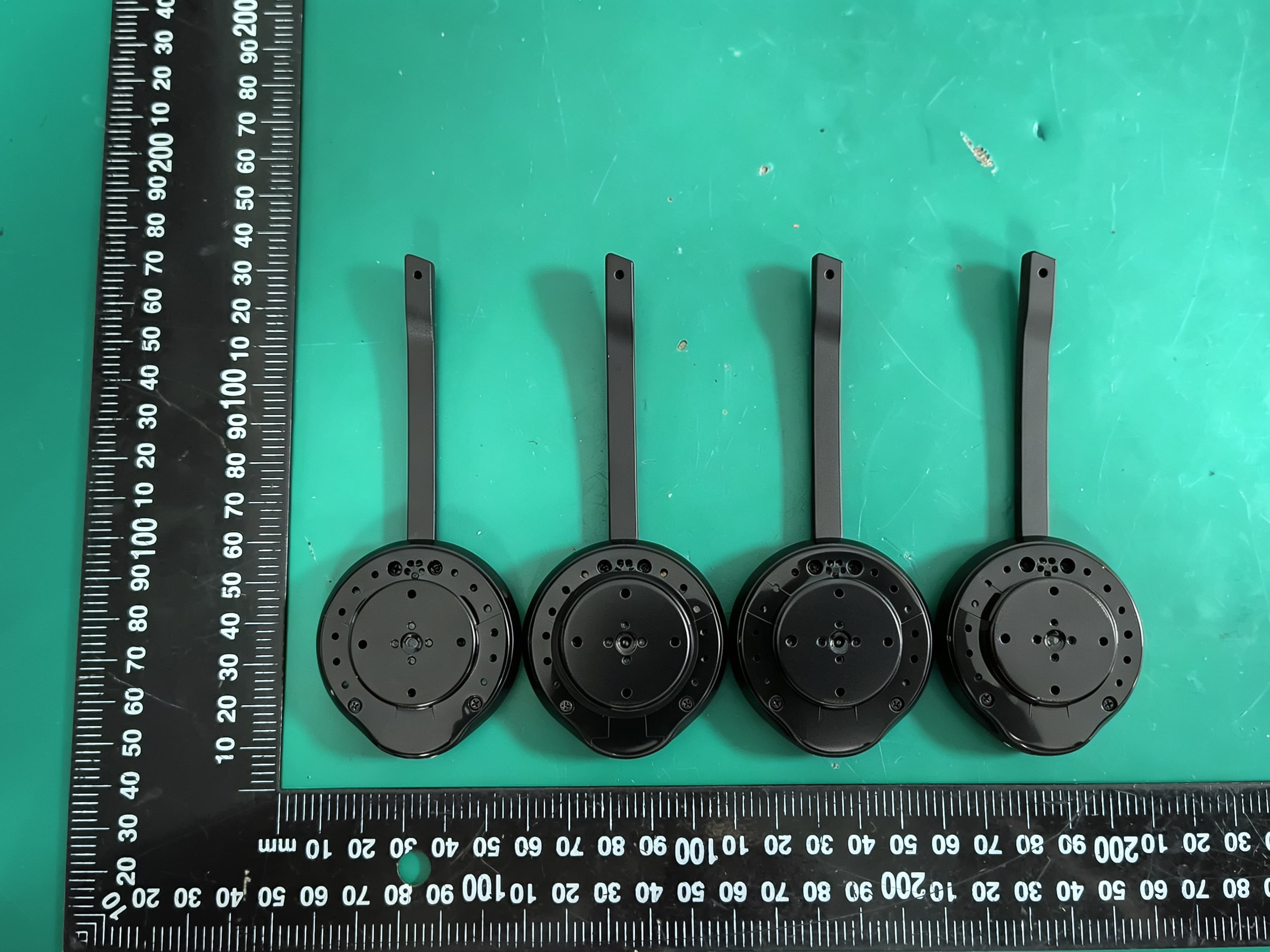
T7HCT8930A
Aug 03, 2026DECT Wireless Headset
Equipment Class
PUE - Part 15 Unlicensed PCS portable Tx held to ear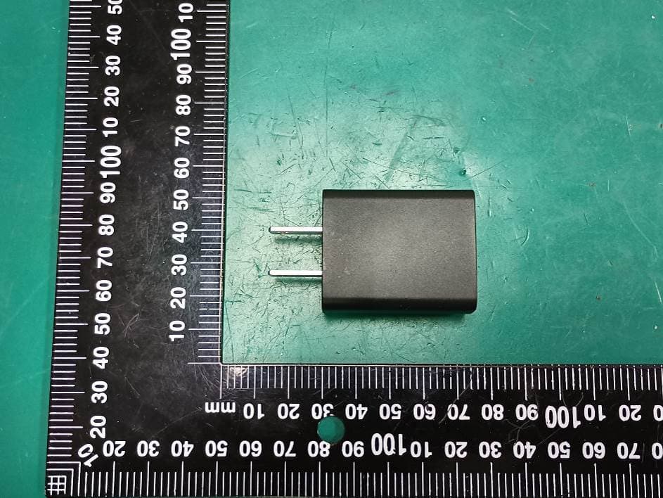
T7HXB700
Jul 10, 2026Base EU
Equipment Class
PUB - Part 15 Unlicensed PCS Base Station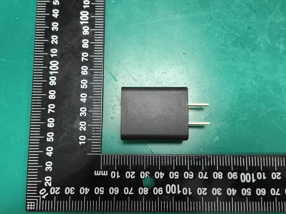
T7HCTH200
Jul 06, 2026Handset
Equipment Class
PUE - Part 15 Unlicensed PCS portable Tx held to ear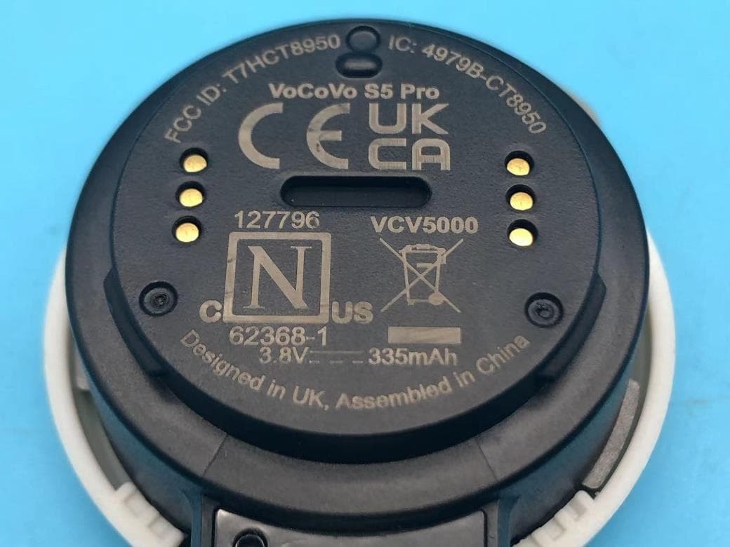
T7HCT8950
May 28, 2023DECT wireless Headset
Equipment Class
PUE - Part 15 Unlicensed PCS portable Tx held to ear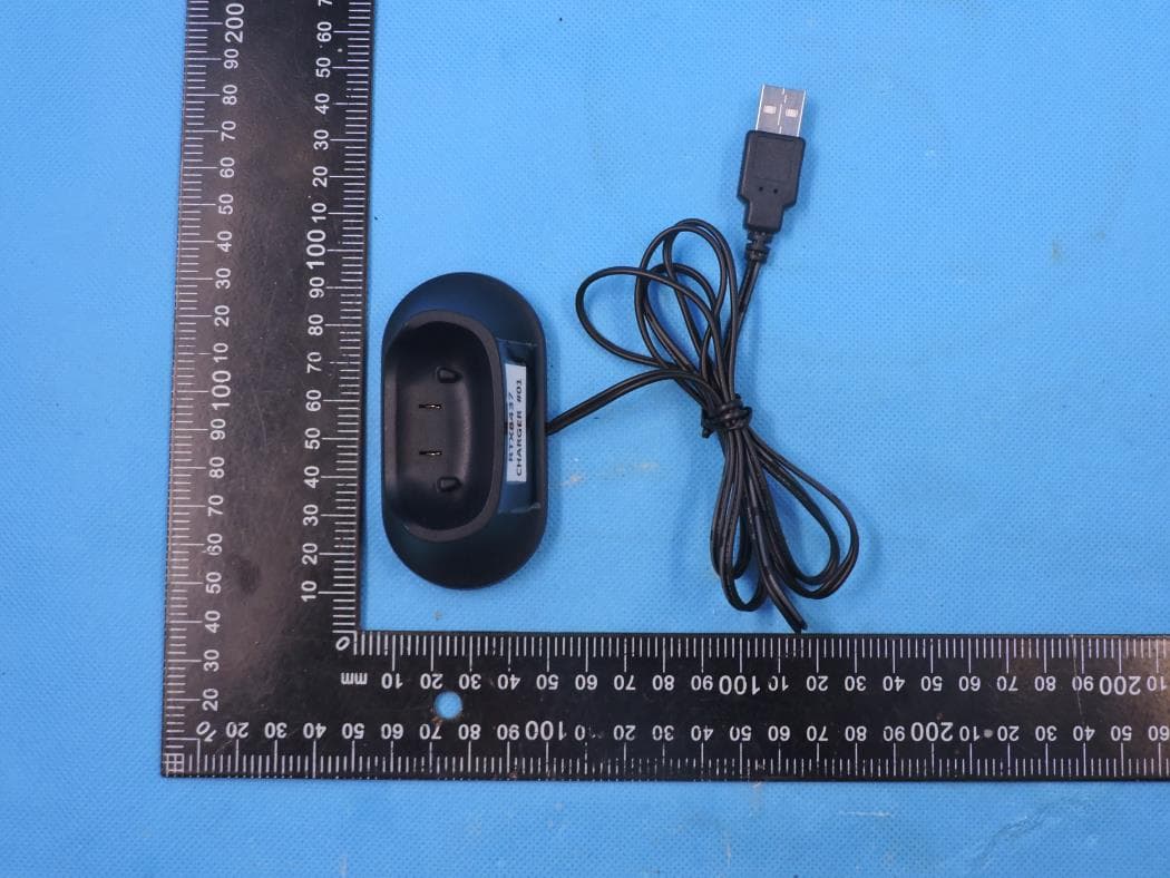
T7HCT8437
Mar 23, 2023Wireless Headset with DECT function
Equipment Class
PUE - Part 15 Unlicensed PCS portable Tx held to ear