T7HWMTAV30-01Cordless Telephone Handset
RTX Hong Kong Ltd.
Click to zoom
Application Details
- Equipment Class
- PUE - Part 15 Unlicensed PCS portable Tx held to ear
- Date of Grant
- Sep 10, 2007
- Application Purpose
- Original Equipment
- Date of Application
- Sep 09, 2007
- Equipment Note
- Cordless Telephone Handset
- Frequency Range
- 1921.53600000 - 1928.44800000
- Company
- RTX Hong Kong Ltd.
- Country
- Hong Kong
Documents & Files
Document Text
Text extracted from the exhibit documents filed with the FCC. Open a document above to read the original.
Users Manual
150mm 130mm P0611005-CT7381-HS-IM02 31-07-2007 RTX Consumer Products Hong Kong Limited Quick Start Guide WESTELL HANDSET &CHARGER R5 DEL OK INT LOG PC 1 2 3 4 5 6 7 8 9 0 * P # R G H I GHI A B C ABC D E F DEF J K L JKL MNO P ORS PORS T U V TUV W XYZ WXYZ A99-WMTA3030-01 ( for US countries )A99-WMTA3060-01 ( for EU countries ) EN GETTING STARTED 1. Inserting rechargeable batteries into handsetOnthe handset,gently pull offthe batterycover and insert the rechargeable batteries which come with the package. MAKINGSURE BATTERIESFOLLOWTHEPOLARITYINDICATIONMARKED INSIDEBATTERYCOMPARTMENT.Replace batterycover onto handset. LCD screen will turn up. Pressthe redbutton as soon as batteryis installed. OFF 2. Connecting powerOn the charger unit connect the power adaptor to the AC power outlet. 4. IMPORTANT - Charge the battery for 5 hours before first useBefore using the handset, it is strongly recommended to charge the handset for at least 5 hours before first usage. For future use, whenever thehandset shows a low battery indication, please place the handset into the charging cradle. 3. Place the handset in the charging cradleThe charging LED will light up if the handset is correctly. placed Safety Instructions For Batteries1. Use only the battery in the handset of your cordless phone.2. Do not dispose of the battery in a fire as it may explode. Check with local codes for possible special instructions.3. Do not open or mutilate the battery. Released elect rolyte is corrosive and may cause damage to the eyes and skin. It may be toxic if swallowed.4. Exercise care in handling batteries in order not to short the battery with conducting materials such as rings, bracelets and keys. The battery or5. Charge the battery (ies) provided with or identified for use with this product only in accordance with the instructions and limitations specified i n 6. Observe proper polarity orientation between the battery pack and the battery charger. For Handset Unit: 3 X 1.2V AAA size NiMH Rechargeable BatteryBrand name: Lexel Battery (Shenzhen) Co. Ltd.Type No: LH060-3AH45conduction material may overheat and cause burns.this manual. 5. Registration:The Handset must be registered to the base unit prior to first use. Prior to registering handset, please turn on Base Screen unit. The chargerunit is not the base unit.1. An unregistered handset display shows "Press OK to register".2. Presses "OK". A 30-second timer is set on handset for registration.3. "Select" (press) the Register Key on Base Screen unit.4. Selects (presses once) the Register softkey on the LCD. A 30-second timer is set on base for registration.5. Handset registers with base.6. Handset display indicates that registration is completed, and solicits a handset name.7. Use keypad to type name of handset. When complete press "OK". 6. Handset is now ready to use with base unit.The handset can be powered ON and OFF by pressing and holding for 5 seconds the red OFF button. The LCD screen and button back lightwill illuminate when on. The button back lights will remain ON for 10 seconds after the release of any button pressing and then will turn off. DEL OK INT LOG PC 1 2 3 4 5 6 7 8 9 0 * P # R G H I GHI A B C ABC D E F DEF J K L JKL MNO P ORS PORS T U V TUV W XYZ WXYZ FR Notice de securite concernant les piles 1. 1.2.3.4.5.6. 2.3. 4.5.6. / Information sur la reglementation US C I.T.E.
External Photos
FCC ID: T7HWMTAV30-01 IC ID: 4979B-WMTAV3001 Project no.: 88370 Page 1 of 2 EXTERNAL PHOTOS – Westell Handset Westell UPCS Handset FCC ID: T7HWMTAV30-01 IC ID: 4979B-WMTAV3001 Project no.: 88370 Page 2 of 2 PHOTOS OF ACCESSORIES Charger with cradle
ID Label/Location Info
RTX America Inc. Ref. : kl Doc. : Label placement_HS_A90- WMTAV3030-01.doc Date : 20-aug-2007 Page : 1 of 1 page(s) Label placement for DECT 6.0 Cordless Handset. Handset label for model: A90-WMTAV3030-01 Country of origin: China The label is to be placed on the handset in the battery compartment under the batteries. (See picture below) The handset will be sold without the batteries installed in the battery compartment. P0611005B-CT7381-HS-US-LB01 P0611005-CT7381-HS-US-LB01SIZE:26 (W) x32 (H) mmCOLOR:Black text on silver backgroundBARCODE FORMAT:CODE 128 TABLE B FORMAT 2:1 IMPORTANT! Above information shows relative size and boldness only. Adjustment may be required at time of production by factories due to incline surface. 10-08-2007 H/S Label (US) RTX consumer products Hong Kong Limited AA - current year (eg. "07" for year 2007 CC - current month (eg. "06" for June) DDDDDD - progressive number Remark: RS,XX,YY - fixed letters FCC ID : T7HWMTAV30-01IC : 4979B-WMTAV3001 CAUTION RISK OF DAMAGE TOTHE PHONE MAYOCCUR IF BATTERYIS REPLACED BY ANINCORRECT TYPE. DISPOSE OF USEDBATTERY PROPERLY. ASSEMBLED IN CHINA IPEI barcode FOR BATTERIES SEE USER INSTRUCTION H/S + CHARGER: A99-WMTAV3030-01 US C S/N No : AARSCCDDDDDD HANDSET: A90-WMTAV3030-01 I.T.E. FCC ID : T7HWMTAV30-01IC : 4979B-WMTAV3001 CAUTION RISK OF DAMAGE TOTHE PHONE MAYOCCUR IF BATTERYIS REPLACED BY ANINCORRECT TYPE. DISPOSE OF USEDBATTERY PROPERLY. ASSEMBLED IN CHINA IPEI barcode FOR BATTERIES SEE USER INSTRUCTION H/S + CHARGER: A99-WMTAV3030-01 US C S/N No : AARSCCDDDDDD HANDSET: A90-WMTAV3030-01 I.T.E.
Internal Photos
FCC ID: T7HWMTAV30-01 IC ID: 4979B-WMTAV3001 Project no.: 88370 Page 1 of 2 INTERNAL PHOTOS – Westell Handset Westell UPCS Handset FCC ID: T7HWMTAV30-01 IC ID: 4979B-WMTAV3001 Project no.: 88370 Page 2 of 2 Without Shielding
RF Exposure Info
DAT-P-152/98-01 SAR_Report_Nemko_6620_650_FCC_CalData_Westell_1 dasy_report_fcc_850_1900_cal_data_2.0.doc/08.01.2005/CH Appendix for the Report Dosimetric Assessment of the Westell A90-WMTAV3030-01 (FCC ID: T7HWMTAV30-01) According to the FCC Requirements Calibration Data August 14, 2007 IMST GmbH Carl-Friedrich-Gauß-Str. 2 D-47475 Kamp-Lintfort Customer RTX Consumer Products Hong Kong Ltd. 11/F, CAC Tower, Hoi Bun Road Kwun Tong, Kowloon Hong Kong This report shall not be reproduced except in full without the written approval of the testing laboratory.
RF Exposure Info
DAT-P-152/98-01 SAR_Report_Nemko_6620_650_FCC_DECT_SAR Plots_Westell_1 Page 1 of 10 Appendix for the Report Dosimetric Assessment of the Westell A90-WMTAV3030-01 (FCC ID: T7HWMTAV30-01) According to the FCC Requirements SAR Distribution Plots August 14, 2007 IMST GmbH Carl-Friedrich-Gauß-Str. 2 D-47475 Kamp-Lintfort Customer RTX Consumer Products Hong Kong Ltd. 11/F, CAC Tower, Hoi Bun Road Kwun Tong, Kowloon Hong Kong The test results only relate to the items tested. This report shall not be reproduced except in full without the written approval of the testing laboratory. dasy_report_fcc_DECT_1900_plots_1.0.doc/110.05.2006/ABo SAR_Report_Nemko_6620_650_FCC_DECT_SAR Plots_Westell_1 Page 2 of 10 dasy_report_fcc_DECT_1900_plots_1.0.doc/110.05.2006/ABo Table of Contents 1 SAR DISTRIBUTION PLOTS, HEAD MEASUREMENTS......................................................................... 3 2 SAR DISTRIBUTION PLOTS, BODY MEASUREMENTS........................................................................ 7 3 SAR Z-AXIS SCANS (VALIDATION)........................................................................................................... 9 4 SAR Z-AXIS SCANS (MEASUREMENTS)................................................................................................ 10 SAR_Report_Nemko_6620_650_FCC_DECT_SAR Plots_Westell_1 Page 3 of 10 dasy_report_fcc_DECT_1900_plots_1.0.doc/110.05.2006/ABo 1 SAR Distribution Plots, Head Measurements Test Laboratory: Imst GmbH, DASY Yellow (II); File Name: Winona_yplm_1.da4 DUT: Winona; Type: Westell; Program Name: Cheek Left Communication System: DECT US, Single Slot; Frequency: 1924.99 MHz;Duty Cycle: 1:24 Medium parameters used: f = 1924.99 MHz; σ = 1.46 mho/m; ε r = 41; ρ = 1000 kg/m 3 Phantom section: Left Section DASY4 Configuration: - Probe: ET3DV6R - SN1669; ConvF(4.93, 4.93, 4.93); Calibrated: 15.02.2007 - Sensor-Surface: 4mm (Mechanical Surface Detection) - Electronics: DAE3 Sn335; Calibrated: 09.02.2007 - Phantom: SAM Glycol 1340; Type: QD 000 P40 CB; Serial: TP-1340 - Measurement SW: DASY4, V4.7 Build 53; Postprocessing SW: SEMCAD, V1.8 Build 172 Cheek Left/Area Scan (7x14x1): Measurement grid: dx=15mm, dy=15mm Maximum value of SAR (measured) = 0.019 mW/g Cheek Left/Zoom Scan (7x7x7)/Cube 0: Measurement grid: dx=5mm, dy=5mm, dz=5mm Reference Value = 2.53 V/m; Power Drift = 0.132 dB Peak SAR (extrapolated) = 0.028 W/kg SAR(1 g) = 0.018 mW/g; SAR(10 g) = 0.010 mW/g Maximum value of SAR (measured) = 0.020 mW/g Fig. 1: SAR distribution for DECT US, channel 2, cheek position, left side of head (June 22, 2007; Ambient Temperature: 22.2°C; Liquid Temperature: 21.1°C). SAR_Report_Nemko_6620_650_FCC_DECT_SAR Plots_Westell_1 Page 4 of 10 dasy_report_fcc_DECT_1900_plots_1.0.doc/110.05.2006/ABo Test Laboratory: Imst GmbH, DASY Yellow (II); File Name: Winona_yplm_2.da4 DUT: Winona; Type: Westell; Program Name: Tilted Left Communication System: DECT US, Single Slot; Frequency: 1924.99 MHz;Duty Cycle: 1:24 Medium parameters used: f = 1924.99 MHz; σ = 1.46 mho/m; ε r = 41; ρ = 1000 kg/m 3 Phantom section: Left Section DASY4 Configuration: - Probe: ET3DV6R - SN1669; ConvF(4.93, 4.93, 4.93); Calibrated: 15.02.2007 - Sensor-Surface: 4mm (Mechanical Surface Detection) - Electronics: DAE3 Sn335; Calibrated: 09.02.2007 - Phantom: SAM Glycol 1340; Type: QD 000 P40 CB; Serial: TP-1340 - Measurement SW: DASY4, V4.7 Build 53; Postprocessing SW: SEMCAD, V1.8 Build 172 Tilted Left/Area Scan (7x14x1): Measurement grid: dx=15mm, dy=15mm Maximum value of SAR (measured) = 0.008 mW/g Tilted Left/Zoom Scan (7x7x7)/Cube 0: Measurement grid: dx=5mm, dy=5mm, dz=5mm Reference Value = 2.44 V/m; Power Drift = 0.059 dB Peak SAR (extrapolated) = 0.013 W/kg SAR(1 g) = 0.0081 mW/g; SAR(10 g) = 0.0046 mW/g Maximum value of SAR (measured) = 0.009 mW/g Fig. 2: SAR distribution for DECT US, channel 2, tilted position, left side of head (June 22, 2007; Ambient Temperature: 22.2°C; Liquid Temperature: 21.1°C). SAR_Report_Nemko_6620_650_FCC_DECT_SAR Plots_Westell_1 Page 5 of 10 dasy_report_fcc_DECT_1900_plots_1.0.doc/110.05.2006/ABo Test Laboratory: Imst GmbH, DASY Yellow (II); File Name: Winona_yprm_1.da4 DUT: Winona; Type: Westell; Program Name: Cheek Right Communication System: DECT US, Single Slot; Frequency: 1924.99 MHz;Duty Cycle: 1:24 Medium parameters used: f = 1924.99 MHz; σ = 1.46 mho/m; ε r = 41; ρ = 1000 kg/m 3 Phantom section: Right Section DASY4 Configuration: - Probe: ET3DV6R - SN1669; ConvF(4.93, 4.93, 4.93); Calibrated: 15.02.2007 - Sensor-Surface: 4mm (Mechanical Surface Detection) - Electronics: DAE3 Sn335; Calibrated: 09.02.2007 - Phantom: SAM Glycol 1340; Type: QD 000 P40 CB; Serial: TP-1340 - Measurement SW: DASY4, V4.7 Build 53; Postprocessing SW: SEMCAD, V1.8 Build 172 Cheek Right/Area Scan (7x14x1): Measurement grid: dx=15mm, dy=15mm Maximum value of SAR (measured) = 0.015 mW/g Cheek Right/Zoom Scan (7x7x7)/Cube 0: Measurement grid: dx=5mm, dy=5mm, dz=5mm Reference Value = 2.19 V/m; Power Drift = 0.162 dB Peak SAR (extrapolated) = 0.023 W/kg SAR(1 g) = 0.015 mW/g; SAR(10 g) = 0.0083 mW/g Maximum value of SAR (measured) = 0.016 mW/g Fig. 3: SAR distribution for DECT US, channel 2, cheek position, right side of head (June 22, 2007; Ambient Temperature: 22.2°C; Liquid Temperature: 21.1°C). SAR_Report_Nemko_6620_650_FCC_DECT_SAR Plots_Westell_1 Page 6 of 10 dasy_report_fcc_DECT_1900_plots_1.0.doc/110.05.2006/ABo Test Laboratory: Imst GmbH, DASY Yellow (II); File Name: Winona_yprm_2.da4 DUT: Winona; Type: Westell; Program Name: Tilted Right Communication System: DECT US, Single Slot; Frequency: 1924.99 MHz;Duty Cycle: 1:24 Medium parameters used: f = 1924.99 MHz; σ = 1.46 mho/m; ε r = 41; ρ = 1000 kg/m 3 Phantom section: Right Section DASY4 Configuration: - Probe: ET3DV6R - SN1669; ConvF(4.93, 4.93, 4.93); Calibrated: 15.02.2007 - Sensor-Surface: 4mm (Mechanical Surface Detection) - Electronics: DAE3 Sn335; Calibrated: 09.02.2007 - Phantom: SAM Glycol 1340; Type: QD 000 P40…
Text truncated - open the document above for the full version.
RF Exposure Info
DAT-P-152/98-01 SAR_Report_Nemko_6620_650_FCC_DECT_1900_Westell Page 1 of 32 Report Dosimetric Assessment of the Portable Device Westell A90-WMTAV3030-01 (FCC ID: T7HWMTAV30-01) According to the FCC Requirements August 14, 2007 IMST GmbH Carl-Friedrich-Gauß-Str. 2 D-47475 Kamp-Lintfort Customer RTX Consumer Products Hong Kong Ltd. 11/F, CAC Tower, Hoi Bun Road Kwung Tong, Kwoloon Hong Kong The test results only relate to the items tested. This report shall not be reproduced except in full without the written approval of the testing laboratory. Dasy_Report_FCC_DECT_1900_1.1.doc/22.05.2006/CH SAR_Report_Nemko_6620_650_FCC_DECT_1900_Westell Page 2 of 32 Dasy_Report_FCC_DECT_1900_1.1.doc/22.05.2006/CH Executive Summary The A90-WMTAV3030-01 is a cordless telephone (Portable Device) from Westell operating in the 1920 MHz frequency range (US DECT Standard). The device has an integrated antenna. The objective of the measurements done by IMST was the dosimetric assessment of one device in the 1920 MHz frequency range. The handset was set to use one specific frequency during the measurements. The examinations have been carried out with the dosimetric assessment system „DASY4“. The measurements were made according to the Supplement C to OET Bulletin 65 of the Federal Communications Commission (FCC) Guidelines [OET 65] for evaluating compliance of mobile and portable devices with FCC limits for human exposure (general population) to radiofrequency emissions. All measurements have been performed in accordance to the recommendations given by SPEAG. The Westell A90-WMTAV3030-01 cordless telephone (FCC ID: T7HWMTAV30-01) is in compliance with the Federal Communications Commission (FCC) Guidelines [OET 65] for uncontrolled exposure. The phone was tested in addition to the head positions in the following configurations: Body worn with the following accessory: • with belt clip, without headset, (display towards the ground, distance 0 mm) • with belt clip and headset (display towards the ground, distance 0 mm) prepared by: ........................................... reviewed by: ..................................... Alexander Rahn Dipl.-Ing. Chritoph Hennes test engineer quality assurance engineer IMST GmbH Carl-Friedrich-Gauß-Straße 2 D-47475 Kamp-Lintfort Tel. +49- 2842-981 373 Fax +49- 2842-981 399 email: [email protected] SAR_Report_Nemko_6620_650_FCC_DECT_1900_Westell Page 3 of 32 Dasy_Report_FCC_DECT_1900_1.1.doc/22.05.2006/CH Table of Contents 1 SUBJECT OF INVESTIGATION.................................................................................................................... 4 2 THE IEEE STANDARD C95.1-1999 AND THE FCC EXPOSURE CRITERIA....................................... 4 2.1 DISTINCTION BETWEEN EXPOSED POPULATION, DURATION OF EXPOSURE AND FREQUENCIES........... 4 2.2 DISTINCTION BETWEEN MAXIMUM PERMISSIBLE EXPOSURE AND SAR LIMITS....................................... 5 2.3 SAR LIMIT.................................................................................................................................................. 5 3 THE FCC MEASUREMENT PROCEDURE................................................................................................. 6 3.1 GENERAL REQUIREMENTS......................................................................................................................... 6 3.2 DEVICE OPERATING NEXT TO A PERSON’S EAR....................................................................................... 6 4 BODY-WORN CONFIGURATIONS.............................................................................................................. 9 4.1 POC (PTT) POSITION............................................................................................................................. 10 4.2 PHANTOM REQUIREMENTS...................................................................................................................... 10 4.3 TEST TO BE PERFORMED......................................................................................................................... 10 5 THE MEASUREMENT SYSTEM................................................................................................................. 10 5.1 PHANTOM................................................................................................................................................. 12 5.2 PROBE...................................................................................................................................................... 12 5.3 MEASUREMENT PROCEDURE.................................................................................................................. 13 5.4 UNCERTAINTY ASSESSMENT................................................................................................................... 14 6 SAR RESULTS............................................................................................................................................... 15 7 EVALUATION................................................................................................................................................. 16 8 APPENDIX....................................................................................................................................................... 17 8.1 ADMINISTRATIVE DATA............................................................................................................................ 17 8.2 DEVICE UNDER TEST AND TEST CONDITIONS......................................................................................... 17 8.3 TISSUE RECIPES...................................................................................................................................... 17 8.4 MATERIAL PARAMETERS......................................................................................................................... 18 8.5 SIMPLIFIED PERFORMANCE CHECKING.........................................................…
Text truncated - open the document above for the full version.
Test Report
Nemko AS, Gaustadalléen 30, P.O.Box 73 Blindern, NO-0314 Oslo Norway T +47 22 96 03 30 F +47 22 96 05 50 Enterprise number NO974404532 Visiting address: Nemko Comlab, Gåsevikveien 8, P.O.Box 96, NO-2027 Kjeller Norway T +47 64 84 57 00 F +47 64 84 57 05 Test report no. : 88370-8 Item tested : A90-WMTAV3030-01 Type of equipment : UPCS Handset FCC ID : T7HWMTAV30-01 Client : RTX Consumer Products Hong Kong Ltd. FCC Part 15, subpart D Isochronous UPCS Device 1920 - 1930 MHz 10 September 2007 Authorized by : ............................ .................. Egil Hauger Technical Verificator TEST REPORT FCC part 15D Project no.: 88370 FCC ID: T7HWMTAV30-01 Nemko Comlab, N-2027 Kjeller Page 2 (51) CONTENTS 1 GENERAL INFORMATION ............................................................................................................... 3 1.1 Testhouse Info ................................................................................................................................... 3 1.2 Client Information............................................................................................................................... 3 1.3 Manufacturer (if other than client) ...................................................................................................... 3 2 TEST INFORMATION ....................................................................................................................... 4 2.1 Tested Item........................................................................................................................................ 4 2.2 Test Environment............................................................................................................................... 5 2.3 Test Period ........................................................................................................................................ 5 2.4 Test Engineers................................................................................................................................... 5 2.5 Test Equipment.................................................................................................................................. 5 2.6 Other Comments ............................................................................................................................... 5 3 TEST REPORT SUMMARY .............................................................................................................. 6 3.1 General .............................................................................................................................................. 6 3.2 Test Summary ................................................................................................................................... 7 4 TEST RESULTS................................................................................................................................ 8 4.1 Power Line Conducted Emissions ..................................................................................................... 8 4.2 Coordination with fixed microwave................................................................................................... 11 4.3 Digital Modulation Techniques......................................................................................................... 11 4.4 Labeling Requirements .................................................................................................................... 11 4.5 Antenna Requirement ...................................................................................................................... 12 4.6 Channel Frequencies....................................................................................................................... 12 4.7 Automatic Discontinuation of Transmission ..................................................................................... 13 4.8 Peak Power Output.......................................................................................................................... 14 4.9 Emission Bandwidth B..................................................................................................................... 17 4.10 Power Spectral Density.................................................................................................................... 19 4.11 In-Band Unwanted Emissions, Conducted....................................................................................... 22 4.12 Out-of-band Emissions, Conducted ................................................................................................. 24 4.13 Carrier Frequency Stability .............................................................................................................. 32 4.14 Frame Repetition Stability................................................................................................................ 33 4.15 Frame Period and Jitter ................................................................................................................... 33 4.16 Monitoring Threshold, Least Interfered Channel .............................................................................. 35 4.17 Threshold Monitoring Bandwidth ..................................................................................................... 37 4.18 Reaction Time and Monitoring Interval ............................................................................................ 38 4.19 Time and Spectrum Window Access Procedure .............................................................................. 40 4.20 Acknowledgements and Transmission Duration .............................................................................. 41 4.21 Dual Access Criteria Check ............................................................................................................. 43 4.22 Alternative Monitoring Interval ................................................................…
Text truncated - open the document above for the full version.
Test Setup Photos
FCC ID: T7HWMTAV30-01 IC ID: 4979B-WMTAV3001 Project no.: 88370 Page 1 of 2 TEST SET-UP PHOTOS – Westell Handset Radiated Output Power Test FCC ID: T7HWMTAV30-01 IC ID: 4979B-WMTAV3001 Project no.: 88370 Page 2 of 2 Power-line Conducted Emissions Test
Contact Information
Applicant
Erik Pedersen(Engineering Director)
Test Firm
Nemko ASFrode Sveinsen
Technical Specifications
| # | Rule Parts | Frequency Range | Power Output |
|---|---|---|---|
| 1 | 15D | 1.92 GHz - 1.93 GHz | 120.00 mW |
Other Applications from RTX Hong Kong Ltd.
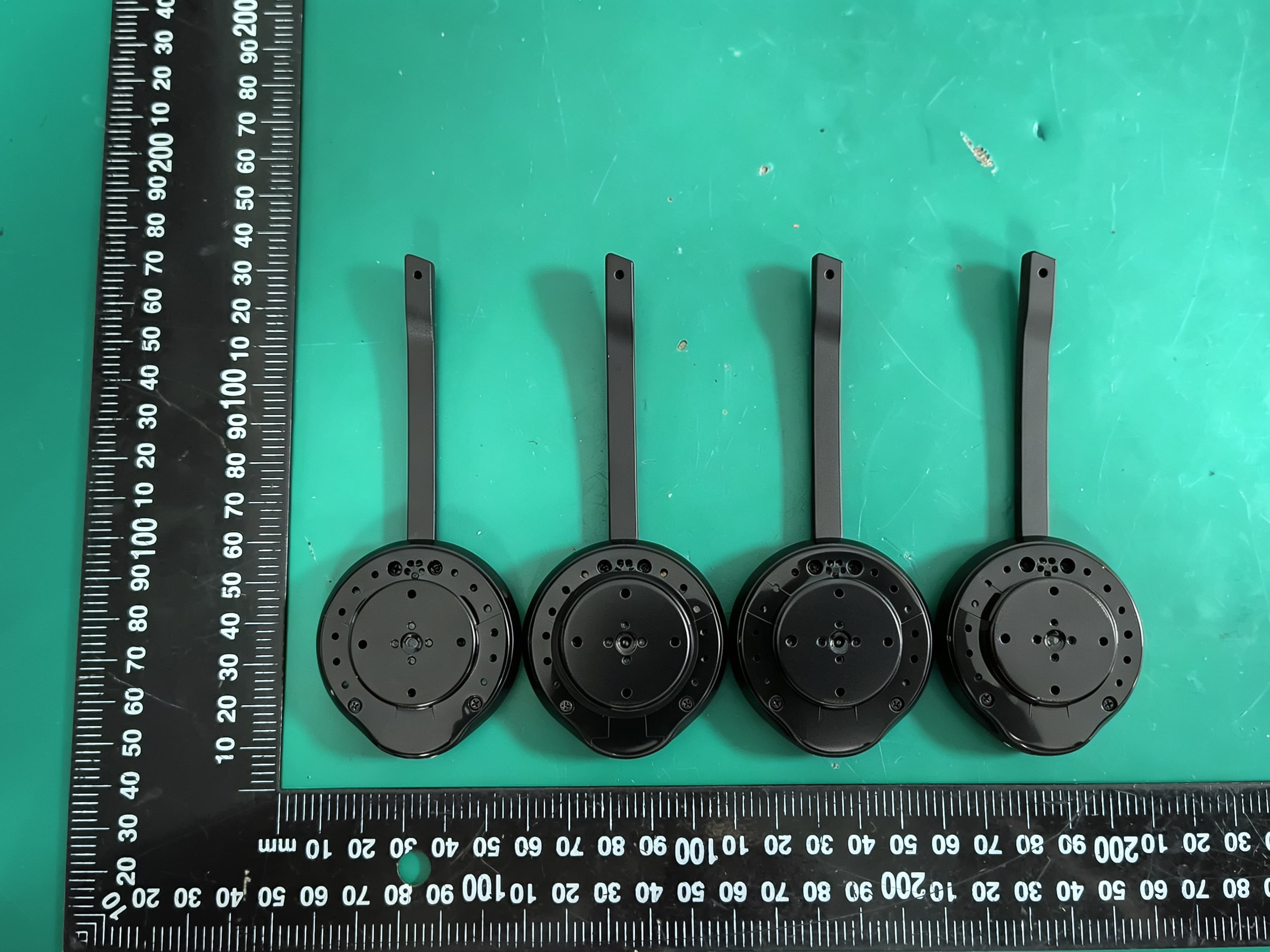
T7HCT8930A
Aug 03, 2026DECT Wireless Headset
Equipment Class
PUE - Part 15 Unlicensed PCS portable Tx held to ear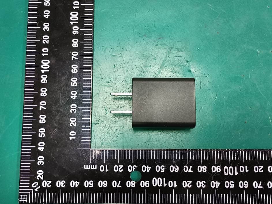
T7HXB700
Jul 10, 2026Base EU
Equipment Class
PUB - Part 15 Unlicensed PCS Base Station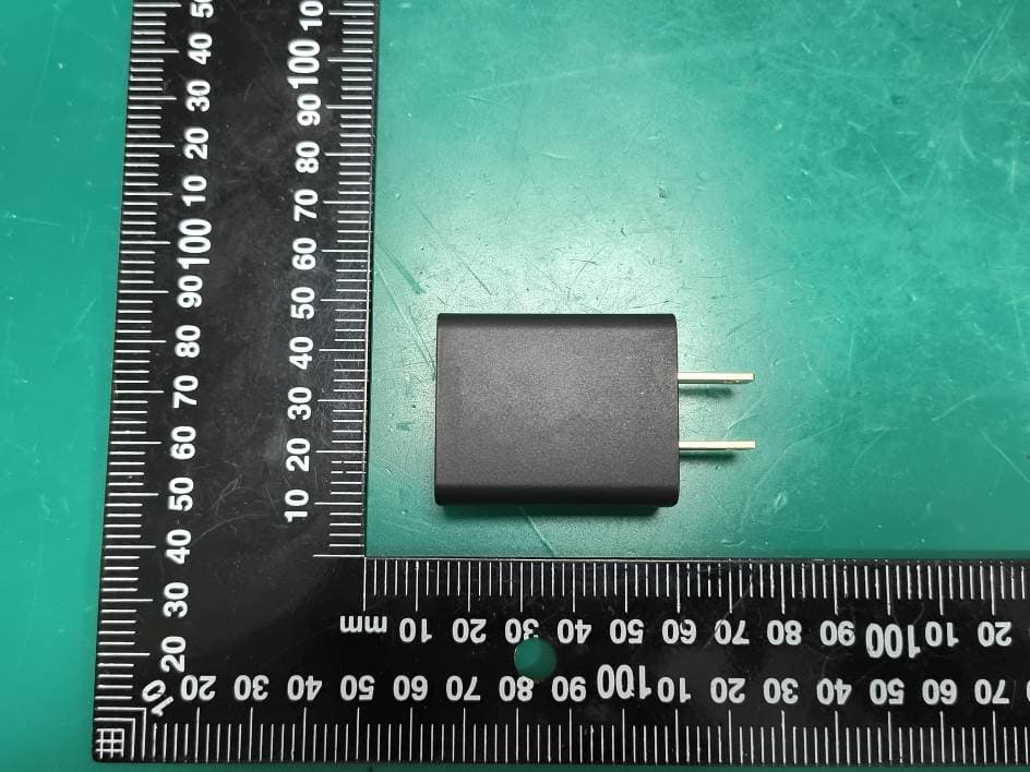
T7HCTH200
Jul 06, 2026Handset
Equipment Class
PUE - Part 15 Unlicensed PCS portable Tx held to ear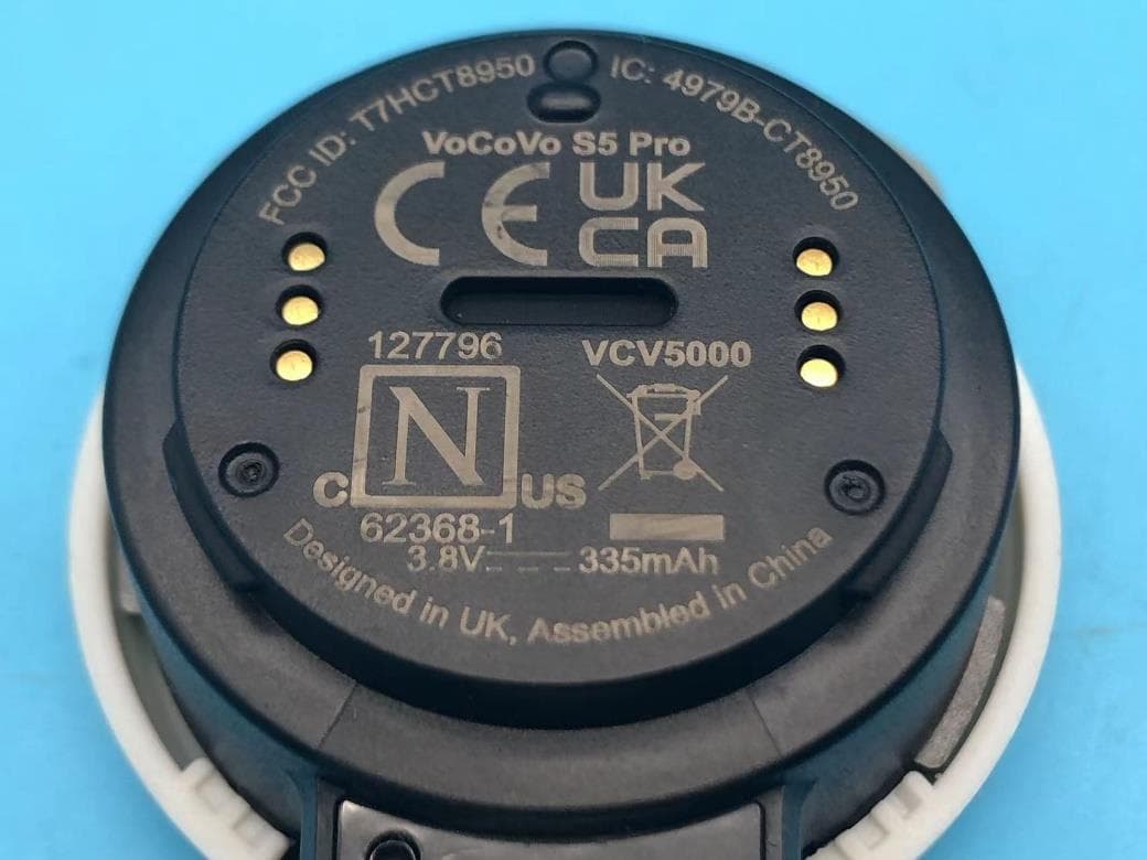
T7HCT8950
May 28, 2023DECT wireless Headset
Equipment Class
PUE - Part 15 Unlicensed PCS portable Tx held to ear
T7HCT8437
Mar 23, 2023Wireless Headset with DECT function
Equipment Class
PUE - Part 15 Unlicensed PCS portable Tx held to ear