T8XWKKBDK2788UHUSB Keyboard
WOLFKING LLC.
Click to zoom
Application Details
- Equipment Class
- JBP - Part 15 Class B Computing Device Peripheral
- Date of Grant
- Nov 08, 2007
- Application Purpose
- Original Equipment
- Date of Application
- Nov 08, 2007
- Equipment Note
- USB Keyboard
- Company
- WOLFKING LLC.
- Country
- United States
Documents & Files
Document Text
Text extracted from the exhibit documents filed with the FCC. Open a document above to read the original.
Block Diagram
Block Diagram Special Controller USB USB HUB1 USB HUB2 M C U Keyboard Matrix P C BACKLIGHT Special key (K Lock ON/OFF & Backlight ON/OFF)
External Photos
EUT EXTERIOR PHOTO Applicant: WOLFKING LLC. FCC ID: T8XWKKBDK2788UH
Internal Photos
EUT INSIDE PHOTO Applicant: WOLFKING LLC. FCC ID: T8XWKKBDK2788UH
Operational Description
Applicant:WOLFKING LLC FCC ID :T8XWKKBDK2788UH The DK –2788UH is a USB keyboard.This keyboard is compatible with IBM pc. It is designed specifically for convenience in a computer game playing . It can be used under Windows 95,Windows 98,Windows CE,Windows 2000 and Windows XP.
Schematics
12345 USB Up Stream CN2 XT AL_ 1 1 XT AL_ 2 2 GN DA 3 VCCA 4 DP2 _PWR 6 DP1 _PWR 8 VCC5V 10 VCC3V 12 USB_D M 13 USB_D P 14 USB1_ DP 15 USB1_ DM 16 GN DIO 18 C0 19 USB2_ DP 21 USB2_ DM 22 C1 24 C2 25 C3 26 C4 27 C5 28 C6 29 C7 30 C8 31 C9 32 CA 33 CB 34 CC 35 CD 36 CE 37 CF 38 CG 39 CH 40 CI 41 R0 42 R1 43 R2 44 R3 45 R4 46 R5 47 R6 48 R7 49 VCCK 50 GN DK 51 B_IN 52 EE P_ EN 53 A_ IN 54 ACPI 55 FN 56 EE P_ CLK 57 EE P_ DA TA 58 ROMSEL3 59 SCR 60 CAPS 61 NU M 62 LE D1 63 LE D2 64 AU 946 2 U1 0. 1uFC13 0. 1uFC12 0. 1uFC11 VCC3. 3 VCCKGN DKVCCAGN DA VCC VCC 39 R8 39 R9 39 R2 39 R3 FB F2 10 uFC4 1. 5K R4 FBF1 1u FC3 VCC3. 3 0. 1uFC15 0. 1uFC20 39 R10 39 R12 39 R13 39 R14 RED LM VD D 0. 1uFC24 0. 1uFC25 0. 1uFC26 FB F3 FB F5 FB F4 FB F6 VCC3. 3VCC3. 3 VCCK GN DK VCCA GN DA 15 KR6 15 KR7 47 pFC16 47 pFC17 15 KR15 15 KR16 47 pFC21 47 pFC22 R7 1 R6 2 R5 3 R4 4 R3 5 R2 6 R1 7 R0 8 C17 9 C16 10 C0 11 C9 12 C8 13 C10 14 C15 15 C11 16 C12 17 C13 18 C14 19 C7 20 C6 21 C5 22 C4 23 C3 24 C2 25 C1 26 KE YBOARD CONJ1 C0C1C2C3C4C5C6C7C8C9C10C11C12C13C14C15C16C17 C0C1C2C3C4C5C6C7C8C9C10C11C12C13C14C15C16C17 R0R1R2R3R4R5R6R7 R0R1R2R3R4R5R6R7 12 MHzY1 18 pF C14 18 pF C18 1234567 Do wns tream GD+D-V2D+D-V1 CN1 33 0 R21 1234567 Do wns tream GD+D-V2D+D-V1 V1 VCC 1 D- 2 D+ 3 GN D 4 LE FT HU BHU B1 VCC 1 D- 2 D+ 3 GN D 4 RIGHT HUBHU B2 10 0u FC110 0u FC2 15 0p FC515 0p FC10 47 pFC6 47 pFC7 47 pFC8 47 pFC9 BLUE LE D1 BLUE LE D2 39 R22 TA CT SW V+ TA CT SW V- TA CT SW Es c TA CT SW Mute C15C1 R3 C16 R6R4 39 R23 VD D CLK 3 D 5 64 Q 1 Q 2 RSTSET CD4013BCMU3 A CLK 11 D 9 810 Q 13 Q 12 SETRST CD4013BCMU3 B 30 K R11 0. 1uFC19 VCC 0. 1uFC23 10 KR17 LE D ON 10 0R5 12 34 PC817U2 VCC3. 3 C6 R2 10 0R1 12345 6 789 10 ABCDEFGH I J KL 1 2 345 6 789 10 PART NO. DESCRIPTION Q`TY MAT'L REMARK SCALE: --- UNIT: --- DRAWN:DESIGER:CHECKED:APPROVED: DRAWING NO.: SHEETDO NO SCALE TITLE: TREATING DRAWING OF ABCD E FGH IJKLMN XT-PCT-1002-02A A4 REV REVER DATE IS SUE MARK M TOLERANCE:UNSPECIFIED.XXX ±0.05.XX ±0.1.X ±0.15. ±0.25 G0 11 11 DK2 788 UH(AU946 2)_ 03 schematic.SCHDOC DK2788UH SCHEMATIC 11 0. 3 SST22 22 A Q1 SST22 22 AQ2 0. 1uFC27 10 KR29 TA CT SW LE DON 30 KR28 1. 5KR27 LE D ON TO LED TO LED 1. 5KR25 K O N K ON 30 KR26 TA CT SW K O N TA CT SW WIN C16 R1
Test Report
FCC CLASS B COMPLIANCE REPORT for Electromagnetic Emissions of Warrior Xxtreme Trade Name : N/A Model Number : DK-2788UH Serial Number : N/A Report Number : ST0710017F FCC ID :T8XWKKBDK2788UH Date : October 23, 2007 Prepared for : WOLFKING LLC. 16 WEST 30 TH STREET, NEW YORK, NY 10001 Prepared by : SINTEK LABORATORY CO., LTD. d.b.a. SINTEK LABORATORY CO., LTD. NO.7, XINSHIDAI INDUSTRIAL,GUANTIAN VILLAGE, SHIYAN TOWN, BAO’AN DISTRICT, SHENZHEN, GUANGDONG, P.R.C TEL:86-755-27604866 FAX:86-755-27608359 Page 1of 24 Rev. 00 TABLE OF CONTENTS DESCRIPTION PAGE VERIFICATION OF COMPLIANCE 3 SYSTEM DESCRIPTION 4 PRODUCT INFORMATION 5 SUPPORT EQUIPMENT 6 SECTION 1 FCC(LINE CONDUCTED & RADIATED EMISSION) 7 MEASUREMENT PROCEDURE & LIMIT (LINE CONDUCTED EMISSION TEST) 7 MEASUREMENT PROCEDURE & LIMIT (RADIATED EMISSION TEST) 10 SUMMARY DATA 13 TEST FACILITY 16 TEST EQUIPMENT LIST 17 BLOCK DIAGRAM OF TEST SETUP 18 APPENDIX 1 PHOTOGRAPHS (TEST SETUP OF LINE CONDUCTED EMISSION) 19 APPENDIX 2 PHOTOGRAPHS (TEST SETUP OF RADIATED EMISSION) 21 APPENDIX 3 PHOTOS OF EUT 23 Page 2 Rev. 00 VERIFICATION OF COMPLIANCE Equipment Under Test: Warrior Xxtreme Trade Name: N/A Model Number: DK-2788UH Serial Number: N/A Applicant: WOLFKING LLC. 16 WEST 30 TH STREET, NEW YORK, NY 10001 Manufacturer: WOLFKING LLC. 16 WEST 30 TH STREET, NEW YORK, NY 10001 Type of Test: FCC Class B Measurement Procedure: ANSI C63.4: 2001 File Number: FCC ID: ST0710017F T8XWKKBDK2788UH Date of test: October 18~23, 2007 Deviation: None Condition of Test Sample: Normal The above equipment was tested by SinTek Laboratory Co.,Ltd. for compliance with the requirements set forth in the FCC Rules and Regulations Part 15, Subpart B and the measurement procedure according to ANSI C63.4. This said equipment in the configuration described in this report shows the maximum emission levels emanating from equipment are within the compliance requirements. The test results of this report relate only to the tested sample identified in this report. Approved by Authorized Signatory: Page 3 Rev. 00 SYSTEM DESCRIPTION EUT Test Program: 1. Set up EUT with the auxiliary equipment. 2. Let the EUT work in test mode and measure it. Page 4 Rev. 00 PRODUCT INFORMATION Housing Type: Plastic EUT Power Rating: DC 5V Power during Test: DC 5V BY PC I/O Port of EUT: I/O Port Type Q’TY Tested with N/A N/A N/A Difference between model numbers as below: Model Number Trade Name N/A N/A Page 5 Rev. 00 SUPPORT EQUIPMENT No.Equipment Model # Serial # Trade Name Data Cable Power Cord 1. PC PC2 N/A N/A N/A Unshielded, 1.8m 2. Printer P320A DQYK006399 EPSON STYLUS C60 Shielded 1.5m Unshielded 1.8m 3. Mouse 3D SWW-22 N/A SHUANGFE IYAN Shielded 1.5m N/A 4. Modem EDVM-CF56T HCF G9TTAI-25564- M5-E WONDA Shielded 1.5 m Unshielded 1.8 m 5 Monitor 170X5 BZ0005261100 36 PHILIPS Shielded 1.5 m Unshielded 1.8m **Note: All the above equipment/cables were placed in worse case positions to maximize emission signals during emission test. Grounding: Grounding was in accordance with the manufacturer’s requirements and conditions for the intended use. Page 6 Rev. 00 SECTION 1 FCC (LINE CONDUCTED AND RADIATED EMISSION) MEASUREMENT PROCEDURE (PRELIMINARY LINE CONDUCTED EMISSION TEST) 1) The equipment was set up as per the test configuration to simulate typical actual usage per the user’s manual. When the EUT is a tabletop system, a wooden table with a height of 0.8 meters is used and is placed on the ground plane as per ANSI C63.4 (see Test Facility for the dimensions of the ground plane used). When the EUT is a floor-standing equipment, it is placed on the ground plane which has a 3-12 mm non-conductive covering to insulate the EUT from the ground plane. 2) Support equipment, if needed, was placed as per ANSI C63.4. 3) All I/O cables were positioned to simulate typical actual usage as per ANSI C63.4. 4) The EUT received DC 5V through PC, and PC received AC120V/60Hz power through a Line Impedance Stabilization Network (LISN) which supplied power source and was grounded to the ground plane 5) All support equipments received 120V/60Hz power from a second LISN, if any. 6) The EUT test program was started. Emissions were measured on each current carrying line of the EUT using a spectrum Analyzer / Receiver connected to the LISN powering the EUT. The LISN has two monitoring points: Line 1 (Hot Side) and Line 2 (Neutral Side). Two scans were taken: one with Line 1 connected to Analyzer / Receiver and Line 2 connected to a 50 ohm load; the second scan had Line 1 connected to a 50 ohm load and Line 2 connected to the Analyzer / Receiver. 7) Analyzer / Receiver scanned from 150kHz to 30MHz for emissions in each of the test modes. 8) During the above scans, the emissions were maximized by cable manipulation. 9) The following test mode(s) were scanned during the preliminary test: Preliminary Conducted Emission Test Frequency Range Investigated 150KHz TO 30 MHz Mode of operation Date Data Report No. Worst Mode NORMAL 10/20/2007 DK-2788UH_0(L,N) Then, the EUT configuration and cable configuration of the above highest emission level were recorded for reference of final testing. Page 7 Rev. 00 MEASUREMENT PROCEDURE (FINAL LINE CONDUCTED EMISSION TEST) 1) EUT and support equipment was set up on the test bench as per step 9 of the preliminary test. 2) A scan was taken on both power lines, Line 1 and Line 2, recording at least the six highest emissions. Emission frequency and amplitude were recorded into a computer in which correction factors were used to calculate the emission level and compare reading to the applicable limit. If EUT emission level was less –2dB to the A.V. limit in Peak mode, then the emission signal was re-checked using an Average detector. 3) The test data of the worst case condition(s) was reported on the Summary Data page. Data Sample: Freq. MHz Peak Raw dBuV Q.P. Raw dBuV Average Raw dBuV Q.P. Limit dBuV Average Limit dBuV Q.P. Margin dB Average Margin dB Note xxx.xxx 43.90 --- --- 56.00 46.00 --- -2…
Text truncated - open the document above for the full version.
Test Report
FCC CLASS B COMPLIANCE REPORT for Electromagnetic Emissions of Warrior Xxtreme Trade Name : N/A Model Number : DK-2788UH Serial Number : N/A Report Number : ST0710017F FCC ID :T8XWKKBDK2788UH Date : October 23, 2007 Prepared for : WOLFKING LLC. 16 WEST 30 TH STREET, NEW YORK, NY 10001 Prepared by : SINTEK LABORATORY CO., LTD. d.b.a. SINTEK LABORATORY CO., LTD. NO.7, XINSHIDAI INDUSTRIAL,GUANTIAN VILLAGE, SHIYAN TOWN, BAO’AN DISTRICT, SHENZHEN, GUANGDONG, P.R.C TEL:86-755-27604866 FAX:86-755-27608359 Page 1of 24 Rev. 00 TABLE OF CONTENTS DESCRIPTION PAGE VERIFICATION OF COMPLIANCE 3 SYSTEM DESCRIPTION 4 PRODUCT INFORMATION 5 SUPPORT EQUIPMENT 6 SECTION 1 FCC(LINE CONDUCTED & RADIATED EMISSION) 7 MEASUREMENT PROCEDURE & LIMIT (LINE CONDUCTED EMISSION TEST) 7 MEASUREMENT PROCEDURE & LIMIT (RADIATED EMISSION TEST) 10 SUMMARY DATA 13 TEST FACILITY 16 TEST EQUIPMENT LIST 17 BLOCK DIAGRAM OF TEST SETUP 18 APPENDIX 1 PHOTOGRAPHS (TEST SETUP OF LINE CONDUCTED EMISSION) 19 APPENDIX 2 PHOTOGRAPHS (TEST SETUP OF RADIATED EMISSION) 21 APPENDIX 3 PHOTOS OF EUT 23 Page 2 Rev. 00 VERIFICATION OF COMPLIANCE Equipment Under Test: Warrior Xxtreme Trade Name: N/A Model Number: DK-2788UH Serial Number: N/A Applicant: WOLFKING LLC. 16 WEST 30 TH STREET, NEW YORK, NY 10001 Manufacturer: WOLFKING LLC. 16 WEST 30 TH STREET, NEW YORK, NY 10001 Type of Test: FCC Class B Measurement Procedure: ANSI C63.4: 2001 File Number: FCC ID: ST0710017F T8XWKKBDK2788UH Date of test: October 18~23, 2007 Deviation: None Condition of Test Sample: Normal The above equipment was tested by SinTek Laboratory Co.,Ltd. for compliance with the requirements set forth in the FCC Rules and Regulations Part 15, Subpart B and the measurement procedure according to ANSI C63.4. This said equipment in the configuration described in this report shows the maximum emission levels emanating from equipment are within the compliance requirements. The test results of this report relate only to the tested sample identified in this report. Approved by Authorized Signatory: Page 3 Rev. 00 SYSTEM DESCRIPTION EUT Test Program: 1. Set up EUT with the auxiliary equipment. 2. Let the EUT work in test mode and measure it. Page 4 Rev. 00 PRODUCT INFORMATION Housing Type: Plastic EUT Power Rating: DC 5V Power during Test: DC 5V BY PC I/O Port of EUT: I/O Port Type Q’TY Tested with N/A N/A N/A Difference between model numbers as below: Model Number Trade Name N/A N/A Page 5 Rev. 00 SUPPORT EQUIPMENT No.Equipment Model # Serial # Trade Name Data Cable Power Cord 1. PC PC2 N/A N/A N/A Unshielded, 1.8m 2. Printer P320A DQYK006399 EPSON STYLUS C60 Shielded 1.5m Unshielded 1.8m 3. Mouse 3D SWW-22 N/A SHUANGFE IYAN Shielded 1.5m N/A 4. Modem EDVM-CF56T HCF G9TTAI-25564- M5-E WONDA Shielded 1.5 m Unshielded 1.8 m 5 Monitor 170X5 BZ0005261100 36 PHILIPS Shielded 1.5 m Unshielded 1.8m **Note: All the above equipment/cables were placed in worse case positions to maximize emission signals during emission test. Grounding: Grounding was in accordance with the manufacturer’s requirements and conditions for the intended use. Page 6 Rev. 00 SECTION 1 FCC (LINE CONDUCTED AND RADIATED EMISSION) MEASUREMENT PROCEDURE (PRELIMINARY LINE CONDUCTED EMISSION TEST) 1) The equipment was set up as per the test configuration to simulate typical actual usage per the user’s manual. When the EUT is a tabletop system, a wooden table with a height of 0.8 meters is used and is placed on the ground plane as per ANSI C63.4 (see Test Facility for the dimensions of the ground plane used). When the EUT is a floor-standing equipment, it is placed on the ground plane which has a 3-12 mm non-conductive covering to insulate the EUT from the ground plane. 2) Support equipment, if needed, was placed as per ANSI C63.4. 3) All I/O cables were positioned to simulate typical actual usage as per ANSI C63.4. 4) The EUT received DC 5V through PC, and PC received AC120V/60Hz power through a Line Impedance Stabilization Network (LISN) which supplied power source and was grounded to the ground plane 5) All support equipments received 120V/60Hz power from a second LISN, if any. 6) The EUT test program was started. Emissions were measured on each current carrying line of the EUT using a spectrum Analyzer / Receiver connected to the LISN powering the EUT. The LISN has two monitoring points: Line 1 (Hot Side) and Line 2 (Neutral Side). Two scans were taken: one with Line 1 connected to Analyzer / Receiver and Line 2 connected to a 50 ohm load; the second scan had Line 1 connected to a 50 ohm load and Line 2 connected to the Analyzer / Receiver. 7) Analyzer / Receiver scanned from 150kHz to 30MHz for emissions in each of the test modes. 8) During the above scans, the emissions were maximized by cable manipulation. 9) The following test mode(s) were scanned during the preliminary test: Preliminary Conducted Emission Test Frequency Range Investigated 150KHz TO 30 MHz Mode of operation Date Data Report No. Worst Mode NORMAL 10/20/2007 DK-2788UH_0(L,N) Then, the EUT configuration and cable configuration of the above highest emission level were recorded for reference of final testing. Page 7 Rev. 00 MEASUREMENT PROCEDURE (FINAL LINE CONDUCTED EMISSION TEST) 1) EUT and support equipment was set up on the test bench as per step 9 of the preliminary test. 2) A scan was taken on both power lines, Line 1 and Line 2, recording at least the six highest emissions. Emission frequency and amplitude were recorded into a computer in which correction factors were used to calculate the emission level and compare reading to the applicable limit. If EUT emission level was less –2dB to the A.V. limit in Peak mode, then the emission signal was re-checked using an Average detector. 3) The test data of the worst case condition(s) was reported on the Summary Data page. Data Sample: Freq. MHz Peak Raw dBuV Q.P. Raw dBuV Average Raw dBuV Q.P. Limit dBuV Average Limit dBuV Q.P. Margin dB Average Margin dB Note xxx.xxx 43.90 --- --- 56.00 46.00 --- -2…
Text truncated - open the document above for the full version.
Test Setup Photos
TEST SETUP PHOTO Applicant: WOLFKING LLC. FCC ID: T8XWKKBDK2788UH LINE CONDUCTED EMISSION TEST RADIATED EMISSION TEST
Contact Information
Applicant
Patrick Chan(Engineer)
Test Firm
SinTek Laboratory Co., Ltd.Eric Lin
Technical Specifications
| # | Rule Parts | Frequency Range | Power Output |
|---|---|---|---|
| 1 | 15B | - | - |
Other Applications from WOLFKING LLC.
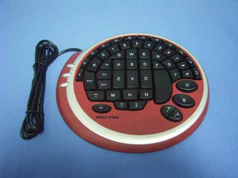
T8XWKKBDK2388U
May 15, 2006WOLFKING keyboard
Equipment Class
JBP - Part 15 Class B Computing Device Peripheral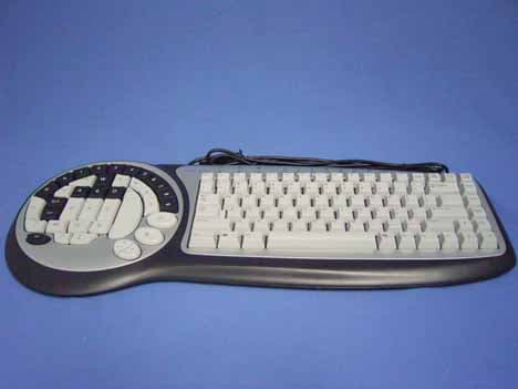
T8XWKKBDK2588UH
May 15, 2006WOLFKING keyboard
Equipment Class
JBP - Part 15 Class B Computing Device Peripheral