T9P-27988A2.4GHz 30 Channel Analog Cordless Phone w/ CID
GTC Electronics Ltd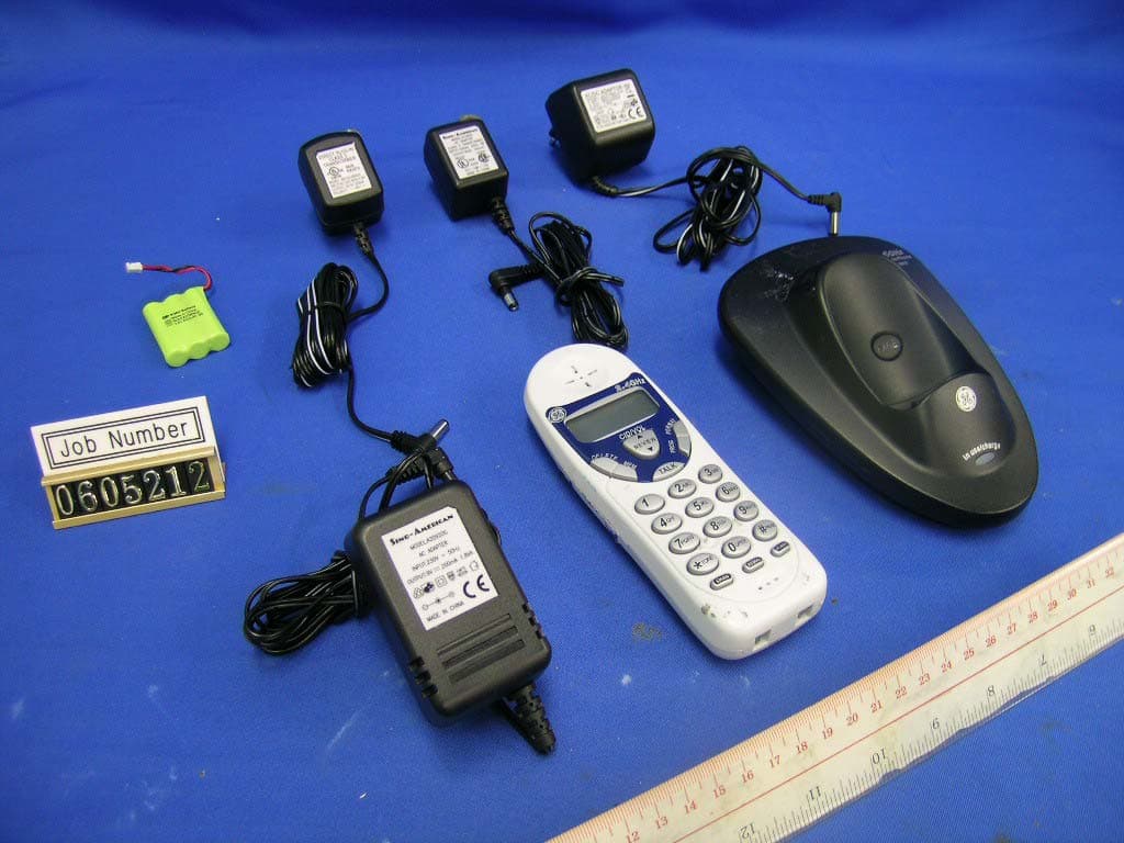
Click to zoom
Application Details
- Equipment Class
- DXT - Part 15 Low Power Transceiver, Rx Verified
- Date of Grant
- Jul 17, 2006
- Application Purpose
- Original Equipment
- Date of Application
- Jul 17, 2006
- Equipment Note
- 2.4GHz 30 Channel Analog Cordless Phone w/ CID
- Frequency Range
- 2470.20000000 - 2478.90000000
- Company
- GTC Electronics Ltd
- Country
- Hong Kong
Documents & Files
Document Text
Text extracted from the exhibit documents filed with the FCC. Open a document above to read the original.
Users Manual
IMPORTANT INSTALLATION INFORMATION Never install telephone wiring during a lightning storm. Never install telephone jacks in wet locations unless the jack is specifically designed for wet locations. Never touch uninsulated telephone wires or terminals, unless the telephone line has been disconnected at the network interface. Use caution when installing or modifying telephone lines. Temporarily disconnect any equipment connected to the phone such as faxes, other phones, or modems. INSTALLING THE PHONE Your telephone should be placed on a level surface such as a desk or table top. NOTE: The handset must be charged facing up. 1 2 NOTE : You must connect the handset battery before use. INSTALLING THE HANDSET BATTERY BLACK WIRE BATTERY RED WIRE PRESS DOWN FIRMLY 1. Push down on the top of the battery compartment door (located on the back of handset) and remove it. 2. Lift the battery pack and connect it's plug to the jack inside the compartment. NOTE : It is important to maintain the polarity (black and red wires) to the jack inside the compartment as shown in the illustration. 3. Close the battery compartment by pushing the cover up until it snaps into place. 4. Place the handset in the charging cradle. CONNECTING THE AC (ELECTRICAL) POWER Plug the power supply cord into the power jack on the back of the base and the other end into an electrical outlet. The charge/in use indicator turns On to indicate the battery is charging when the handset is placed on the base cradle. Allow the phone to charge for 12 hours prior to first use. If you don't properly charge the phone, battery performance is compromised. NOTE: If the battery is not installed in the handset, or if the battery pack is not properly connected to the jack inside the battery compartment, Battery-low icon shows in the display when the handset is placed in the charging cradle. CAUTION: Use only the ATLINKS USA, Inc. power supply that came with this unit. Using other power supplies may damage the unit. Plug the adaptor to the socket-outlet that near the equipment and shall be easily accessible. CONNECTING THE TELEPHONE LINE Plug the one end of the telephone line cord into the jack marked TEL LINE on the back of the base and the other end into a modular wall phone jack. NOTE: The phone is shipped from the manufacturer in tone dialing mode. and the ringer loudness in higher level. SET UP FLASH TIME 1. Press the PROG button then REVIEW up / down until 'SET 5 FLASH' shows in the display. 2. Press the PROG button again to enter the set mode. The wordings '600' (default) is flashing. 3. Use the REVIEW up / down to change the setting between 100, 200 or 300ms. 4. Press the PROG button to confirm the setting. 2. To hang up, press the TALK button or place the handset in the base cradle. CHAN button FLASH/EXIT button REDIAL button RECEIVING A CALL 1. To answer a call press the TALK button on the handset before you begin speaking. REVIEW ( or ) button DELETE button MEM button TALK button FORMAT button PROG button Display CORDLESS PHONE BASICS 30-Channel 2.4 GHz Cordless Telephone with dual mode Caller ID User's Guide EX27988 INTRODUCTION CAUTION: When using telephone equipment, there are basic safety instructions that should always be followed. Refer to the IMPORTANT SAFETY INSTRUCTIONS provided with this product and save them for future reference. Your Caller ID phone stores and displays specific information, provided by your local telephone company, to subscribers of Caller ID or similar caller identification services. You must subscribe to one of these services in order to use this unit. Your Caller ID phone enables you to: Identify callers before you answer the phone. View the time and date of each incoming call. Record up to 50 Caller ID messages sequentially. Know who called while you were away. To get the most from your new phone, we suggest that you take a few minutes right now to read through this user's guide. IMPORTANT: In order to use all of the features of this unit, you must subscribe to the standard Number Caller ID Service . IMPORTANT: Because cordless phones operate on electricity, you should have at least one phone in your home that isn't cordless, in case the power in your home goes out. WARNING: TO PREVENT FIRE OR ELECTRICAL SHOCK HAZARD, DO NOT EXPOSE THIS PRODUCT TO RAIN OR MOISTURE. THE LIGHTNING FLASH AND ARROW HEAD WITHIN THE TRIANGLE IS A WARNING SIGN ALERTING YOU OF " DANGEROUS VOLTAGE" INSIDE THE PRODUCT. CAUTION: TO REDUCE THE RISK OF ELECTRIC SHOCK, DO NOT REMOVE COVER (OR BACK). NO USER SERVICEABLE PARTS INSIDE. REFER SERVICING TO QUALIFIED SERVICE PERSONNEL. RISK OF ELECTRIC SHOCK DO NOT OPEN CAUTION: SEE MARKING ON BOTTOM / BACK OF PRODUCT THE EXCLAMATION POINT WITHIN THE TRIANGLE IS A WARNING SIGN ALERTING YOU OF IMPORTANT INSTRUCTIONS ACCOMPANYING THE PRODUCT. There are six programmable menus available: 1) Date / Time. 2) Local Area Code. 3) Ringer Loudness. 4) Tone / Pulse. 5) Flash Time. 6) Song. Press PROG button to enter the program mode in menu 1, It can be changed by REVIEW up /down button. During the program mode, you can press the FLASH button to exit the menu. If no action within 20sec, your handset will return to standby mode. Model EX27988 00014865 (Rev. 0 E) 06-20 Printed in China BEFORE YOU BEGIN PARTS CHECKLIST Make sure your package includes the items shown here. BaseHandset Handset battery AC power supply Telephone line cord MODULAR JACK REQUIREMENTS You will need an RJ11C type modular phone jack, which is the most common type of phone jack and might look like the one pictured here. If you don't have a modular jack, call your local phone company to find out how to get one installed. Wall plate Modular telephone line jack INSTALLATION NOTE: Some cordless telephones operate at frequencies that may cause interference to nearby TVs, microwave ovens, and VCRs. To minimize or prevent such interference, the base of the cordless telephone should not be placed near or on top of a TV, microwave ovens, or …
Text truncated - open the document above for the full version.
External Photos
INTERTEK TESTING SERVICES External Photos FCC ID: T9P-27988A external photos - 1 of 2 INTERTEK TESTING SERVICES External Photos FCC ID: T9P-27988A external photos - 2 of 2
Internal Photos
INTERTEK TESTING SERVICES Internal photos FCC ID: T9P-27988A internal photos - 1 of 7 Base Unit assembly Base Unit Main PCB comp side (View 1) INTERTEK TESTING SERVICES Internal photos FCC ID: T9P-27988A internal photos - 2 of 7 Base Unit Main PCB comp side (View 2) Base Unit Main PCB solder side INTERTEK TESTING SERVICES Internal photos FCC ID: T9P-27988A internal photos - 3 of 7 Base Unit Oscillator PCB comp side Base Unit Oscillator PCB solder side INTERTEK TESTING SERVICES Internal photos FCC ID: T9P-27988A internal photos - 4 of 7 Handset assembly Handset Main PCB comp side (View 1) INTERTEK TESTING SERVICES Internal photos FCC ID: T9P-27988A internal photos - 5 of 7 Handset Main PCB comp side (View 2) Handset Main PCB display side (View 1) INTERTEK TESTING SERVICES Internal photos FCC ID: T9P-27988A internal photos - 6 of 7 Handset Main PCB display side (View 2) Handset Oscillator PCB comp side INTERTEK TESTING SERVICES Internal photos FCC ID: T9P-27988A internal photos - 7 of 7 Handset Oscillator PCB solder side
Test Report
INTERTEK TESTING SERVICES Radiated Emission on the Bandedge Plots FCC ID: T9P-27988A emission - 1 of 2 Plot B1A Plot B1B INTERTEK TESTING SERVICES Radiated Emission on the Bandedge Plots FCC ID: T9P-27988A emission - 2 of 2 Plot H1A Plot H1B
Test Report
Report No.: 0605212 Model: MA132-090020 Talk Mode Ctrl No.: N/A PAGE 1 Tested By:Hong, Report No.:0605212 Scan Settings (1 Range) |--------- Frequencies -----------||----------- Receiver Settings ------------| Start Stop Step IF BW Detector M-Time Atten Preamp OpRge 150k 30M 5k 10k PK+AV 10ms AUTO LN OFF 60dB Final Measurement: x QP / + AV Meas Time: 1 s Subranges: 16 Acc Margin: 20dB Transducer No. Start Stop Name 2 1 9k 30M EW0699 12 9k 30M EW0192 0 10 20 30 40 50 60 70 80 90 dBuV 100 0.15 MHz 30 110 F15Q F15A Report No.: 0605212 Model: MA132-090020 Talk Mode Ctrl No.: N/A Tested By:Hong, Report No.:0605212 Scan Settings (1 Range) |--------- Frequencies -----------||----------- Receiver Settings ------------| Start Stop Step IF BW Detector M-Time Atten Preamp OpRge 150k 30M 5k 10k PK+AV 10ms AUTO LN OFF 60dB Final Measurement Results: Frequency QP Level QP Limit MHz dBuV dBuV 0.38500 32.3 58.1 0.41000 32.2 57.7 Frequency AV Level AV Limit MHz dBuV dBuV no Results * limit
Test Setup Photos
INTERTEK TESTING SERVICES The Worst Case Configuration Photographs FCC ID: T9P-27988A config photos (radiated emission - handset) - 1 of 1 Radiated Emission – Base Unit Front View Rear View INTERTEK TESTING SERVICES The Worst Case Configuration Photographs FCC ID: T9P-27988A config photos (radiated emission - handset) - 2 of 2 Radiated Emission – Handset Front View Rear View INTERTEK TESTING SERVICES The Worst Case Configuration Photographs FCC ID: T9P-27988A config photos (conducted emission) - 1 of 2 Conducted Emission Front View Right Side View INTERTEK TESTING SERVICES The Worst Case Configuration Photographs FCC ID: T9P-27988A config photos (conducted emission) - 2 of 2 Conducted Emission Left Side View
Contact Information
Applicant
Alan Lam
Technical Contact
Intertek Testing Services Hong Kong Ltd.Tommy Leung
[email protected]852-2173-8538
2/F., Garment Centre, · Kowloon · Hong Kong
Non-Technical Contact
Intertek Testing Services Hong Kong Ltd.Tommy Leung
[email protected]852-2173-8538
Test Firm
Intertek Testing Services Hong KongBilly Chow
Technical Specifications
| # | Rule Parts | Frequency Range | Power Output |
|---|---|---|---|
| 2 | 15C | 2.47 GHz - 2.48 GHz | - |