T9WXSCC3GSM/GPRS/UMTS/HSDPA QUAD BAND PC DATA CARD
4G Systems GmbH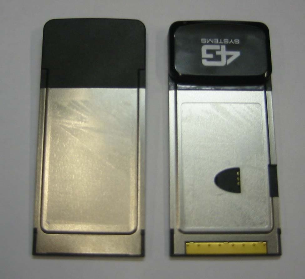
Click to zoom
Application Details
- Equipment Class
- PCB - PCS Licensed Transmitter
- Date of Grant
- Nov 15, 2006
- Application Purpose
- Original Equipment
- Date of Application
- Nov 15, 2006
- Equipment Note
- GSM/GPRS/UMTS/HSDPA QUAD BAND PC DATA CARD
- Frequency Range
- 1850.20000000 - 1909.80000000
- Company
- 4G Systems GmbH
- Country
- Germany
Documents & Files
Document Text
Text extracted from the exhibit documents filed with the FCC. Open a document above to read the original.
Users Manual
4G Systems Data Card User Manual VERSION 1.2 User Manual_4G Systems Data Suite.book Page 1 Wednesday, December 7, 2005 11:40 AM Copyright © 2005 4G Systems GmbH. All rights reserved worldwide. This document and the related software are property of 4G Systems GmbH or its suppliers and protected by copyright and other laws. They are distributed under licenses restricting their use, copying, distribution, and decompilation. Neither receipt nor possession of this document confers or transfers any right to reproduce or disclose any part of the contents hereof. No part of this document may be reproduced in any form by any means without prior written authorization of 4G Systems GmbH. Moreover, the regulations of the software license agreement apply to this documentation. All brand names and trademarks mentioned are the property of their respective owners. http://www.4g-systems.com User Manual_4G Systems Data Suite.book Page 2 Wednesday, December 7, 2005 11:40 AM User Manual3 Table of Contents Chapter 1Introduction5 About this Manual 5 System Requirements 6 Typographical Conventions 7 Chapter 2Installing the Data Suite9 Chapter 3First Steps15 User Interface of the Data Suite 15 The Info Sub-menu 21 Options and Preferences 22 Chapter 4Installing Devices31 General Procedure 31 Installing a Bluetooth Phone 35 Installing Multiple Devices 37 Device Lists 38 Chapter 5Connections41 Default Connection Settings 41 Automatic Connections 44 Manual Connections 53 Roaming 55 Chapter 6Extending the Data Suite59 Working with Modules 60 SMS Manager Module 64 Phonebook Manager Module 69 User Manual_4G Systems Data Suite.book Page 3 Wednesday, December 7, 2005 11:40 AM 44G Systems Data Suite Usage Manager Module 73 RSS Feed Module 78 Hotspots Module 81 Index83 User Manual_4G Systems Data Suite.book Page 4 Wednesday, December 7, 2005 11:40 AM User Manual5 CHAPTER 1 1Introduction Welcome to the 4G Systems Data Suite (Data Suite for short). In this manual, we explain the functionality and usage of the Data Suite. About this Manual The contents of this manual are organized as follows: Chapter 2 Installing the Data Suite explains the procedure of installing a new Data Suite. Chapter 3 First Steps introduces the user interface of the Data Suite and shows. This chapter also explains how to tailor the Data Suite to your needs. Chapter 4 Installing Devices shows you how to install a mobile or WLAN device. Chapter 5 Connections describes the way the Data Suite handles connections. Both, automatic and manual connections are recog- nized by the Data Suite. The differences between these two connection types are explained here. You will also learn how to create a new automatic connection. In Chapter 6 Extending the Data Suite you will learn how to increase the functionality of the Data Suite by using modules. The information contained in this manual is also available via the help icon of the Data Suite. User Manual_4G Systems Data Suite.book Page 5 Wednesday, December 7, 2005 11:40 AM 64G Systems Data Suite Chapter 1 System Requirements Minimum hardware requirements 100 MB free hard disk space 32 MB RAM screen resolution 800 x 600 or higher color quality 16 bits or higher Operating system Microsoft Windows 2000 or Microsoft Windows XP administrator rights on your PC to install and use the Data Suite Connectivity for mobile or WLAN datacard: free PC card slot (PCMCIA Type II) for HSDPA, UMTS, EDGE, GPRS, CSD or any other mobile operator service: mobile datacard or mobile phone mobile data connection enabled SIM card for WLAN: WLAN datacard or laptop with WLAN built in User Manual_4G Systems Data Suite.book Page 6 Wednesday, December 7, 2005 11:40 AM Introduction User Manual7 Typographical Conventions The following conventions are used in the text to draw attention to program elements, etc.: Safety instructions. To avoid hurting yourself or doing damage to the electronic device, please keep the following tips in mind when installing and using the data card. The 4G Systems data card is a mobile electronic device, and is only intended for use in heated, dry, and dustfree spaces. The device may not be mounted or placed in a location subject to direct sunlight or the effects of heat. The air slots and openings in the device are for ElementFont or symbol Program interface such as menu commands, windows, dialog boxes, field and button names Menu > Entry Paths to directories, file and direc- tory names Drive:\Directory\File name Quotations from program code or configuration files Code quotations Variables, i.e. placeholders for specific elements {variable} Important information and warnings are enclosed in gray boxes. Make sure to read such information to avoid losing data or making errors when using and managing WCM systems. 84G Systems Data Suite Chapter 1 ventilation purposes. These openings must not be covered or obstructed. The device must not come into contact with any liquids, as this can lead to electric shock or short circuit, and can cause irreparable damage to the device. Do not open the case of your data card. If the case is opened by unauthorized persons, or inexpert repairs are attempted, all warranty agreements become null and void. Furthermore, such actions are dangerous for users and can lead to damage to the device. The device should not be exposed to fi re or other heat sources, and it should not be used in locations with a potentially explosive atmosphere. The device should not be installed during a thunderstorm, and should remain unplugged during installation procedures. The electronic interference produced by the device may affect the electronic systems and navigational systems in airplanes, and for this reason, the use of this device on board aircraft is prohibited by law in most countries. Do not operate the device near medical equipment without prior permission. The PCMCIA card has to be supplied by a Limited Power Source in accordance with EN 60950-1:2001*. *Note: The environment temper…
Text truncated - open the document above for the full version.
Users Manual
4G Systems NCX-1 / NCXV-1 PC Data Card Federal communications commission notice This equipment has been tested and found to comply with the limits for a Class B digital device, pursuant to Part 15 of the FCC Rules. These limits are designed to provide reasonable protection against harmful interference in a residential installation. This equipment generates, uses, and can radiate radio frequency energy and, if not installed and used in accordance with the instructions, may cause harmful interference to radio communications. However, there is no guarantee that interference will not occur in a particular installation. If this equipment does cause harmful interference to radio or television reception, which can be determined by turning the equipment off and on, the user is encouraged to try to correct the interference by one or more of the following measures: • Reorient or relocate the receiving antenna. • Increase the separation between the equipment and receiver. • Connect the equipment into an outlet on a circuit different from that to which the receiver is connected. • Consult the dealer or an experienced radio or television technician for help. • Modifications The FCC requires the user to be notified that any changes or modifications made to this device that are not expressly approved by 4G Systems could void the user's authority to operate the equipment. Cables Connections to this device must be made with shielded cables with metallic RFI/EMI connector hoods in order to maintain compliance with FCC Rules and Regulations. Declaration of Conformity for products marked with the FCC logo United States only This device complies with Part 15 of the FCC rules. Operation is subject to the following two conditions: • this device may not cause harmful interference, and • this device must accept any interference received, including interference that may cause undesired operation. To identify this product, refer to the Part, Series, or Model number found on the product. This product has successfully completed the PTCRB requirements governing the release of new GSM 850/1900 capable products into the North American market. Exposure Information to Radio Frequency Energy This PCMCIA card has been tested in different notebooks for compliance with the SAR requirements. Measured SAR values according to the CE regulations: The maximum measured body SAR value (averaged over a mass of 10 g and distance between phantom and antenna of 5 mm) is well below the limit of 2 W/kg. Measured SAR values according to the FCC regulations: The maximum measured body SAR value (averaged over a mass of 1 g and distance between phantom and antenna of 5 mm) is well below the limit of 1.6 W/kg. For safe and efficient use the user should keep the antenna of the card at a minimum distance of 1 cm away from his body. All of the measurements above were performed at a distance of 0.5 cm from the body of the user. CAUTION: Users concerned with the risk of Radio Frequency exposure may wish to limit the duration of their calls and to position the antenna as far away from the body as is practical. For questions regarding your product or FCC declaration, contact: 4G Systems GmbH - Jarrestr. 4 - 22303 Hamburg - Germany - www.4g- systems.com 4G Systems NCX-1 / NCXV-1 PC Data Card Canadian Compliance Statement This Class B Digital apparatus meets all the requirements of the Canadian Interference-Causing Equipment Regulations. Cet appareil numerique de la classe B respecte les exigences du Reglement sur le material broilleur du Canada. This device complies with Class B Limits of Industry Canada. Operation is subject to the following two conditions: 1. This device may not cause harmful interference, and 2. This device must accept any interference received, including interference that may cause undesired operation. 4G Systems Data Card NCX-1 and NCXV-1 are certified to the requirements of RSS-132 and RSS-133. For further information, contact your local Industry Canada office.
Users Manual
4G Systems NCX-1 / NCXV-1 PC Data Card Federal communications commission notice This equipment has been tested and found to comply with the limits for a Class B digital device, pursuant to Part 15 of the FCC Rules. These limits are designed to provide reasonable protection against harmful interference in a residential installation. This equipment generates, uses, and can radiate radio frequency energy and, if not installed and used in accordance with the instructions, may cause harmful interference to radio communications. However, there is no guarantee that interference will not occur in a particular installation. If this equipment does cause harmful interference to radio or television reception, which can be determined by turning the equipment off and on, the user is encouraged to try to correct the interference by one or more of the following measures: • Reorient or relocate the receiving antenna. • Increase the separation between the equipment and receiver. • Connect the equipment into an outlet on a circuit different from that to which the receiver is connected. • Consult the dealer or an experienced radio or television technician for help. • Modifications The FCC requires the user to be notified that any changes or modifications made to this device that are not expressly approved by 4G Systems could void the user's authority to operate the equipment. Cables Connections to this device must be made with shielded cables with metallic RFI/EMI connector hoods in order to maintain compliance with FCC Rules and Regulations. Declaration of Conformity for products marked with the FCC logo United States only This device complies with Part 15 of the FCC rules. Operation is subject to the following two conditions: • this device may not cause harmful interference, and • this device must accept any interference received, including interference that may cause undesired operation. To identify this product, refer to the Part, Series, or Model number found on the product. This product has successfully completed the PTCRB requirements governing the release of new GSM 850/1900 capable products into the North American market. Exposure Information to Radio Frequency Energy This PCMCIA card has been tested in different notebooks for compliance with the SAR requirements. Measured SAR values according to the CE regulations: The maximum measured body SAR value (averaged over a mass of 10 g and distance between phantom and antenna of 5 mm) is well below the limit of 2 W/kg. Measured SAR values according to the FCC regulations: The maximum measured body SAR value (averaged over a mass of 1 g and distance between phantom and antenna of 5 mm) is well below the limit of 1.6 W/kg. For safe and efficient use the user should keep the antenna of the card at a minimum distance of 1 cm away from his body. All of the measurements above were performed at a distance of 0.5 cm from the body of the user. CAUTION: Users concerned with the risk of Radio Frequency exposure may wish to limit the duration of their calls and to position the antenna as far away from the body as is practical. For questions regarding your product or FCC declaration, contact: 4G Systems GmbH - Jarrestr. 4 - 22303 Hamburg - Germany - www.4g- systems.com 4G Systems NCX-1 / NCXV-1 PC Data Card Canadian Compliance Statement This Class B Digital apparatus meets all the requirements of the Canadian Interference-Causing Equipment Regulations. Cet appareil numerique de la classe B respecte les exigences du Reglement sur le material broilleur du Canada. This device complies with Class B Limits of Industry Canada. Operation is subject to the following two conditions: 1. This device may not cause harmful interference, and 2. This device must accept any interference received, including interference that may cause undesired operation. 4G Systems Data Card NCX-1 and NCXV-1 are certified to the requirements of RSS-132 and RSS-133. For further information, contact your local Industry Canada office.
ID Label/Location Info
ARTWORK NOTES:1. MATERIAL - POLYESTER , MAX THICKNESS 0.05mm.2. FINISH - GLOSS SURFACE TEXTURE, SELF ADHESIVE TO BE APPLIED TO REAR OFLABEL, 3M 467 OR EQUIVALENT MAX THICKNESS 0.025mm.3. LABELS TO BE SUPPLIED IN ROLL FORM, INSIDE DIAMETER 76mm.4. ALL FIELDS IDENTIFIED BY BROKEN LINE AND TEXT ‘IMEI’ & ‘Made In Germany’ TO BEPRINTED AT SIEMENS FACTORY.5. ENVIRONMENTAL SPECIFICATION: OPERATING TEMPERATURE -40 TO BE RESISTANT TO UV RADIATION, COMMON POLLUTANTS SUCH AS BLOOD, SALT WATER, DETERGENTS ETC.6. ARTWORK TO BE PROVIDED IN COREL DRAW FORMAT (*.CDR) BY ROKE MANOR ºC TO +85ºC, 95% RELATIVE HUMIDITY, R1.454 CORNERS 1:1 LABEL BOTTOM Dustin () Z30880-S8220-Z5 SEE NOTE 1 1- 1 +/- 0.2 41.2 63.0 LABEL DIMENSIONS IMEI No. BARCODE CODE 128 SIZE 1 RATIO: 2.0 HEIGHT: 3.0 (SEE NOTE 4) IMEI No. 2D BARCODE5.0 x 5.0(SEE NOTE 4) DATECODE ACCORDING IEC62 HEIGHT: 2.0 (SEE NOTE 4) IMEI NUMBERHEIGHT: 2.0(SEE NOTE 4) 1 3 Z30880-S8220-Z5 COLOUR REF. DESCRIPTION WHITEBLACKPANTONECOOL GREY 3C BACKGROUNDMAIN TEXTGRID COLOUR PANTONERED/ORANGE172C 4G LOGO TEXT(SEE NOTE 4) TEXT (SEE NOTE 4) EH 09.07.06 05.06.06 E. Hobby 2 EH 04.09.06 0700 FCC ID: T9WXSCC3 Pb XS Card C3 (NCX1) Model: IMEI No: Made In Germany 3 EH 29.09.06
ID Label/Location Info
ARTWORK NOTES:1. MATERIAL - POLYESTER , MAX THICKNESS 0.05mm.2. FINISH - GLOSS SURFACE TEXTURE, SELF ADHESIVE TO BE APPLIED TO REAR OFLABEL, 3M 467 OR EQUIVALENT MAX THICKNESS 0.025mm.3. LABELS TO BE SUPPLIED IN ROLL FORM, INSIDE DIAMETER 76mm.4. ALL FIELDS IDENTIFIED BY BROKEN LINE AND TEXT ‘IMEI’ & ‘Made In Germany’ TO BEPRINTED AT SIEMENS FACTORY.5. ENVIRONMENTAL SPECIFICATION: OPERATING TEMPERATURE -40 TO BE RESISTANT TO UV RADIATION, COMMON POLLUTANTS SUCH AS BLOOD, SALT WATER, DETERGENTS ETC.6. ARTWORK TO BE PROVIDED IN COREL DRAW FORMAT (*.CDR) BY ROKE MANOR ºC TO +85ºC, 95% RELATIVE HUMIDITY, R1.454 CORNERS 1:1 LABEL BOTTOM Dustin () Z30880-S8220-Z5 SEE NOTE 1 1- 1 +/- 0.2 41.2 63.0 LABEL DIMENSIONS IMEI No. BARCODE CODE 128 SIZE 1 RATIO: 2.0 HEIGHT: 3.0 (SEE NOTE 4) IMEI No. 2D BARCODE5.0 x 5.0(SEE NOTE 4) DATECODE ACCORDING IEC62 HEIGHT: 2.0 (SEE NOTE 4) IMEI NUMBERHEIGHT: 2.0(SEE NOTE 4) 1 3 Z30880-S8220-Z5 COLOUR REF. DESCRIPTION WHITEBLACKPANTONECOOL GREY 3C BACKGROUNDMAIN TEXTGRID COLOUR PANTONERED/ORANGE172C 4G LOGO TEXT(SEE NOTE 4) TEXT (SEE NOTE 4) EH 09.07.06 05.06.06 E. Hobby 2 EH 04.09.06 0700 FCC ID: T9WXSCC3 Pb XS Card C3 (NCX1) Model: IMEI No: Made In Germany 3 EH 29.09.06
Operational Description
siemens Communications Wireless Modules Hardware Specification Version 01/0 Dustin CONFIDENTIAL 060928_dustin_hw_specification_datacard.doc For internal use only Page 1 of 57 Com WM RD Dustin: Datacard Variant Hardware Specification Status: Released/Reviewed Document: 060928_Dustin_HW_Specification_datacard.doc Version: 01/06 Copyright (C) Siemens AG 2004 This document may not be passed on, copied or used, nor may its content be communicated to third parties without express permission. Violation of this provision will result in compensation claims. All rights reserved in the event of patenting or registration of utility model. Payment of compensation will be required of anyone acting against this. Released by: Date / Sign Published by the Com WM RD HW 1 Siemens AG 13629 Berlin Germany Roke Manor Research Limited 28 September 2006/ C Edwards siemens Communications Wireless Modules Hardware Specification Version 01/0 Dustin CONFIDENTIAL 060928_dustin_hw_specification_datacard.doc For internal use only Page 2 of 57 Document: Dustin_HW_Specification .doc Archive Revision: Authors: Chris Edwards, Rob Clifford, Michael Weyrauch Date: 15.12.2004 Archive: Revision History Status Date Author Reason for Change 01/01 02.08.2004 Chris Edwards Created – based on Maja HW Spec 01/02 15.12.2004 Rob Clifford/Michael Weyrauch Updated to latest Qualcomm architecture 01/03 01.06.2005 Russell Taylor Minimum voltage changed to 3.1V 01/04 22.03.2006 Chris Edwards Update 01/05 10.09.2006 Colin Drysdale Remove references to the US build. 01/06 28.09.2006 Colin Drysdale Updated the block diagrams and removed all references to Audio. Authors Author Department Chapter Function Chris Edwards RMRL Creator/ Author Rob Clifford RMRL Michael Weyrauch Com WM RD 5 siemens Communications Wireless Modules Hardware Specification Version 01/0 Dustin CONFIDENTIAL 060928_dustin_hw_specification_datacard.doc For internal use only Page 3 of 57 Contents 1 INTRODUCTION..........................................................................................................................................6 1.1 DUSTIN ROUTER AND PCC AND BUILDS...................................................................................................6 1.2 REFERENCED DOCUMENTS.......................................................................................................................6 2 COMPLIANCE DOCUMENTS ...................................................................................................................6 3 PRODUCT CONCEPT .................................................................................................................................6 3.1 BLOCK DIAGRAM FOR PRODUCT CONCEPT...............................................................................................6 4 CIRCUIT CONCEPT ....................................................................................................................................6 4.1 BLOCK DIAGRAM FOR CIRCUIT CONCEPT.................................................................................................6 4.2 FUNCTIONAL UNITS..................................................................................................................................6 4.2.1 Baseband Part ..................................................................................................................................6 4.2.2 RF Part.............................................................................................................................................6 5 BASEBAND (BB) PART ...............................................................................................................................6 5.1 BASEBAND PROCESSOR (MSM 6275) .......................................................................................................6 5.1.1 Processor Core.................................................................................................................................6 5.1.2 Boot Mode Configuration.................................................................................................................6 5.1.3 HW-ID ..............................................................................................................................................6 5.1.4 MSM6275 Power domains ...............................................................................................................6 5.1.5 Reset .................................................................................................................................................6 5.1.6 Peripherals .......................................................................................................................................6 5.1.7 NAND-FLASH + SD-RAM...............................................................................................................6 5.1.8 SIM – Interface.................................................................................................................................6 5.1.9 Watchdog Control ............................................................................................................................6 5.1.10 Clock Generation .............................................................................................................................6 5.1.11 Thermistors ......................................................................................................................................6 5.1.12 Serial Interface.................................................................................................................................6 5.1.13 LEDs.................................................................................................................................................6 5.2 CARDBUS TO USB BRIDGE.......................................................................................................................6 5.3 POWER SUPPLY...................................…
Text truncated - open the document above for the full version.
Operational Description
COMMERCIAL IN CONFIDENCE This is an unpublished work the copyright in which vests in Roke Manor Research Limited. All rights reserved. The information contained herein is the property of Roke Manor Research Limited and is supplied without liability for errors or omissions. No part may be reproduced, disclosed or used except as authorised by contract or other written permission. The copyright and the foregoing restriction on reproduction, disclosure and use extend to all media in which the information may be embodied. COMMERCIAL IN CONFIDENCE Roke Manor Research Limited Roke Manor Romsey Hampshire SO51 0ZN UK Working paper no: WP_0050 Title: Dustin Hardware Delta’s B2.1-2 to B2.1-5 Author(s): Chris Edwards Issue & Date: Issue 1 – June 2006 Filename: WP_0050_Dustin_Hardware_deltas.doc Where filed: \dustin_local\DesignData\WorkingPapers\WP_0048_Dustin_Hardware_Deltas.doc Testing.doc Distribution: ***** Abstract: Change History: RMRL COMMERCIAL IN CONFIDENCE Page 2 of 14 Use, duplication or disclosure of data contained on this sheet is subject to the restrictions on the title page of this document. WP_0041 COMMERCIAL IN CONFIDENCE ISSUE 1 – JUNE 2006 CONTENTS 1 INTRODUCTION ................................................................................................................................................4 1.1 REFERENCES..............................................................................................................................................4 2 ECR SUMMARY .................................................................................................................................................4 3 ECR’S ....................................................................................................................................................................5 RMRL COMMERCIAL IN CONFIDENCE Page 3 of 14 Use, duplication or disclosure of data contained on this sheet is subject to the restrictions on the title page of this document. WP_0041 COMMERCIAL IN CONFIDENCE ISSUE 1 – JUNE 2006 1 INTRODUCTION This document details the changes between Dustin B2.1-2 hardware release which is the original documentation passed to 7 Layers and the Final Release hardware B2.1-5 which incorporates fixes for some hardware Issues. Changes are listed in the summary in Section 2 and detailed in section 3. The Working Paper:- WP_0051_Dustin_Performance_Checks_on_B2_1_5.doc details measurements carried out to demonstrate that these changes have had only a minimal affect on the Radio Perfromance. The changes are detailed in the form of ECR’s (Engineering Change Requests). 1.1 R EFERENCES 1. WP_0051_Dustin_Performance_Checks_on_B2_1_5.doc 2 ECR SUMMARY The table below lists the changes between Hardware Issues. The changes are covered by ECRs 185 to 191. Section 3 details the ECR’s Table 1 Summary of ECR’s ECR No Summary Hardware Status 185 7 th Harmonic In Build B2.1-2 via Hochruesliste 186 48MHz Noise In Build B2.1-2 via Hochruesliste 187 PC Start-up Issue In Build B2.1-2 via Hochruesliste 188 Edge EVM In Build B2.1-3 189 SIM Resistor In Build B2.1-4 (incorporates 185-189) 190 Out of Band Blocking Filter In Build B2.1-5 191 ID SEL In Build B2.1-5 192 Clear Tracks From Drill Hole In Build B2.1-5 193 Remove C1 In Build B2.1-5 via Hochruesliste RMRL COMMERCIAL IN CONFIDENCE Page 4 of 14 Use, duplication or disclosure of data contained on this sheet is subject to the restrictions on the title page of this document. WP_0041 COMMERCIAL IN CONFIDENCE ISSUE 1 – JUNE 2006 3 ECR’S Project: Dustin ECR Ref: Dustin_ECR_185 Item Description: Fit the harmonic filter on the output of the GSM900 PA Item Reference: Issue No Before Change: B 2.1-2 Issue No After Change: B 2.1-4 Originator Name: Michael Lavocah Dept: Waves Date: 20/03/06 Reason For Change: (e.g. list of associated Problem Reports) The GSM 900 transmitter is failing the transmit spurious test in type approval. The 7 th harmonic is 2dB above the spec limit. This change adds a harmonic filter LC between the GSM 850/900 PA and the FEM. Only GSM 850 and 900 trasmit paths are affected and power increased slightly in GSM 900. This will be recompensated with Calibration. Details of Change: (e.g. sections of document that have changed) Change C504 from 100pF 0402 to: 1n9 Coilcraft 0402CS1N9XJBW (SAP No A5B00075402624) (already on the B1.2 BOM as L1559, L1535 US variant). Change C503 from NB to 0p5 0402 (SAP No A5B00026920529). This filtering improves the harmonic filtering at 7f by over 20dB and actually increased the output power. Approved By: (Project Manager) Dept: Date: Actioned By: Dept: Date: Confirmed By: Date: RMRL COMMERCIAL IN CONFIDENCE Page 5 of 14 Use, duplication or disclosure of data contained on this sheet is subject to the restrictions on the title page of this document. WP_0041 COMMERCIAL IN CONFIDENCE ISSUE 1 – JUNE 2006 Project: Dustin ECR Ref: Dustin_ECR_186 Item Description: Fit a harmonic filter to the output of the 48 MHz clock oscillator. Item Reference: Issue No Before Change: B 2.1-2 Issue No After Change: B 2.1-4 Originator Name: Richard Meyers Dept: Waves Date: 24/03/06 Reason For Change: (e.g. list of associated Problem Reports) The type approval test of radiated spurious emissions in GSM 900/1800 idle mode failed due to high levels of the 9 th , 11 th and 13 th harmonics of the 48 MHz clock. The worst of these was the 11 th harmonic which was out of spec by 11 dB. The Filter is for the Basband only and has no affect on the Radio part. Details of Change: (e.g. sections of document that have changed) Change R1916 from 0R to 100R 0201 resistor (SAP number A5B00026478494) Change NB_C4561 to a fitted 22pF 0201 capacitor (SAP number A5B00026923026) Change R1925 from 3K3 to 470R 0201 (SAP number A5B00026478670) Change R1943 from 4K7 to 470R 0201 (SAP number A5B00026478670) Approved By: (Project Manager) Dept: Date: Actioned By: Dept: Date: Confirmed By: Date: RMRL COMMERCIAL IN CONFIDENCE Page 6 of 14 Use, duplicati…
Text truncated - open the document above for the full version.
Operational Description
COMMERCIAL IN CONFIDENCE This is an unpublished work the copyright in which vests in Roke Manor Research Limited. All rights reserved. The information contained herein is the property of Roke Manor Research Limited and is supplied without liability for errors or omissions. No part may be reproduced, disclosed or used except as authorised by contract or other written permission. The copyright and the foregoing restriction on reproduction, disclosure and use extend to all media in which the information may be embodied. COMMERCIAL IN CONFIDENCE Roke Manor Research Limited Roke Manor Romsey Hampshire SO51 0ZN UK Working paper no: WP_0050 Title: Dustin Hardware Delta’s B2.1-2 to B2.1-5 Author(s): Chris Edwards Issue & Date: Issue 1 – June 2006 Filename: WP_0050_Dustin_Hardware_deltas.doc Where filed: \dustin_local\DesignData\WorkingPapers\WP_0048_Dustin_Hardware_Deltas.doc Testing.doc Distribution: ***** Abstract: Change History: RMRL COMMERCIAL IN CONFIDENCE Page 2 of 14 Use, duplication or disclosure of data contained on this sheet is subject to the restrictions on the title page of this document. WP_0041 COMMERCIAL IN CONFIDENCE ISSUE 1 – JUNE 2006 CONTENTS 1 INTRODUCTION ................................................................................................................................................4 1.1 REFERENCES..............................................................................................................................................4 2 ECR SUMMARY .............................................................................…
Text truncated - open the document above for the full version.
Contact Information
Applicant
Heiko Bobzin
Test Firm
7layers AGRobert Machulec
Technical Specifications
| # | Rule Parts | Frequency Range | Power Output | Emission | Tolerance |
|---|---|---|---|---|---|
| 4 | 24E | 1.85 GHz - 1.91 GHz | 850.00 mW | 300KG7W | 0.1 ppm |