TAU-TC-500Vehicle Speed Sensor
Radarsign LLC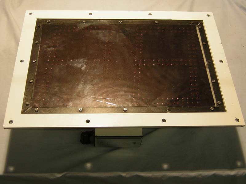
Click to zoom
Application Details
- Equipment Class
- FDS - Part 15 Field Disturbance Sensor
- Date of Grant
- Nov 06, 2005
- Application Purpose
- Original Equipment
- Date of Application
- Nov 06, 2005
- Equipment Note
- Vehicle Speed Sensor
- Frequency Range
- 24125.00000000 - 24125.00000000
- Company
- Radarsign LLC
- Country
- United States
Documents & Files
Document Text
Text extracted from the exhibit documents filed with the FCC. Open a document above to read the original.
Users Manual
Model TC-500S Guide to Operations (revised 9-25-05) www.radarsign.com Copyright 2005 RadarSign LLC. All Rights reserved radarsign TC-500S 2 I. Introduction 1. About Radarsign LLC 2. “MUST” items to review 3. Powering up the first time II. Getting Started – Basic Settings 1. PDA Start-up 2. Radarsign Software Start-up 3. Basic Settings 4. Sign and Software Start-up 5. Display Options 6. Speed Settings 7. Timer Operation 8. Turning Off the Radarsign 9. LED Settings and Blinkey III. Beam Settings 1. Sending settings from PDA to Sign 2. Receiving settings from Sign to PDA IV. Traffic Data - StreetSmart™ Software (Optional) 1. Retrieving Daily Records 2. Daily Statistics Report 3. Daily Time Records 4. Daily Speed Records 5. Retrieving Weekly Summary 6. Spreadsheet Template for Graphs V. Diagnostics 1. LED Tests 2. Battery and Solar Details 3. Sign History and Information VI. Pole Selection & Mounting Guidelines 1. Types of Poles 2. Location of installation 3. Mounting Hardware Appendix A: Data saved in your TC-500S sign Appendix B: System Specifications radarsign TC-500S 3 Thank you for your purchase of this Radarsign™ product. CAUTION: The RadarSign TC-500 series devices comply with Part 15 of the United States Federal Communication Commission (FCC) part 15 rules as shipped from the factory. The RadarSign device must not be opened or modified with the exception of the connection of the solar panel or AC power connections. Any changes or modifications not expressly approved by RadarSign LLC may void the users authority to operate the equipment under FCC rules. This device complies with part 15 of the FCC Rules. Operation is subject to the following two conditions: (1) This device may not cause harmful interference, and (2) this device must accept any interference received, including interference that may cause undesired operation. I. Introduction 1. We at Radarsign LLC, want your use and association with our products to be an enjoyable one. We have worked dillegently to design and build products with the features and durability that will last for years and exceed your expectations. If we have missed a feature, or you detect anything that is not to your liking, please let us know. We will strive to include your suggestions for improvement into our future designs. ! ! SPECIAL NOTICE ! ! 2. These are key considerations that MUST be addressed BEFORE you place the TC- 500S into operation. • CALL BEFORE YOU DIG!!! It is imperative that you are sure there are no buried utilities in the area you choose for pole mounting the Radarsign. Fines and cost of repairs vary by jurisdiction, and can be quite expensive. radarsign TC-500S 4 • For public roads, secure written permission with the local city or county traffic officials BEFORE putting your sign into operation. The right of way for most public roads is owned by the local government, and they have the right to remove ANY item not approved prior to installation. Radarsign representatives can assist you in this process. • Choose a pole for mounting the TC-500S that has a break-away base mounting system. This type of pole mounting system is available from many manufacturers, including Radarsign. Generally the poles are 3.5” to 4.5” round, U-Channel (or Hat Channel), decorative design, or 2” square. U-Channel and 2” square poles should be used in pairs to support the TC-500S, as the unit weighs between about 48 pounds. With high wind gusts, a single pole that is not sturdy enough will simply bend over, leaving the system ineffective. The break-away base is critical for reducing vehicle damage and passenger injury should the pole be struck by a moving vehicle that has left the road. RadarSign, Inc. reserves the right to change the specifications without notice. Contact our sales department for special applications and configurations. www.radarsign.com © 2005 RadarSign LLC. radarsign TC-500S 5 Power Connections 3. POWERING UP THE FIRST TIME A. Locate the open box at bottom of Radarsign B. Connect 4 prong male (yellow) and female pins to power up the TC-500S model with batteries. C. Watch LEDs run through quick test. (15-20 seconds) D. Connect 8 foot lead from solar panel, through Power Conduit Connection, to 2 prong solar connector. E. Proceed to software setup with PDA. Å AC or Solar Power Connector (2 prong) Power Conduit Connection Æ 4 Prong Internal Power Connection Æ radarsign TC-500S 6 II. Getting Started With every TC-500S, a Model IIIxe PDA is included. This device contains the software with menu driven screens to set up your Radarsign. It is the only model guaranteed to work with our Model TC-500S or TC-500A products. Here are the basic steps to activate your sign: 1. PDA START-UP A. PDA has two installed AAA batteries. Battery life is monitored by battery icon at top of main screen. Radarsign settings will remain intact in PDA while changing batteries, AS LONG AS YOU COMPLETE THE TASK IN LESS THAN ONE MINUTE ! B. Turn on the PDA with the lower left green button. C. To use backlight feature at night, hold the green on/off button down for 2 seconds. To turn off the backlight, repeat the process. D. Locate stylus pen in the back of the PDA. Use to tap the touch-screen program buttons. E. Locate ‘screen contrast’ wheel on back side of PDA. Rotate wheel for optimum viewing. F. Set PDA date and time by tapping <PREFS> on PDA main menu. Change date and time by tapping on item you wish to change. When completed tap the PDA home icon (lower left corner of screen, looks like a house). Battery level icon ON/OFF Button radarsign TC-500S 7 2. RADARSIGN SOFTWARE START-UP A. Tap the Radarsign icon once to go to setup menu. Wait 10-12 seconds for startup. Your TC-500S has a unique Serial number assigned to it. To access the main enu, you must first store this serial number in the Palm. Using the Palm’s number pad, enter your sign’s serial number. When finished, tape DONE. Now tap the PASSWORD line so the cursor shows blinking. Enter a password of your own choosi…
Text truncated - open the document above for the full version.
External Photos
FCC ID: TAU-TC-500 WO: EF0728-1 Company: RadarSign LLC Front of the chassis showing the display Rear of the chassis also showing the bottom side. FCC ID: TAU-TC-500 WO: EF0728-1 Company: RadarSign LLC Rear of the chassis also showing the top. Right side of the chassis FCC ID: TAU-TC-500 WO: EF0728-1 Company: RadarSign LLC Left side of the chassis Side of the horn antenna FCC ID: TAU-TC-500 WO: EF0728-1 Company: RadarSign LLC Front of the horn antenna Rear of the horn antenna
ID Label/Location Info
FCC ID: TAU-TC-500 This device complies with part 15 of the FCC Rules. Operation is subject to the following two conditions: (1) This device may not cause harmful interference, and (2) this device must accept any interference received, including interference that may cause undesired operation. radarsign tm Model TC-500A SNTC500A00001 www.radarsign.com 㔀 (特) 㜵 㤵 剡摡牓楧渠䙃䌠䍯浰汩慮捥⁌慢敬敶ⴴ 呵敳摡礬⁎潶敭扥爠〱Ⱐ(日)〵‵‵‵㨳(呼)(特)⁁䴀 4-90 Rev. 10/99 5095 Performance Resin Thermal Transfer Ribbon Description: Our performance resin ribbon formulation that produces images resistant to most harsh environments: smearing, moisture, abrasion, extreme temperature and chemicals when printed on Zebra’s synthetic label and tag materials. The low energy requirements for this ribbon will allow for excellent print quality even on some Zebra paper labels. UL Recognized and CSA Accepting Printing Systems with the following materials: • Z-Ultimate ® 3000 White•Z-Xtreme 3000 White™ • Z-Ultimate ® 3000 Silver•Z-Xtreme 3000 Silver™ • Z-Ultimate ® Select 3000 White (UL Only)•Z-Xtreme 4000 White™ • Z-Ultimate ® Select 3000 Silver (UL Only)•Z-Xtreme 3000 White™ •Z-Ultimate ® 3000 Color Suggested Applications: • Labels which are repetitively wand-scanned • Labels subject to abrasion or friction • Shelf and scan-pallet labels • Outdoor labeling applications in extreme environments • Chemical container labels • Labels exposed to water, alkali or acid solutions Technical Specifications 5095 Performance ColorBlack Ink FormulationResin Base FilmPolyester Base Film Caliper4.5 microns Scanning CapabilitiesIR and Visible Light Ribbon Length(s) / Inner Core Width(s)450m (1476 ft.) /25.4mm (1.0”) OR 91m (298 ft.) / 12.7mm (0.5”) Stocked Widths (450m Length)40, 60, 83, 89, 110, 131, 154, 174, 220mm (1.57”, 2.36”, 3.27”, 3.50”, 4.33”, 5.16”, 6.06”, 6.85”, 8.66”) Stocked Widths (91m length)64, 84, 110mm (2.52”, 3.31”, 4.33”) Recommended Storage Conditions:23°F to 104°F (-5°C to 40°C) at 20% to 85% RH 2-564 10/00 Z-Endure 3000 White ™ Thermal Transfer Material Description: Z-Endure 3000 White is a 2.0 mil thermal transfer printable acrylic label. The special acrylic film and high performance acrylic adhesive offer 10-year outdoor durability. This product will endure long-term outdoor weathering. Excellent print quality when combined with Zebra’s resin ribbons. Suggested ApplicationsSuggested Contacts • Vending machines•Department Managers • Utility meters•Production Manager • Outdoor tools/equipment•Using Departments Technical Specifications DescriptionCaliper FacestockTop-coated, white acrylic2.0 mil AdhesiveHigh performance acrylic adhesive0.8 mil Liner50 lb. semi-bleached kraft3.2 mil Total6.0 mil Recommended Zebra Ribbons:4100, 5095, 5100 Minimum Application Temperature:50°F (10°C) Service Temperature Range:-40°F to 302°F (-40°C to 150°C) Recommended Storage Conditions:32°F to 70°F (0°C to 21°C) at 35% to 50% RH Note: All products should be pre-tested to ensure that they meet all intended requirements of specific end-use applications. For testing of this material please order SAM5827. 4-90 Rev. 10/99 5095 Bar Code Scannability The below scannability testing was performed on Z4000, 140Xi, 140XiII, 90XiII, 170Xi, 105S, and Stripe 500. Label FacestockPrint SpeedBar CodeLab Results Coated Paper Labels and TagsUp to 4 ips10 mil normal codeTypical ANSI Grade A SyntheticsUp to 6 ips10 mil normal codeTypical ANSI Grade A Coated Paper Labels and TagsUp to 4 ips15 mil rotated codeTypical ANSI Grade B SyntheticsUp to 6 ips15 mil rotated codeTypical ANSI Grade B 5095 Performance Analysis All of the below tests were performed using 10 cycles (20 rubs) with the crockmeter. Test SolventsZ-Ultimate ® 3000 WhiteZ-Xtreme™ 4000 White Glass Cleaner w/Ammonia ** Formula 409* ** Skydrol* Motor Oil ** Brake Fluid4 Gunk Degreaser* ** WD-40* ** Genesolv* Rho-Tron*4 Hexane ** Xylene Gasoline4 4 Acetone Alcohol (90% Isopropyl Alcohol) ** *Trademarks of the respective companies. * Scanning receives a “B” ANSI grade or better 4 Scanning receives a “F” ANSI grade or better o Barcode does not scan All products should be pre-tested to ensure it meets all intended requirements of specific end-use applications. For testing of this product, please order sample ribbon 4100BK08005.
Internal Photos
FCC ID: TAU-TC-500 WO: EF0728-1 Company: RadarSign LLC Rear of the display PCB with CPU board and Gunnplexer attached. Front of the display PCB showing the leds FCC ID: TAU-TC-500 WO: EF0728-1 Company: RadarSign LLC Rear of the display PCB Top of the CPU PCB FCC ID: TAU-TC-500 WO: EF0728-1 Company: RadarSign LLC Bottom of the CPU PCB Top of power supply with heatsink attached FCC ID: TAU-TC-500 WO: EF0728-1 Company: RadarSign LLC Top of power supply with heatsink removed Bottom of the power supply FCC ID: TAU-TC-500 WO: EF0728-1 Company: RadarSign LLC Top of FE-17 board Bottom of FE-17 board FCC ID: TAU-TC-500 WO: EF0728-1 Company: RadarSign LLC View of the FE-17 board with cable connected to the Gunnplexer Another view of the FE-17 board connected to the gunnplexer FCC ID: TAU-TC-500 WO: EF0728-1 Company: RadarSign LLC Bottom of Gunnplexer board Side of the Gunnplexer FCC ID: TAU-TC-500 WO: EF0728-1 Company: RadarSign LLC Front of the Gunnplexer Side of the Gunnplexer FCC ID: TAU-TC-500 WO: EF0728-1 Company: RadarSign LLC Back of the Gunnplexer Top of the Gunnplexer
Parts List/Tune Up Info
GAIN dB 3dB width E/H deg. Length cm Width cm (H) Height cm (E) MDT86552 16 20/27 4.3 4.6 3.5 MDT6366 12 34/47 1.3 3.1 2.3 MDT6386 17 17/26 4.9 4.2 3.5 Features •For high and low gain applications •Die cast •Priced for Commercial Applications K-band antennas MDT 86552, 6386 & 6366 Description MDT die cast K-band horn antennas are designed to be easily integrated into low cost, commercial sensor applications. Providing a variety of gains and beam patterns these horns are available from stock as a cost effective alternative to custom tooled horns. Ordering Information All antennas have individual draw- ings available by request. Please confirm requirements for harmonic filters at time of order. MDT 6366 MDT 6386 MDT 86552 February 2004 WIDTH (H) HIGHT (E) L E N G T H Note: MDT6386 has an integrated harmonic filter
Test Report
Test Report Report No EF0728-1 Client RadarSign LLC Phone 678-491-4734 Fax none FRN 0012097002 Models TC-500 FCC ID TAU-TC-500 Curtis-Straus LLC is accredited by the American Association for Laboratory Accreditation for the specific scope of accreditation under Certificate Number 1627-01. This report may contain data which is not covered by the A2LA accreditation. _____________________________________________________________ Curtis-Straus Equipment Type Field Disturbance Sensor Equipment Code FDS Results As detailed within this report Prepared by Josh LeBlanc – Test Engineer Authorized by Michael Buchholz – EMC Manager Issue Date 10/17/05 Conditions of issue This Test Report is issued subject to the conditions stated in ‘terms and conditions’ section of this LLC • 527 Great Road • Littleton, MA • TEL (978) 486-8880 • FAX (978) 486-8828 REPORT: EF0728-1 FCC ID: TAU-TC-500 RadarSign LLC _____________________________________________________________ Summary...........................................................................................................3 Test Methodology..............................................................................................3 EUT Configuration.............................................................................................4 Statement of Conformity....................................................................................5 Harmonic & Spurious Radiated Emissions........................................................6 Fundamental Field Strength..............................................................................8 Voltage Variations.............................................................................................9 AC Line Conducted Emission Measurements.................................................11 Test Equipment Used......................................................................................12 Terms And Conditions.....................................................................................13 A2LA Accreditation..........................................................................................15 LLC • 527 Great Road • Littleton, MA • TEL (978) 486-8880 • FAX (978) 486-8828 Page 2 of 17 Curtis-Straus REPORT: EF0728-1 FCC ID: TAU-TC-500 RadarSign LLC _____________________________________________________________ Summary This report is an application for certification of a transmitter operating pursuant to 47 CFR 15.245 provided for the operation in the band of 24075 - 24175 MHz. The product covered by this report is the TC-500. It is a self-contained radar system for outdoor use. It utilizes a gunn transceiver manufactured by Microwave Device Technology Corporation model number MO9062 operating in a CW mode at 24125 MHz with a frequency tolerance of ±5 MHz. Its intended application is the display of vehicle speed and the recording of traffic count and speed. A detailed description of the antenna is provided in the antenna exhibit. Test Methodology Radiated emission testing was performed according to the procedures specified in ANSI C63.4 (2003). The EUT was maximized around the vertical axis as this is the only orientation it can be installed. The antenna is internal and cannot be maximized separately. The EUT can be powered by 100-240Vac, or via a connection to a solar panel. The EUT was tested utilizing 120Vac as a worst case scenario as it has additional AC to DC circuitry and a mains connection. The ambient environmental conditions were as follows: Date Temperature Humidity 10/10/05 23.7°C 47% 10/11/05 23.7°C 48% Frequency range investigated: 30 MHz- 100GHz Measurement Distance: Frequency (MHz) Distance (m) Comments AC conducted 0.15 – 30MHz - Conducted Fundamental 24125 MHz 3 m Radiated Spurious & harmonics 30MHz - 100GHz 3 m Radiated All readings below 1GHz are quasi-peak. All readings above 1GHz are peak. LLC • 527 Great Road • Littleton, MA • TEL (978) 486-8880 • FAX (978) 486-8828 Page 3 of 17 Curtis-Straus REPORT: EF0728-1 FCC ID: TAU-TC-500 RadarSign LLC _____________________________________________________________ EUT Configuration EUT Configuration Work Order: F0728 Company: Radar Sign Company Address: 3284 Medlock Bridge Road, Suite 100 Norcross, GA 30092 Contact: Ken Bass MNSN EUT: TC-500Test Sample 1 EUT Description: Vehicle traffic feedback system utilizing K-band radar. It uses a gunn transceiver manufactured by Microwave Device Technology Corporation model number MO9062 operating in a CW mode. EUT Max Fre quency: 24.125GHz Support Equipment: MNSN none EUT Cables: QtyShielded?LengthFerrites AC power1no1.5mnone Unpopulated EUT Ports: QtyReason none Software / Operating Mode Description: The EUT was transmitting and receiving. LLC • 527 Great Road • Littleton, MA • TEL (978) 486-8880 • FAX (978) 486-8828 Page 4 of 17 Curtis-Straus REPORT: EF0728-1 FCC ID: TAU-TC-500 RadarSign LLC _____________________________________________________________ Statement of Conformity The TC-500 has been found to conform to the following parts of the 47 CFR, as detailed below: 47 CFR Part # Comments 15.15(b) The product contains no user accessible controls that increase transmission power above allowable levels. 15.19 The label is shown in the label exhibit. 15.21 Information to the user is shown in the instruction manual exhibit. 15.27 No special accessories are required for compliance. 15.31(e) The voltage was varied to ±15% of the rated voltage. 15.203 The device does not have an external antenna port. 15.204 See the antenna exhibit for a description of the antenna. 15.205 15.209 The fundamental is not in a restricted band and the spurious emissions in the restricted bands comply with the general emission limits of 15.209. 15.207 Product complies with AC line conducted emissions limits. 15.245(a) The device is a field disturbance sensor. 15.245(b) The device meets the field strength limit of 2500mV/m (128dBμV/m) at the fundamental. 15.245(b)(1) The device meets the field strength lim…
Text truncated - open the document above for the full version.
Test Setup Photos
FCC ID: TAU-TC-500 WO: EF0728-1 Company: RadarSign LLC Fundamental, Harmonic and Spurious Radiated Emissions - Front Fundamental, Harmonic and Spurious Radiated Emissions Rear FCC ID: TAU-TC-500 WO: EF0728-1 Company: RadarSign LLC AC line Conducted Emissions Voltage Variations
Contact Information
Applicant
Charles Barry Ward(VP Technology)
Test Firm
BUREAU VERITAS CONSUMER PRODUCTS SERVICES, INC.Ozgur Ozturk
[email protected]978-486-8880
Technical Specifications
| # | Rule Parts | Frequency Range | Power Output |
|---|---|---|---|
| 1 | 15.245 | 24.13 GHz - 24.13 GHz | - |