TAW-AVIR2500R2.4GHz Wireless A/V Sender
Yuanfann International Co., Ltd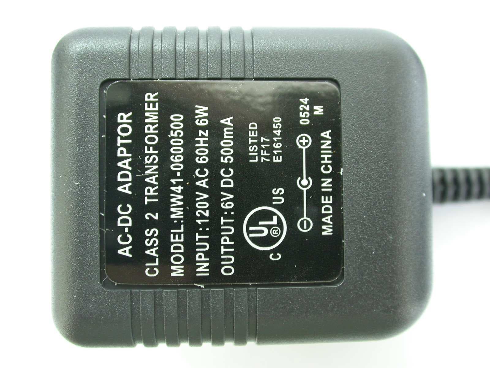
Click to zoom
Application Details
- Equipment Class
- DSC - Part 15 Security/Remote Control Transmitter
- Date of Grant
- Jul 13, 2005
- Application Purpose
- Original Equipment
- Date of Application
- Jul 13, 2005
- Equipment Note
- 2.4GHz Wireless A/V Sender
- Frequency Range
- 433.92000000 - 433.92000000
- Country
- Taiwan
Documents & Files
Document Text
Text extracted from the exhibit documents filed with the FCC. Open a document above to read the original.
Users Manual
2.4GHz Wireless Audio/Video Sender User Manual 1 Package Contents • Transmitter x 1 • Receiver x 1 • Infrared (IR) eye cable x 1 • Remote antenna x 1 • Audio/Video cable x 2 • Power adaptors (DC6V) x 2 • User manual x 1 Note: The transmitter and the receiver look very similar. You can find “transmitter” and “receiver” labels on the side of the units. See Fig. 1. Product Layout Transmitter/Receiver (See Fig. 2 and Fig. 3) 1. Power/Channel Indicator 2. IR Window 3. Channel Select Button (Select the channel by pressing the tact switch to the channel number you want. Select the same channel both on the transmitter and the receiver). 4. Audio Jack (Red) 5. Audio Jack (White) 6. Video Jack (Yellow) 7. Power On/Off 8. Power Adaptor Plug 9. IR Eye (Transmitter) / Antenna(Receiver) Fig. 1 TransmitterReceiver ReceiverTransmitter 2 Setting Up Before you make the connection: • Set the channel by pressing the select button on the front of the transmitter and the receiver to the same channel. 1. Setting up the Transmitter 1.1 Connect the Transmitter to an A/V Component A/V Connection Connect the mini-plug of the provided A/V cables to the A/V jack on the rear of the transmitter; connect the other end of the cables to the A/V Fig. 2 1 2 3 4 5 6 7 Receiver/Transmitter ReceiverTransmitter 4 6 7 8 9 Fig. 3 8 9 5 3 jacks (or Scart connector) of the A/V component labeled LINE OUT. See Fig. 4. RF Connection – for A/V Component without Spare A/V Output Jacks If your A/V component has only one set of A/V output jacks, and you want to use it with a nearby TV, connect coaxial cable from the signal OUT port on the A/V component to the VHF/UHF IN port on your TV. In order to also view cable transmission on that TV, connect your incoming cable TV source to the single IN port of the A/V component. Please see Fig. 5. Transmitter VIDEOAUDIO A/V Cable Satellite receiver/DVD/VCD Fig. 4 OUT VHF/UHF RF OUT VIDEO AUDIO IN Transmitter A/V Component TV Fig. 5
Users Manual
4 Note 1: On a NTSC system, the connector on the A/V equipment is an RCA jack. Connect the yellow plug to the jack labeled VIDEO, the red plug to the jack labeled AUDIO RIGHT and the white plug to the jack labeled AUDIO LEFT. Note 2: On a PAL system, connect the Scart connector labeled TRANSMITTER to the Scart connector labeled OUT on the A/V equipment. Note 3: If the A/V equipment has only one output for audio (mono sound only), connect the white plug to that single audio output jack. 1.2 Power Supply a. Plug one end of the provided power adaptor into a wall outlet and the other end into the rear of the transmitter. See Fig. 6. b. Turn on the transmitter. The LED on the front of the unit should light up. 2. Setting up the Receiver 2.1 Connect the Receiver to a TV A/V Connect – for TV with A/V Input Jacks Connect the mini-plug of the provided A/V cables to the A/V jack on the rear of the receiver; connect the other end of the cable to the A/V jacks (or Scart connector) on the TV labeled LINE IN. See Fig. 7. POW ER ON-OFF Transmitter Fig. 6 Wall Outlet 5 RF Connection – for TV without A/V Input Jacks If there is no A/V input jacks on your TV, you will need to get an RF modulator (available at your local electronics store) to make the connection between TV and receiver. See Fig. 8. Connection through an A/V Component If an A/V component (VCR, DVD player, DBS receiver, and etc.) is connected to the TV already, you can just connect the receiver to the free LINE IN jacks on the A/V component. See Fig. 9. TV VIDEOAUDIO IN ReceiverA/V Cable Fig. 7 Fig. 8 VHF/UHF TV RF OUT RF Modulator CH 3/4 VIDEO AUDIO IN Receiver A/V Cable 6 Note 1: Connect the yellow plug to the jack labeled VIDEO, the red plug to the jack labeled AUDIO RIGHT and the white plug to the jack labeled AUDIO LEFT. Note 2: If the TV has only one input for audio (mono sound only), connect the white plug to that single audio in jack. 2.2 Connecting the Remote Antenna a. Connect the provided remote antenna with the receiver by plugging it in the hole labeled Ant. on the receiver. b. If possible, make the antenna straight. Do not bend the antenna. See Fig. 10. 2.3 Power Supply a. Plug one end of the provided power adaptor into a wall outlet and Fig. 9 VHF/UHF RF OUT VIDEO AUDIO IN Receiver A/V Cable A/V Component TV Fig. 10 Remote Antenna Receiver 7 the other end into the rear of the receiver. See Fig. 11. b. Turn on the receiver. The LED on the front of the unit should light up. Other Applications Using Remote Control The Wireless A/V Sender gives you the ability to control A/V components from another room using your existing remote control device. To use this function, follow the steps below: 1. Place the transmitter next/close to the A/V source component and plug the IR eye into the jack located on the rear of the transmitter (IR Eye plug). Adhere the IR eye directly to the IR window on the front of the source component (see Fig. 12) OR place the IR eye in front of the source component (see Fig. 13). Fig. 11 Wall Outlet Fig. 12 Receiver POW ER ON-OFF Receiver TV Remote Control AV Source Component Transmitter IR Eye Fig. 13 AV Source Component 8 2. Position the receiver so that your remote control signal can strike the IR window on the front of the receiver. Set the remote antenna on the receiver straight. Do not bend the remote antenna. 3. To use your remote control, point it at the front of the receiver and operate it as you normally would. Specifications Transmitter/Receiver A/V Transmitting Frequency2.4GHz IR Extender Frequency433.92MHz A/V Signal Range100 meters (300 feet) clear line of sight IR Extender Range70 meters (200 feet) clear line of sight AntennaBuilt-in antenna Channel4 selectable channels AudioStereo audio input and output VideoComposite input and output Dimensions12.5 x 8 x 2.5 (cm) for transmitter/receiver Weight125g for transmitter/receiver PowerDC6V, 500mA Operating Temperature0 ~ 40 (32 ~ 104 )°C °C °C °C Providing the latest technologies to our customers is our responsibility; therefore, we reserve the right to change the specifications without prior notice. Trouble Shooting If you are not getting any signal at all • Check that the transmitter and receiver are properly connected to the A/V TV Remote Control Transmitter IR Eye Receiver 9 components from which you want to send/receive the A/V signal. • Make sure the transmitter and the receiver are turned on. • Check power switches on the remote TV and video source (VCR, DVD player, satellite receiver, etc). • Make sure power plugs are pushed all the way in. • Check all cable connections. • Check the CHANNEL switch on both transmitter and receiver are set to the same number. • If you connect the receiver to a TV through an RF modulator, check that the TV is tuned to the same channel as the TV Channel switch on the RF modulator (3 or 4). If the signal is poor, or there is interference • Adjust the transmitter by rotating orientations until you get the best reception. • Change the channel on both transmitter and receiver and make them the same. • If there is a microwave oven in use in the path between the transmitter and receiver, remove the microwave oven or turn it off. • Make sure the transmitter and receiver are within range of each other (range of approximately 300 feet; 100 meters in a clear line of sight). Care and Maintenance • Keep all its parts and accessories out of the reach of young children. • Do not attempt to open the case. Non-expert handling of the device may damage it. • Keep dry. Precipitation, humidity, and liquids, contain minerals that will corrode electronic circuits. • Do not use or store in dusty, dirty areas. Moving parts may be damaged. • Do not store in hot areas. High temperatures can shorten the life of electronic devices and warp or melt certain plastics. • Do not store in very cold areas. When the A/V sender warms up (to its normal temperature), moisture can form inside the case, which may damage electronic circuit boards. • Do no…
Text truncated - open the document above for the full version.
Cover Letter(s)
1 Helen Zhao Subject:FW: Yuanfann International Co., Ltd, FCC ID: TAW-AVIR2500R, Assessment NO.: AN05T4945, Notice#2 User Manual_02.pdf FCC ID Label RX_r.pdf Block Diagram.pdfSchematic.pdfOperation Descriptions.pdf Cover Letter.PDFConfidentiality request.PDF From: hsieh Sent: Thursday, July 14, 2005 12:38 AM To: Helen Zhao Subject: Re: Yuanfann International Co., Ltd, FCC ID: TAW-AVIR2500R, Assessment NO.: AN05T4945, Notice#2 Dear Helen, Re-Q#1: Attached please find the Block Diagram, FCC ID label format, Operational Description, Schematics, Cover Letter and Confidentiality Letter. Re-Q#2: Yes. During this test, we use an IR remote controller (ex: DVD or VCR remote control) to produce an IR signal to IR sensor (EUT). The word "being released" means to release the bottom of IR remote controller. Thanks for your help. Best regards, Joe Hsieh -----Original Message----- From: Compliance Certification Services [mailto:[email protected]] Sent: Wednesday, July 13, 2005 11:32 AM To: Helen Zhao Subject: Yuanfann International Co., Ltd, FCC ID: TAW-AVIR2500R, Assessment NO.: AN05T4945, Notice#2 Question #1: Please submit Block Diagram, FCC ID label format, Operational Description, Schematics, Agent authorization Letter, Confidentiality Letter. Please make sure Block Diagram includes 433MHz TX portion. Please make sure FCC ID label format contains FCC15.19 labeling requirement. Question #2: This device is activated automatically upon receiving an IR signal. Please explain why the test report section 6.2 said "The transmitter is operated by manual and active time is 0.223s after being released." Please explain if any support equipment was ever used. Best Regards, Helen Zhao 2 The items indicated above must be submitted before processing can continue on the above referenced application. Failure to provide the requested information within 30 days of the original e-mail date may result in application dismissal and forfeiture of the filing fee. Also, please note that partial responses increase processing time and should not be submitted. Any questions about the content of this correspondence should be directed to the e-mail address listed below the name of the sender.
External Photos
ETC Report No.: ET94S-05-102-02 Page A1 of A2 FCC ID:TAW-AVIR2500R ANNEX A: EXTERNAL CONSTRUCTION PHOTOS OF EUT 1. Outside view 1 of EUT 2. Outside view 2 of EUT ETC Report No.: ET94S-05-102-02 Page A2 of A2 FCC ID:TAW-AVIR2500R 3. adapter
ID Label/Location Info
FCC ID Label & Location This device complies with Part 15 of the FCC Rules. Operation is subject to the following two conditions: (1) this device may not cause harmful interference, and (2) this device must accept any interference received, including interference that may cause undesired operation.
Internal Photos
ETC Report No.: ET94S-05-102-02 Page B1 of B6 FCC ID:TAW-AVIR2500R ANNEX B: INTERNAL CONSTRUCTION PHOTOS OF EUT 1. Inside View 1 of EUT 2. Inside View 2 of EUT ETC Report No.: ET94S-05-102-02 Page B2 of B6 FCC ID:TAW-AVIR2500R 3. Inside View 3 of EUT 4. Inside View 4 of EUT ETC Report No.: ET94S-05-102-02 Page B3 of B6 FCC ID:TAW-AVIR2500R 5. Inside View 5 of EUT 6. antenna ETC Report No.: ET94S-05-102-02 Page B4 of B6 FCC ID:TAW-AVIR2500R 7. Front view of PCB1 8. Rear view of PCB1 ETC Report No.: ET94S-05-102-02 Page B5 of B6 FCC ID:TAW-AVIR2500R 9. Front view of PCB2 10. Rear view of PCB2 ETC Report No.: ET94S-05-102-02 Page B6 of B6 FCC ID:TAW-AVIR2500R 11. Front view of PCB3 12. Rear view of PCB3
Test Report
ETC Report No. : ET94S-05-102-02 Sheet 1 of 25 Sheets FCC ID:TAW-AVIR2500R Rev. No 1.0 CONFORMANCE TEST REPORT FOR FCC 47 CFR, Part 15 Subpart C Report No.: ET94S-05-102-02 Client: Yuanfann International Co., Ltd. Product: 2.4GHz Wireless A/V Sender Model: AVIR-2500 FCC ID: TAW-AVIR2500R Manufacturer/supplier: Yuanfann International Co., Ltd. Date test item received: 2005/05/12 Date test campaign completed: 2005/06/21 Date of issue: 2005/07/11 The test result only corresponds to the tested sample. It is not permitted to copy this report, in part or in full, without the permission of the test laboratory. Total number of pages of this test report: 25 pages Total number of pages of photos: External photos 2 pages Internal photos 6 pages Setup photos 2 pages Test Engineer Checked By Approved By Jeng De Hsu Mark Joe Hsieh ELECTRONICS TESTING CENTER, TAIWAN NO.8, LANE 29, WENMING RD., LESHAN TSUEN, GUISHAN SHIANG, TAOYUAN COUNTY, TAIWAN 33382, R.O.C. TEL: (03) 3276170~4 INT: +886-3-3276170~4 FAX: (03) 3276188 INT: +886-3-3276188 ETC Report No. : ET94S-05-102-02 Sheet 2 of 25 Sheets FCC ID:TAW-AVIR2500R Rev. No 1.0 TEST REPORT CERTIFICATION Client : Yuanfann International Co., Ltd. Address : 9F, No. 515, Jhong Jheng Rd., Jhong He, Taipei County 235, Taiwan, R.O.C. Manufacturer : Yuanfann International Co., Ltd. Address : 9F, No. 515, Jhong Jheng Rd., Jhong He, Taipei County 235, Taiwan, R.O.C. EUT : 2.4GHz Wireless A/V Sender Trade name : ---- Model No. : AVIR-2500 Power Source : Adapter Model No.: MW41-0600500 Input: 120Vac, 60Hz, 6W Output: DC 6Vdc, 500mA Regulations applied : FCC 47 CFR, Part 15 Subpart C (2004) The testing described in this report has been carried out to the best of our knowledge and ability, and our responsibility is limited to the exercise of reasonable care. This certification is not intended to believe the sellers from their legal and/or contractual obligations. The compliance test is only certified for the test equipment and the results of the testing report relate only to the item tested. The compliance test of this report was conducted in accordance with the appropriate standards. It’s not intention to assure the quality and performance of the product. This report shall not be reproduced except in full, without the approval of ETC. This report must not be used by the client to claim product endorsement by NVLAP or any agency of the U.S. Government. Laboratory Introduction: Electronics Testing Center, Taiwan is recognized, filed and mutual recognition arrangement as following: 1 ISO9001: TüV Product Service 2 ISO/IEC 17025: BSMI, CNLA, DGT, NVLAP, CCIBLAC, UL, Compliance 3 Filing: FCC, Industry Canada, VCCI 4 MRA: Australia, Hong Kong, New Zealand, Singapore, USA, Japan, Korea, China, APLAC through CNLA 5 FCC Registration Number: 90588, 91094, 91095 NVLAP Lab Code 200133-0 ETC Report No. : ET94S-05-102-02 Sheet 3 of 25 Sheets FCC ID:TAW-AVIR2500R Rev. No 1.0 Table of Contents Page 1. GENERAL INFORMATION ......................................................................................................................................4 1.1 P RODUCT D ESCRIPTION .................................................................................................................................................4 1.2 C HARACTERISTICS OF D EVICE :......................................................................................................................................4 1.3 T EST M ETHODOLOGY ....................................................................................................................................................4 1.4 T EST F ACILITY ...............................................................................................................................................................4 2. DEFINITION AND LIMITS........................................................................................................................................5 2.1 D EFINITION ....................................................................................................................................................................5 2.2 RESTRICTED BANDS OF OPERATION...............................................................................................................................5 2.3 LIMITATION....................................................................................................................................................................6 2.4 L ABELING R EQUIREMENT ..............................................................................................................................................7 2.5 U SER I NFORMATION .......................................................................................................................................................7 3. RADIATED EMISSION MEASUREMENT..............................................................................................................8 3.1 A PPLICABLE S TANDARD .................................................................................................................................................8 3.2 M EASUREMENT P ROCEDURE .........................................................................................................................................8 3.3 T EST D ATA ..................................................................................................................................................................10 3.4 FIELD STRENGTH CALCULATION..................................................................................................................................12 3.5 RADIATED TEST EQUIPMENT.......................................................................................................................................12 3.6 M EASURING I NSTRUMENT S ETUP .................................................................................................................................16…
Text truncated - open the document above for the full version.
Test Setup Photos
ETC Report No. : ET94S-05-102-02 Sheet 1 of 2 Sheets FCC ID:TAW-AVIR2500R Photos of Radiation Measuring Setup ETC Report No. : ET94S-05-102-02 Sheet 2 of 2 Sheets FCC ID:TAW-AVIR2500R Photos of Conduction Measuring Setup
Contact Information
Applicant
Huei-tsen Lee(President)
Test Firm
Electronics Testing Center, TaiwanWin-Po Tsai
Technical Specifications
| # | Rule Parts | Frequency Range | Power Output |
|---|---|---|---|
| 1 | 15.231 | 433.92 MHz - 433.92 MHz | - |
Other Applications from Yuanfann International Co., Ltd

TAW-AVIR2500T
Jul 13, 20052.4GHz Wireless A/V Sender
Equipment Class
DXX - Part 15 Low Power Communication Device Transmitter