TB6-8XXBluetooth Headset
Perfect Tech Co ., Ltd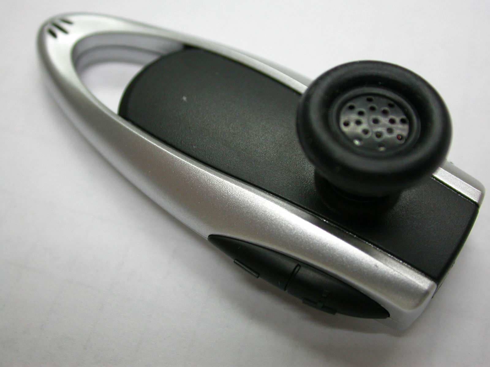
Click to zoom
Application Details
- Equipment Class
- DSS - Part 15 Spread Spectrum Transmitter
- Date of Grant
- Jun 21, 2005
- Application Purpose
- Original Equipment
- Date of Application
- Jun 21, 2005
- Equipment Note
- Bluetooth Headset
- Frequency Range
- 2402.00000000 - 2480.00000000
- Company
- Perfect Tech Co ., Ltd
- Country
- Taiwan
Documents & Files
Document Text
Text extracted from the exhibit documents filed with the FCC. Open a document above to read the original.
Users Manual
ENGLISH Introduction Bluetooth Headset The Bluetooth Headset is a Bluetooth device developed with the latest Bluetooth technology, which can connect to other Bluetooth devices such as mobile phone, desktop or notebook computer, PDA (with audio gateway profile supported) wirelessly within a range of 10 meters. Box Content - Bluetooth Boom headset - Travel charger 100/240V - User Manual - Necklace and earhook. Description: Volume down volume up P P Answering call on/off Voice dialing pairing Redial end call Mute Getting Started Charging battery The Headset comes with an embedded rechargeable battery. For first time use, it takes about 3 hours to fully charge the battery. Afterwards, it takes about 2 hours to fully charge. With battery fully charged, the talk time is about 5 hours, and the stand-by time will be about 120 hours. 1. Connect Travel Charger with AC power; the indicator of charger will light up. 2. Connect the Charger to the on headset, red LED on headset will light up. 3. When the battery is full charged, the red indicator of Connector will be off. Turning On/Off Headset 1. To turn on the Headset, press and hold P (1) button for 2 seconds. The blue indicator of Headset flashes. 2. To turn off the Headset, press and hold P (1) button for 3 seconds. You will hear two low tones and the red indicator flashes quickly. Then the Headset is powered off. 3. The red indicator of Headset will flash slowly when battery low. Paring Headset You are required to pair the Headset with your mobile phone or other devices before using it. Step 1: The Headset must be powered off before initiating pairing. To initiate pairing, press a hold P (1) button for 4 seconds until the blue and red indicators of Headset are flashing alternatively. Step 2: Initiate pairing process of your mobile phone. Refer to the manual of mobile phone for detail process. You will see a new item” BT Headset” added in your Bluetooth device list after searching process. Step 3: You will be asked to enter pin-code to complete pairing, enter 1234 and confirm it. (Note: The 1234 is default pin-code pre-stored in Headset.) The red indicator of Headset will turn off and the blue indicator will flash slowly after pairing completed successfully. If no pairing is possible for a period of time (approx. two minutes), the Headset will automatically power off, and so the previous pairing (if any) is revoked. You may need to repeat steps 1 to 3 until pairing succeeds Making Calls You are able to use the Headset to make calls when it is paired successfully with your mobile phone. 1. Using voice dialing (please check your mobile phone instruction manual to see if this function is enabled) – Press P (2) button, waiting for a beep and say the name of the person you want to call. Press P (2) button again to cancel voice dialing. 2. Using phone keys – Dial the number on the mobile phone as you usually do. Once the call has been set up, the voice will be transmitted to Headset automatically. 3. Redial – Press and hold P (2) button for 3 seconds to redial the last number you called. Answering/Ending Calls 1. When the Headset is powered on and the mobile phone rings, you will hear a musical tone and the blue indicator will change to be quick flashing. Press P (2) button to answer the call. 2. End calls by pressing P (1) button. Adjust volume 3. Adjust Headset volume by pressing V (1) button for volume up and pressing or V (2) button for volume down. Mute function Press P (2) for a Mute function. Press again to disable the mute function Low Battery When the red indicator starts to flash, it indicates that the Headset is running low on battery. Charge the Headset for 2 hours until the red indicator turns off. NOTE: The changes or modifications not expressly approved by the party responsible for compliance could void the user’s authority to operate the equipment. To comply with the FCC RF exposure compliance requirements, this device and its antenna must not be co-located or operating to conjunction with any other antenna or transmitter. This device complies with Part 15 of the FCC Rules. Operation is subject to the following two conditions: (1) this device may not cause harmful interference, and (2) this device must accept any interference received, including interference that may cause undesired operation.
Cover Letter(s)
1 Helen Zhao Subject:FW: [score: -2] FW: PERFECT TECH CO ., LTD, FCC ID: TB6-8XX, Assessment NO.: AN05T4874, Notice#1 Importance:High Test Report_01.pdfTest Report_02.pdf From: hsieh Sent: Wednesday, June 22, 2005 2:38 AM To: Helen Zhao Subject: Re: [score: -2] FW: PERFECT TECH CO ., LTD, FCC ID: TB6-8XX, Assessment NO.: AN05T4874, Notice#1 Importance: High Dear Helen, Attached please find the test report. Re-Q#1 : After remove the notebook, the plots was agree with the data in the table. Re-Q#2 : Yes, the star mark "*" is the instable result. We have updated all of the plots with star mark (PPSD and dwell time). Thanks for your remind. Any more questions please feel free to contact with me. Best regards, Joe Hsieh -----Original Message----- From: Compliance Certification Services [mailto:[email protected]] Sent: Tuesday, June 21, 2005 3:57 PM To: Helen Zhao Subject: PERFECT TECH CO ., LTD, FCC ID: TB6-8XX, Assessment NO.: AN05T4874, Notice#1 Question #1: The radiated emission test data listed in the table do not agree with the plots provided in the same report. Please update the test report. Question #2: Some of PPSD plots and dwell time plots have red star mark ("*"). It seems the plots need to be stablized for a while, the plots were printed out a little bit earlier. Please confirm. Best Regards, Helen Zhao The items indicated above must be submitted before processing can continue on the above referenced application. Failure to provide the requested information within 30 days of the original e-mail date may result in 2 application dismissal and forfeiture of the filing fee. Also, please note that partial responses increase processing time and should not be submitted. Any questions about the content of this correspondence should be directed to the e-mail address listed below the name of the sender.
External Photos
ETC Report No.: ET94S-05-203 Page A1 of A1 FCC ID:TB6-8XX ANNEX A: EXTERNAL CONSTRUCTION PHOTOS OF EUT 1. Outside view 1 of EUT 2. Outside view 2 of EUT
ID Label/Location Info
FCC ID Label / Location FCC ID: TB6-8XX
Internal Photos
ETC Report No.: ET94S-05-203 Page B1 of B3 FCC ID: TB6-8XX ANNEX B: INTERNAL CONSTRUCTION PHOTOS OF EUT 1. Inside View of EUT 2. Adaptor ETC Report No.: ET94S-05-203 Page B2 of B3 FCC ID: TB6-8XX 3. Adaptor 4. Adaptor ETC Report No.: ET94S-05-203 Page B3 of B3 FCC ID: TB6-8XX 5. Front view of PCB 6. Rear view of PCB
Test Report
ETC Report No. : ET94S-05-203 Sheet 1 of 79 Sheets FCC ID: TB6-8XX Rev. No 1.0 CONFORMANCE TEST REPORT FOR FCC 47 CFR, Part 15 Subpart C Report No.: ET94S-05-203 Client: PERFECT TECH CO ., LTD Product: Bluetooth Headset Model: 8XX FCC ID: TB6-8XX Manufacturer/supplier: PERFECT TECH CO ., LTD Date test item received: 2005/05/27 Date test campaign completed: 2005/06/15 Date of issue: 2005/06/16 The test result only corresponds to the tested sample. It is not permitted to copy this report, in part or in full, without the permission of the test laboratory. Total number of pages of this test report: 79 pages Total number of pages of photos: External photos 1 pages Internal photos 3 pages Setup photos 4 pages Test Engineer Checked By Approved By James Mark Joe Hsieh ELECTRONICS TESTING CENTER, TAIWAN NO.8, LANE 29, WENMING RD., LESHAN TSUEN, GUISHAN SHIANG, TAOYUAN COUNTY, TAIWAN 33382, R.O.C. TEL: (03) 3276170~4 INT: +886-3-3276170~4 FAX: (03) 3276188 INT: +886-3-3276188 ETC Report No. : ET94S-05-203 Sheet 2 of 79 Sheets FCC ID: TB6-8XX Rev. No 1.0 TEST REPORT CERTIFICATION Client : PERFECT TECH CO ., LTD Address : 3F.,No.9 Lane 175,Nankan Rd., Lujhu Township,Taoyuan County 338 ,Taiwan Manufacturer : PERFECT TECH CO ., LTD Address : 3F.,No.9 Lane 175,Nankan Rd., Lujhu Township,Taoyuan County 338 ,Taiwan EUT : Bluetooth Headset Trade name : perfect Model No. : 8XX Power Source : Adapter Input: 100-240Vac, 50/60Hz, 0.4A Output: DC 5.3Vdc ± 0.3, 600mA max Regulations applied : FCC 47 CFR, Part 15 Subpart C (2004) The testing described in this report has been carried out to the best of our knowledge and ability, and our responsibility is limited to the exercise of reasonable care. This certification is not intended to believe the sellers from their legal and/or contractual obligations. The compliance test is only certified for the test equipment and the results of the testing report relate only to the item tested. The compliance test of this report was conducted in accordance with the appropriate standards. It’s not intention to assure the quality and performance of the product. This report shall not be reproduced except in full, without the approval of ETC. This report must not be used by the client to claim product endorsement by NVLAP or any agency of the U.S. Government. Laboratory Introduction: Electronics Testing Center, Taiwan is recognized, filed and mutual recognition arrangement as following: 1 ISO9001: TüV Product Service 2 ISO/IEC 17025: BSMI, CNLA, DGT, NVLAP, CCIBLAC, UL, Compliance 3 Filing: FCC, Industry Canada, VCCI 4 MRA: Australia, Hong Kong, New Zealand, Singapore, USA, Japan, Korea, China, APLAC through CNLA 5 FCC Registration Number: 90588, 91094, 91095 NVLAP Lab Code 200133-0 ETC Report No. : ET94S-05-203 Sheet 3 of 79 Sheets FCC ID: TB6-8XX Rev. No 1.0 Table of Contents Page 1 GENERAL INFORMATION ..............................................................................................................5 1.1 Product Description.............................................................................................................................. 5 1.2 Characteristics of Device ..................................................................................................................... 5 1.3 Test Methodology ................................................................................................................................ 5 1.4 Modifiction List of EUT ...................................................................................................................... 5 1.5 Test Facility.......................................................................................................................................... 5 2 PROVISIONS APPLICABLE .............................................................................................................6 2.1 Definition ............................................................................................................................................. 6 2.2 Requirement for Compliance ............................................................................................................... 7 2.3 Restricted Bands of Operation ............................................................................................................. 9 2.4 Labeling Requirement .......................................................................................................................... 9 2.5 User Information ................................................................................................................................ 10 3. SYSTEM TEST CONFIGURATION ...............................................................................................11 3.1 Justification ........................................................................................................................................ 11 3.2 Devices for Tested System ................................................................................................................. 11 4 RADIATED EMISSION MEASUREMENT ...................................................................................12 4.1 Applicable Standard ........................................................................................................................... 12 4.2 Measurement Procedure..................................................................................................................... 12 4.3 Measuring Instrument ........................................................................................................................ 14 4.4 Radiated Emission Data ..................................................................................................................... 15 4.5 Field Strength Calculation.................................................................................................................. 31 5 CONDUCTED EMISSION MEASUREMENT....................................................…
Text truncated - open the document above for the full version.
Test Report
ETC Report No. : ET94S-05-203 Sheet 32 of 79 Sheets FCC ID: TB6-8XX Rev. No 1.0 5 CONDUCTED EMISSION MEASUREMENT 5.1 Standard Applicable For unintentional and intentional device, Line Conducted Emission Limits are in accordance to § 15.107(a) and § 15.207(a) respectively. Both Limits are identical specification. 5.2 Measurement Procedure 1. Setup the configuration per figure 3. 2. A preliminary scan with a spectrum monitor is performed to identify the frequency of emission that has the highest amplitude relative to the limit by operating the EUT in selected modes of operation, typical cable positions, and with a typical system configuration. 3. Record the 6 highest emissions relative to the limit. 4. Measure each frequency obtained from step 3 by a test receiver set on quasi peak detector function, and then record the accuracy frequency and emission level. If all emissions measured in the specified band are attenuated more than 20 dB from the limit, this step would be ignored, and the peak detector function would be used. 5. Confirm the highest three emissions with variation of the EUT cable configuration and record the final data. 6. Repeat all above procedures on measuring each operation mode of EUT. Figure 3 : Conducted emissions measurement configuration E U T L I S N T e s t R e c e iv e r R e fe r e n c e G r o u n d P la n e V e r t ic a l R e fe r e n c e G r o u n d P la n e ETC Report No. : ET94S-05-203 Sheet 33 of 79 Sheets FCC ID: TB6-8XX Rev. No 1.0 5.3 Conducted Emission Data 5.3.1 Operation Mode: 2402 MHz Test Date : Jun. 15, 2005 Temperature : 19 °C Humidity : 55% Meter Reading (dBuV) Result (dBuV) Limit (dBuV) Margins (dB) Q.P Value AVG. Value Q.P Value AVG. Value Freq. (MHz) L1 L2 L1 L2 Factor (dB) L1 L2 L1 L2 Q.P Value AVG. Value Q.P. or AVG. 0.287 33.4 *** ---- ---- 0.2 33.6 *** ---- ---- 60.6 50.6 -27.0 0.291 *** 30.1 ---- ---- 0.2 *** 30.3 ---- ---- 60.5 50.5 -30.2 0.574 36.2 36.7 ---- ---- 0.2 36.4 36.9 ---- ---- 56.0 46.0 -19.1 0.734 29.9 *** ---- ---- 0.2 30.1 *** ---- ---- 56.0 46.0 -25.9 0.859 *** 34.9 ---- ---- 0.2 *** 35.1 ---- ---- 56.0 46.0 -20.9 0.863 34.5 *** ---- ---- 0.2 34.7 *** ---- ---- 56.0 46.0 -21.3 0.977 *** 31.6 ---- ---- 0.2 *** 31.8 ---- ---- 56.0 46.0 -24.2 1.039 28.9 *** ---- ---- 0.2 29.1 *** ---- ---- 56.0 46.0 -26.9 1.223 *** 29.5 ---- ---- 0.2 *** 29.7 ---- ---- 56.0 46.0 -26.3 1.766 26.2 *** ---- ---- 0.2 26.4 *** ---- ---- 56.0 46.0 -29.6 1.898 *** 28.4 ---- ---- 0.2 *** 28.6 ---- ---- 56.0 46.0 -27.4 0.287 33.4 *** ---- ---- 0.2 33.6 *** ---- ---- 60.6 50.6 -27.0 Note: 1. “***” means the value was too low to be measured. 2. If the data table appeared symbol of "----" means the Q.P. value is under the limit of AVG. so, the AVG. value doesn't need to be measured. 3. “#” means the noise was too low, so record the peak value. 4. The estimated measurement uncertainty of the result measurement is ± 2.5dB. 5. Please refer to page 34 to page 35 for chart. ETC Report No. : ET94S-05-203 Sheet 34 of 79 Sheets FCC ID: TB6-8XX Rev. No 1.0 ETC Report No. : ET94S-05-203 Sheet 35 of 79 Sheets FCC ID: TB6-8XX Rev. No 1.0 ETC Report No. : ET94S-05-203 Sheet 36 of 79 Sheets FCC ID: TB6-8XX Rev. No 1.0 5.3.2 Operation Mode: 2441 MHz Test Date : Jun. 15, 2005 Temperature : 19 °C Humidity : 55% Meter Reading (dBuV) Result (dBuV) Limit (dBuV) Margins (dB) Q.P Value AVG. Value Q.P Value AVG. Value Freq. (MHz) L1 L2 L1 L2 Factor (dB) L1 L2 L1 L2 Q.P Value AVG. Value Q.P. or AVG. 0.286 32.4 *** ---- ---- 0.2 32.6 *** ---- ---- 60.6 50.6 -28.0 0.291 *** 30.1 ---- ---- 0.2 *** 30.3 ---- ---- 60.5 50.5 -30.2 0.574 35.2 36.7 ---- ---- 0.2 35.4 36.9 ---- ---- 56.0 46.0 -19.1 0.653 *** 28.4 ---- ---- 0.2 *** 28.6 ---- ---- 56.0 46.0 -27.4 0.724 *** 31.6 ---- ---- 0.2 *** 31.8 ---- ---- 56.0 46.0 -24.2 0.731 28.9 *** ---- ---- 0.2 29.1 *** ---- ---- 56.0 46.0 -26.9 0.859 *** 30.5 ---- ---- 0.2 *** 30.7 ---- ---- 56.0 46.0 -25.3 0.863 32.5 *** ---- ---- 0.2 32.7 *** ---- ---- 56.0 46.0 -23.3 0.977 *** 29.2 ---- ---- 0.2 *** 29.4 ---- ---- 56.0 46.0 -26.6 1.030 27.9 *** ---- ---- 0.2 28.1 *** ---- ---- 56.0 46.0 -27.9 1.767 25.9 *** ---- ---- 0.2 26.1 *** ---- ---- 56.0 46.0 -29.9 Note: 1. “***” means the value was too low to be measured. 2. If the data table appeared symbol of "----" means the Q.P. value is under the limit of AVG. so, the AVG. value doesn't need to be measured. 3. “#” means the noise was too low, so record the peak value. 4. The estimated measurement uncertainty of the result measurement is ± 2.5dB. 5. Please refer to page 37 to page 38 for chart. ETC Report No. : ET94S-05-203 Sheet 37 of 79 Sheets FCC ID: TB6-8XX Rev. No 1.0 ETC Report No. : ET94S-05-203 Sheet 38 of 79 Sheets FCC ID: TB6-8XX Rev. No 1.0 ETC Report No. : ET94S-05-203 Sheet 39 of 79 Sheets FCC ID: TB6-8XX Rev. No 1.0 5.3.3 Operation Mode: 2480 MHz Test Date : Jun. 15, 2005 Temperature : 19 °C Humidity : 55% Meter Reading (dBuV) Result (dBuV) Limit (dBuV) Margins (dB) Q.P Value AVG. Value Q.P Value AVG. Value Freq. (MHz) L1 L2 L1 L2 Factor (dB) L1 L2 L1 L2 Q.P Value AVG. Value Q.P. or AVG. 0.214 25.6 *** ---- ---- 0.2 25.8 *** ---- ---- 63.0 53.0 -37.2 0.291 29.1 30.1 ---- ---- 0.2 29.3 30.3 ---- ---- 60.5 50.5 -30.2 0.574 36.3 36.7 ---- ---- 0.2 36.5 36.9 ---- ---- 56.0 46.0 -19.1 0.652 *** 28.8 ---- ---- 0.2 *** 29.0 ---- ---- 56.0 46.0 -27.0 0.713 *** 30.7 ---- ---- 0.2 *** 30.9 ---- ---- 56.0 46.0 -25.1 0.829 *** 31.3 ---- ---- 0.2 *** 31.5 ---- ---- 56.0 46.0 -24.5 0.859 34.6 *** ---- ---- 0.2 34.8 *** ---- ---- 56.0 46.0 -21.2 0.972 *** 28.1 ---- ---- 0.2 *** 28.3 ---- ---- 56.0 46.0 -27.7 0.977 31.6 *** ---- ---- 0.2 31.8 *** ---- ---- 56.0 46.0 -24.2 1.223 30.1 *** ---- ---- 0.2 30.3 *** ---- ---- 56.0 46.0 -25.7 Note: 1. “***” means the value was too low to be measured. 2. If the data table appeared symbol of "----" means the Q.P. value is under the limit of AVG. so, the AVG. value doesn't need to be measured. 3. “#” means the noise was too low, so record the peak value. 4. The…
Text truncated - open the document above for the full version.
Test Setup Photos
ETC Report No. : ET94S-05-203 Sheet 1 of 4 Sheets FCC ID: TB6-8XX Photos of Radiation Measuring Setup x-axis ETC Report No. : ET94S-05-203 Sheet 2 of 4 Sheets FCC ID: TB6-8XX y-axis z-axis ETC Report No. : ET94S-05-203 Sheet 3 of 4 Sheets FCC ID: TB6-8XX Photos of Conduction Measuring Setup ETC Report No. : ET94S-05-203 Sheet 4 of 4 Sheets FCC ID: TB6-8XX
Contact Information
Applicant
Eva Liu(Vice President)
Test Firm
Electronics Testing Center, TaiwanWill Yauo
Technical Specifications
| # | Rule Parts | Frequency Range | Power Output |
|---|---|---|---|
| 1 | 15C | 2.40 GHz - 2.48 GHz | 1.39 mW |
Other Applications from Perfect Tech Co ., Ltd
TB6-805X
Jan 15, 2008BT-805X
Equipment Class
DSS - Part 15 Spread Spectrum Transmitter
TB6-808X
Jan 14, 2008BT808X
Equipment Class
DSS - Part 15 Spread Spectrum Transmitter
TB6-807
Jan 14, 2008BT807
Equipment Class
DSS - Part 15 Spread Spectrum Transmitter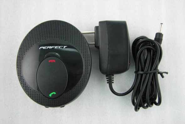
TB6-50X
Jan 14, 2008BT-50X
Equipment Class
DSS - Part 15 Spread Spectrum Transmitter
TB6-803
Mar 04, 2006Bluetooth Headset
Equipment Class
DSS - Part 15 Spread Spectrum Transmitter