TBJTE315MTPMS Exciter
NEXTECH CO., LTD.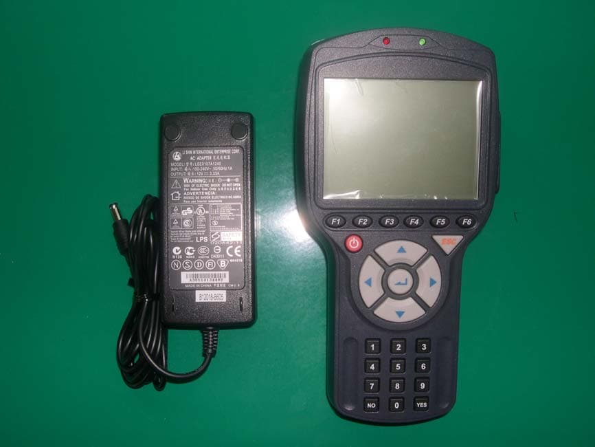
Click to zoom
Application Details
- Equipment Class
- DCD - Part 15 Low Power Transmitter Below 1705 kHz
- Date of Grant
- Jun 09, 2005
- Application Purpose
- Original Equipment
- Date of Application
- Jun 09, 2005
- Equipment Note
- TPMS Exciter
- Frequency Range
- 0.12500000 - 0.12500000
- Company
- NEXTECH CO., LTD.
- Country
- South Korea
Documents & Files
Document Text
Text extracted from the exhibit documents filed with the FCC. Open a document above to read the original.
Users Manual
OPERATION MANUAL PROLOGUE OPERATION GUIDE 2 CAUTION : Any changes or modifications in construction of this device which is not expressly approved by the party Responsible for compliance could void the user’s authority to operate the equipment. NOTE : This equipment has been tested and found to comply with the limits for a Class A digital device, pursuant to part 15 of the FCC Rules. The limits are designed to provide reasonable protection against harmful interference when the equipment is operated in commercial environment. This equipment generates, uses, and can radiate radio frequency energy and, if not installed and used in accordance with the instruction manual, may cause harmful interference to radio area is likely to cause harmful interference in which case the user will be required to correct the interference at his own expense. PROLOGUE OPERATION GUIDE 3 TABLE of CONTENTS SAFETY UNPACKING I. GENERAL INFORMATION 1. GENERAL FEATURES...............................................I-2 2. SPECIFICATIONS....................................................I-3 3. PARTS DESCRIPTION .............................................I-4 II. TPMS DIAGNOSIS 1. CONNECTION METHOD...........................................II-2 2. VEHICLE AND SYSTEM SELECTION.............................II-3 3. DIAGNOSTIC TROUBLE CODES..................................II-5 4. CURRENT DATA.......................................................II-7 5. WARNING STATE.....................................................II-11 6. ACTUATION TEST....................................................II-15 7. ECU INFORMATION..................................................II-18 8. SPECIFIC DATA WRITING..........................................II-20 9. DUAL DISPLAY........................................................II-25 III. TPMS EXCITOR 1. CONNECTION METHOD..........................................III-2 2. VEHICLE AND SYSTEM SELECTION............................III-3 IV. SYSTEM SETUP 1. CONNECTION METHOD..........................................IV-2 2. SYSTEM CONFIGURATION.......................................IV-3 3. DATA SETUP.........................................................IV-5 4. KEY PAD TEST.......................................................IV-7 5. CONTRAST ADJUST SCREEN....................................IV-8 V. SCREEN CAPTURE VIEW 1. OPERATION FLOW...................................................V-2 2. MODE APPLICATION.................................................V-3 3. HOW TO USE THE SCREEN CAPTURE..........................V-5 4. HOW TO USE THE DOWNLOAD FOR PC......................V-6 PROLOGUE OPERATION GUIDE 4 SAFETY Safety Precautions This equipment described in this manual is intended for use only by qualified personnel. Safe and effective use of this equipment is dependent upon the operator following normally accepted safety practices and procedures in conjunction with the special requirements detailed in this manual. Specific warning and cautionary statements will be found, where applicable, throughout this manual. Where necessary, the WARNING statements and ICON will be described in this guide. WARNING identifies conditions or actions which may damage TPMS EXCIER or the vehicle. IMPORTANT WARNING MESSAGES FOR SAFETY ARE AS FOLLOWS: DO NOT DROP TPMS EXCITER MAIN BODY. AND TPMS EXCITER MUST ALWAYS BE COVERED BY THE SHROUD DO NOT PLACE TPMS EXCITER UPON DISTRIBUTOR OF VEHICLE. STRONG ELECTRO-MAGNETIC INTERFERENCE CAN DAMAGE TPMS EXCITER. A STRONG SURGE OR ELECTRONIC SHOCK IN THE POWER SUPPLY LINE CAN DAMAGE TPMS EXCITER POWER SUPPLY. DO NOT USE TPMS EXCITER UNDER THESE HARSH ENVIRONMENT. PROLOGUE OPERATION GUIDE 5 UNPACKING The TPMS EXCITER kit comprises the following standard along with the option kit where ordered. The kit contents should be checked upon receipt and damage or shortages reported to the supplier immediately. [ Figure 0.1 : TPMS EXCITER KIT ] PROLOGUE OPERATION GUIDE 6 1. STANDARD KIT PART NO. PART NAME 1 09900-33000 TPMS EXCITER MAIN BODY 2 09900-33030 DLC CABLE 16 3 09900-33080 CARRYING CASE 4 09900-33040 USB CABLE 5 09900-33060 OPERATION MANUAL 6 09900-33010 RUBBER SHROUD 7 09900-33070 S/W DOWNLOAD CD 8 09900-33050 AD/DC ADAPTOR 9 09900-33020 RECHAGERABLE BATTERY PROLOGUE OPERATION GUIDE 7 ICON OPERATION LEVEL ICON : LEVEL 1 OPERATION(INIT LEVEL) : LEVEL 1 OPERATION(MENU LEVEL) : LEVEL 1 OPERATION(MODE LEVEL) MESSAGE RELATED ICON : PROCESS / RESULT MESSAGE : ERROR MESSAGE : WARNING MESSAGE APPLICATION HELP ICON : SCREEN EXPLANATION : OPERATION GUIDE : HELP / TIPS : NOTE I. GENERAL INFORMATION 1. GENERAL FEATURES.........................................I-2 2. SPECIFICATION................................................1-3 3. PARTS DESCRIPTION........................................I-4 GENERAL INFORMATION OPERATION GUIDE I-2 1. General Features TPMS EXCITER offers the following functionality: On board diagnostic communication Special vehicle test emulation TMPS EXCITER feature include: Diagnostic TPMS communication with HYUNDAI vehicle Diagnostic TPMS communication with KIA vehicles High resolution LCD display Soft touch key Shock protecting rubber shroud PC communication facility PC software download with USB GENERAL INFORMATION OPERATION GUIDE I-3 2. SPECIFICATION CASING Dark gray color High strength ABS material LCD SPEC. 320 by 240 resolution LED Backlight type Standard character output :40 columns 12 Lines KEYPAD Power ON /OFF Key, Soft Function 6 Keys, Arrow 4 Keys, Fixed Functional 4 Keys NUBER 0~9 KEY(10), Enter,ESC,YES/NO Key. Type : Soft Touch Keypad MEMORY CAPACITY Internal Memory : 16 Mbytes Built-in memory OPERATION VOLTAGE 7 – 36 VDC INPUT OPERATING TEMPERATURE 0°C -50°C DLC COMMUNI- CATION LINE TPMS K-Line CAN SAE-J1850 DIMENSION Width : 125mm Length : 223mm Depth : 68/43mm (neck part) BATTERY SMART LI-ION BATTERY, 7 HOUR LIFE FREQUENCY 125KHZ, 315MHZ(AM/FM) POWER CONSUMPTION 3.6 Watts GENERAL INFORMATION OPERATION GUIDE I-4 3. TPMS EXCITER Parts Description (1) TPM…
Text truncated - open the document above for the full version.
Block Diagram
55 44 33 22 11 D D C C B B A A System Structure FPGA 80C196KC ROM SRAM (512KB) FlashMemory(32M) ETC..3.3V FOR FLASH 2678-5V 7V - 10.2V BATT_OUT MAIN CPU DC-12VCar Power 2.5V FOR FPGA MAIN_5VTO CPU BatteryCharger 8V ~ 36V Voltage Down(10.2V) PIC(CAN,J1850,J1587) USB K & L_line Path TPMS MODULE . RS232 PORT LCD CON(320*240) LCD MODULE(320*240) KEY INPUT <Doc> <RevCode> System Structure A2 17 Monday, May 23, 2005 TitleSize Document Number Rev Date: Sheet of CONNECTOR 12V GND TXD R XD LED1 LED2 5V REGULATOR changing Regulator Circuit 125kHz LF Transmitter ANT MAIN CONTROLLER 315㎒ RF Controller 315㎒ Receiver [ TPMS RF Module ] 4MHz 10.178125MHz
Cover Letter(s)
Nextech Co., Ltd. www.nex-tek.com Federal Communications Commission Equipment Authorization Division, Application Processing Branch 7435 Oakland Mills Road Columbia, MD21046 TO WHOM IT MAY CONCERN Pursuant to Paragraphs §0.457 and 0.459 of the Commission's Rules (47 C.F.R) and Section §552(b)(4) of the Freedom of Information Act, Nextech Co., Ltd. requests confidentiality for the following products: FCC ID Number Product Title / Model TBJTE315M TPMS Exciter / TPMS Exciter 315M For the product stated above, we request that the following information be held confidential: 1) Schematic diagrams 2) Bill of materials (Part List) No other items submitted as part of the equipment authorization filing process are deemed confidential. The above exhibits contain Nextech Co., Ltd. trade secrets and proprietary information that could be of benefit to our competitors regarding the design of our products. This material is not customarily available to the general public and we request that it be withheld from public inspection. Sincerely, Young-Hak Kwon / assistant manager email: [email protected] Nextech Co., Ltd. E&C Venture Dream Tower the 3 rd ,13 th Floor, 197-33, Guro-Dong, Guro-Gu, Seoul, Korea Tel: 82-2-3140-1472 Fax: 82-2-3140-1468 http://www.nex-tek.com
External Photos
SK TECH CO., LTD. Page 1 of 2 SKT SKTTRT-050530-009 FCC ID: TBJTE315M External Photographs of EUT Label Location SK TECH CO., LTD. Page 2 of 2 SKT SKTTRT-050530-009 FCC ID: TBJTE315M
ID Label/Location Info
SK TECH CO., LTD. Page 1 of 1 SKT SKTTRT-050530-009 FCC ID: TBJTE315M FCC ID Label Location & Sample Label is permanently attached on the rear of the product 40 mm 25 mm LABEL LOCATION LABEL SAMPLE FCC ID : TBJTE315M Model No.:TPMS Exciter 315M This device complies with part 15 of the FCC Rules. Operation is subject to the following two conditions: (1)This device may not cause harmful interference, and (2) this device must accept any interference received, including interference that may cause undesired operation. NEXTECH CO., LTD.
Internal Photos
SK TECH CO., LTD. Page 1 of 5 SKT SKTTRT-050530-009 FCC ID: TBJTE315M Internal Photographs of EUT <Case Open> SK TECH CO., LTD. Page 2 of 5 SKT SKTTRT-050530-009 FCC ID: TBJTE315M <Main Board_Front> <Main Board_Rear> SK TECH CO., LTD. Page 3 of 5 SKT SKTTRT-050530-009 FCC ID: TBJTE315M <RF Module_Front> <RF Module_Rear> SK TECH CO., LTD. Page 4 of 5 SKT SKTTRT-050530-009 FCC ID: TBJTE315M <LCD_Front> <LCD_Rear> SK TECH CO., LTD. Page 5 of 5 SKT SKTTRT-050530-009 FCC ID: TBJTE315M <Keypad_Front> <Keypad_Rear>
Operational Description
SK TECH CO., LTD. Page 1 of 2 SKT SKTTRT-050530-009 FCC ID: TBJTE315M Operational Description Constitution of the Tire Pressure Monitoring System for vehicle Tire Pressure Monitoring System is the system that receives the information, from transmitters installed at each tire, about the inflation pressure or temperature of tires detected by the sensor, so that the system can detect the abnormality of tires like fallen inflation pressure. This system consists of transmitter, receiving antenna, and receiver. The transmitter sends information of tire, read by the sensor, in the form of radio wave at constant intervals. When the receiver detects the synchronous code and IG is ON, it runs continuously to receive the signals completely. If the received code is normal, the system will not inform the user. As shown below, in the case that the transmitter sends information that the tire is in abnormal condition, and that the receiver system has a trouble, the system will inform the user with lighting up Warning bulb. SK TECH CO., LTD. Page 2 of 2 SKT SKTTRT-050530-009 FCC ID: TBJTE315M ANTENNA Tx : Loop Coil Antenna for 125kHz transmitter. Rx : PCB Pattern Antenna for 315MHz Receiver SPECIFICATION CASING Dark gray color High strength ABS material LCD SPEC. 320 by 240 resolution LED Backlight type Standard character output :40 columns 12 Lines KEYPAD Power ON /OFF Key, Soft Function 6 Keys, Arrow 4 Keys, Fixed Functional 4 Keys NUBER 0~9 KEY(10), Enter,ESC,YES/NO Key. Type : Soft Touch Keypad MEMORY CAPACITY Internal Memory : 16 Mbytes Built-in memory OPERATION VOLTAGE 7 – 36 VDC INPUT OPERATING TEMPERATURE 0°C -50°C DLC COMMUNI- CATION LINE TPMS K-Line CAN SAE-J1850 DIMENSION Width : 125mm Length : 223mm Depth : 68/43mm (neck part) BATTERY SMART LI-ION BATTERY, 7 HOUR LIFE FREQUENCY Tx:125KHz(AM), Rx: 315MHz(AM/FM) POWER CONSUMPTION 3.6 Watts
Test Report
SK TECH CO., LTD. Page 1 of 21 SKT Report No. : SKTTRT-050530-009 FCC ID: TBJTE315M Certificate of Compliance Test Report No.: SKTTRT-050530-009 NVLAP CODE: 200220-0 Applicant: NEXTECH CO., LTD. Applicant Address: E&C Venture Dream Tower the 3 rd ,13 th Floor, 197-33, Guro-Dong, Guro-Gu, Seoul, Korea Device Under Test: TPMS Exciter FCC ID: TBJTE315M Model No.: TPMS Exciter 315M Receipt No.: SKTEU05-0319 Date of receipt: May 20, 2005 Date of Issue: May 30, 2005 Location of Testing: SK TECH CO., LTD. 820-2, Wolmoon-Ri, Wabu-Up, Namyangju-Si, Kyunggi-Do, Korea Test Procedure: ANSI C63.4 / 2003 Test Specification: 47CFR, Part 15 Subpart C Equipment Class: DCD - Part 15 Low Power Transmitter Below 1705kHz CYY - Communications Receiver used with part15 Transmitter Test Result: The above-mentioned device has been tested and passed. Tested & Reported by: Chang-Min, Moon 2005. 05. 30 Approved by: Jae-Kyung, Bae 2005. 05. 30 Signature Date Signature Date Other Aspects: Abbreviations: · OK, Pass = passed · Fail = failed · N/A = not applicable ☞ •This test report is not permitted to copy partly without our permission. •This test result is dependent on only equipment to be used. •This test result is based on a single evaluation of one sample of the above mentioned. •This test report must not be used to claim product endorsement by NVLAP or any agency of the U.S Government. • We certify that this test report has been based on the measurement standards that is traceable to the national or International standards. NVLAP Lab. Code: 200220-0 SK TECH CO., LTD. Page 2 of 21 SKT Report No. : SKTTRT-050530-009 FCC ID: TBJTE315M >> CONTENTS << 1. GENERAL ............................................................................................................. 4 2. TEST SITE ............................................................................................................ 4 2.1 Location ......................................................................................................... 4 2.2 List of Test and Measurement Instruments .................................................... 5 2.3 Test Date ........................................................................................................ 5 2.4 Test Environment ........................................................................................... 5 3. DESCRIPTION OF The EQUIPMENT UNDER TEST .......................................... 6 3.1 Rating and Physical Characteristics .............................................................. 6 3.2 Equipment Modifications ················································································6 3.3 Submitted Documents ····················································································6 4. MEASUREMENT CONDITIONS ........................................................................... 7 4.1 Description of test configuration .................................................................... 7 4.2 List of Peripherals .......................................................................................... 7 4.3 Uncertainty ..................................................................................................... 7 5. TEST AND MEASUREMENTS ............................................................................. 8 5.1 ANTENNA REQUIREMENT .......................................................................... 8 5.1.1 Regulation ............................................................................................... 8 5.1.2 Result ...................................................................................................... 8 5.2 RADIATED EMISSIONS(15.209) .................................................................. 9 5.2.1 Regulation ............................................................................................... 9 5.2.2 Measurement Procedure ......................................................................... 9 5.2.3 Calculation of the filed strength limits...................................................... 10 5.2.4 Test Results ........................................................................................... 10 Table 1: Measured values of the Field strength (below 30MHz) .........................11 Table 2: Measured values of the Field strength (above 30MHz) ......................... 11 5.3 CONDUCTED EMISSIONS(15.207) ···························································12 5.3.1 Regulation ·····························································································12 5.3.2 Test Procedure ······················································································12 5.3.3 Test Results ···························································································13 Table 3: Measured values of the Conducted Emissions··································13 Figure 1: Plot of the Conducted Emissions ..................................................14 5.4 RADIATED EMISSIONS(15.109) ................................................................ 16 5.4.1 Regulation ............................................................................................. 16 5.4.2 Measurement Procedure ....................................................................... 16 5.4.3 Test Results............................................................................................. 17 Table 4: Measured values of the Field strength................................................17 SK TECH CO., LTD. Page 3 of 21 SKT Report No. : SKTTRT-050530-009 FCC ID: TBJTE315M 5.5 CONDUCTED EMISSIONS(15.107) ···························································18 5.3.1 Regulation ·····························································································18 5.3.2 Test Procedure ······················································································18 5.3.3 Test Results ····································································…
Text truncated - open the document above for the full version.
Test Setup Photos
SK TECH CO., LTD. Page 1 of 2 SKT SKTTRT-050530-009 FCC ID: TBJTE315M Test set up photos <Radiated Emissions> SK TECH CO., LTD. Page 2 of 2 SKT SKTTRT-050530-009 FCC ID: TBJTE315M <Conducted Emissions>
Contact Information
Applicant
Young Hak Kwon(Assistant Manager)
Test Firm
SK Tech Co., Ltd.Jae-Yeong Hyun
Technical Specifications
| # | Rule Parts | Frequency Range | Power Output |
|---|---|---|---|
| 1 | 15C | 0.125 MHz - 0.125 MHz | - |
Other Applications from NEXTECH CO., LTD.

TBJNT-TPMS100
Apr 19, 2011TPMS MODULE
Equipment Class
DCD - Part 15 Low Power Transmitter Below 1705 kHz
TBJNT-BT100
Mar 02, 2011USB Bluetooth Adapter
Equipment Class
DSS - Part 15 Spread Spectrum Transmitter