TCQ-BDA-60CELLULAR ZONE ENHANCER
Mars Antennas & RF Systems Ltd.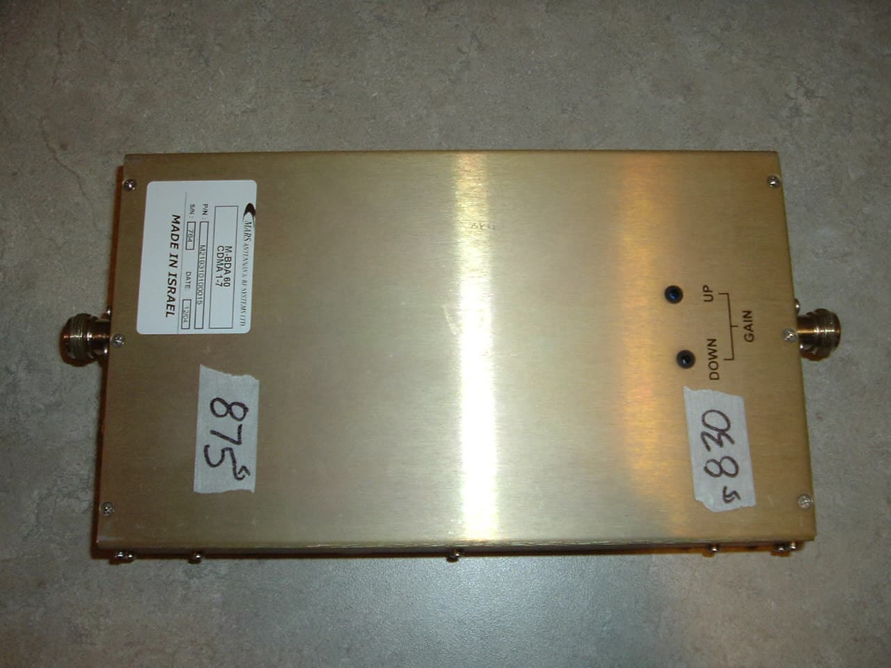
Click to zoom
Application Details
- Equipment Class
- TNB - Licensed Non-Broadcast Station Transmitter
- Date of Grant
- Jun 02, 2005
- Application Purpose
- Original Equipment
- Date of Application
- Jun 02, 2005
- Equipment Note
- CELLULAR ZONE ENHANCER
- Frequency Range
- 869.00000000 - 890.00000000
- Country
- Israel
Documents & Files
Document Text
Text extracted from the exhibit documents filed with the FCC. Open a document above to read the original.
Users Manual
MR-BDA60-X INSTALATION AND OPERATINAL MANUAL 25/03/05 TABLE OF CONTENTS GENERAL INFORMATION GENERAL DESCRIPTION BLOCK DIAGRAM COMPOSITION INSTALLATION ELECTRICAL SPECIFICATION MECHANICAL PERFORMANCE ENVIRONMENTAL Description and Operational Manual of MR-BDA60-X General Information The MR-BDA60-X Bi-Directional Amplifier is designed to enhance radio communication in buildings, basements, parking garage and other RF shielded environments. An MR-BDA60-X system includes all the materials necessary to provide clear, continuous donor site extension coverage within a building or other shadowed location. MR-BDA60-X is suitable for CDMA/TDMA/N-AMPS systems. The small size and flexibility of the MR-BDA60-X system makes it suitable to introduce service to: Shielded buildings (offices, shopping malls, hospitals, airports and underground parking garages or other. General Description MR-BDA60-X Bi-Directional Amplifier is based on a duplexed two path configuration. It features sharp out-of-band attenuation for better selectivity and improved isolation between the receiving and transmitting paths. Passband insertion losses at transmitting path are very low, thus minimizing RF power losses. An MR-BDA60-X system example is show below. Using an external roof or vertical wall-mounted antenna, downlink signals from a donor base station site are received and directed via cable and diplexer to the low noise amplifier (LNA). Low noise amplifier provides gain to set the system noise figure. The next pre-amplifier (Pre-Amp.) provides sufficient signal strength and frequency characteristics to the power amplifier (PA). Power amplifier with highly linear characteristics improves overall system linearity. The signal transmission from the portable back to the donor follows the same principles. Since these amplifiers are Bi-Directional, the uplink signal is amplified in its own amplifier path and routed to the external antenna and back to the donor site. Voltage variable attenuators, couplers in each path and control system provide manual gain control of each channel. The DC system current consumption and abnormal operation in each path are monitored by means of LED indicators. The MR-BDA60-X Bi-Directional Amplifier is a low-power, high-gain device. A compact, lightweight, weatherproof box will mounting, assures easy and reliable installation. MR-BDA60-X BLOCK DIAGRAM U7 PA In Out DONOR ANTENNA "GAIN UP" U5 Dip lexer Ant TX RX J1 Con_RF "MOBILE" Band Pass Filter U2 BPF_0 ATT_1 VR2 "SITE (DC IN)" SERVICE AREA Band Pass Filter U8 BPF_0 "12V" U9 LNA In Out Uplink 824-834 MHz U6 Power Supply In Out L1 INDUCTOR Downlink 869-879 MHz U1 LNA In Out U4 Diplexer Ant TX RX ATT_1 VR1 +VCC U3 PA In Out J2 Con_RF "GAIN DOWN" Composition On the front panel of MR-BDA60-X are placed RF connector “MOBILE” for connection with Up Link part of antenna and 3 LEDs. Green LED “ON” is light when DC power from external power supply +12V or from RF connector “MOBILE” is on. Two red LEDs “OVERLOAD” are indicators of abnormal operation in each channel. LED “DOWN” is on when input signal of channel “MOBILE” (Up Link) is big and the channel in position 1 dB compression. LED “UP” is on when input signal of channel “SITE” (Down Link) is big and the channel in position 1 dB compression. On the rear panel are placed RF connector “SITE (DC IN)” for connection with Down Link part of antenna and DC connector “12V” for connection with external power supply +12VDC. On the higher side of MR-BDA60-X are placed two holes for manual control of gain in each channel. Gain manual controls are provided with potentiometers in each channel of MR-BDA60-X. Potentiometer “DOWN” provides manual gain control in Up Link. Potentiometer “UP” provides gain control in Down Link. Installation 1. Install MR-BDA60-B1 on the place and support the casing with four screws through four mounting holes. 2. Check the isolation between the donor antenna and mobile antenna. 3. Connect RF cable with RF connector “MOBILE” of MR-BDA60-B1 and Mobile part of antenna. 4. Connect RF cable with connector “SITE (DC IN)” of MR-BDA60-B1 and Base part of antenna. 5. Connect DC connector “12V” with +12VDC power supply and connect the AC adaptor 220 to 220VAC check that the green led is turned “ON”. 6. Adjust the potentiometer Gain Down on the top cover until you receive sufficient signal on your portable test equipment. Pay attention that while adjusting the Gain Down the Overload Down red led in front panel will not turn “ON”. 7. Repeat the same procedure (paragraph 6) for the Gain UP adjustment. Bi-Directional Amplifier MR-BDA60-X Mars BDA series of products provides a cost effective answer for enhancing radio communication in buildings, basements, parking garages and other RF shielded environments. The BDA products work by receiving and amplifying RF signals strength in both the "Down Link" and the "Up Link" communication paths. Specifications: Electrical Down Link (Base to Mobile) Up Link (Mobile to Base) Frequency Range, MHz 869 - 894 824 - 849 Operational Frequency Band, MHz (other available on request) 869 - 879 824 - 834 Gain at min. Attenuation 55 dB 60 dB Pass Band Ripple ± 1.5 dB ± 1.5 dB Output Power @ 1 dB Compression 26 dBm 19 dBm Noise Figure, max. 6.5 dB 6.5 dB Gain Control, manual 20 dB 20 dB Impedance 50 Ohm 50 Ohm VSWR, max. 2:1 2:1 Output IP3, min. 40 dBm 31 dBm Input Power, max. -15 dBm -15 dBm Biasing (via RF cable and through separate DC Connector) 12V/1000 mA; Adaptor MR-PS26 should be separately ordered. Mechanical and Environmental Dimensions 253x125x43 mm Weight 850 g RF Connector N-Type Female Operating Temperature -10°C to +50°C Relative Humidity 95% Splash, Dust Protected Specifications subject to change without notice
Block Diagram
MR-BDA60-X BLOCK DIAGRAM U7 PA In Out DONOR ANTENNA "GAIN UP" U5 Dip lexer Ant TX RX J1 Con_RF "MOBILE" Band Pass Filter U2 BPF_0 ATT_1 VR2 "SITE (DC IN)" SERVICE AREA Band Pass Filter U8 BPF_0 "12V" U9 LNA In Out Uplink 824-834 MHz U6 Power Supply In Out L1 INDUCTOR Downlink 869-879 MHz U1 LNA In Out U4 Diplexer Ant TX RX ATT_1 VR1 +VCC U3 PA In Out J2 Con_RF "GAIN DOWN"
Cover Letter(s)
May 13, 2005 Federal Communications Commission 445 12th Street SW Washington, DC 20554 Re: Request for Confidentiality FCC ID: PENDING In accordance with FCC Rules part 0.459, we hereby request confidential treatment for the above referenced Certification application. The items to be held in confidence are: Confidential - 2193(bda 60db)_AssyA.pdf.pdf 2193_2 BDA60-B1)_AssyA.pdf 2193_1 (BDA60-X)_PCB Schematics for the MR-BDA-60 Confidential – MR-BDA60 FCC Appendix A int photos (Confidential).PDF Interior photos of the unit. The application contains technical information that which Mars Antenna and RF Systems Ltd. deem to be trade secrets and proprietary. If made public, the information might be used to the disadvantage of the applicant in the market place. Since the product is sealed using a one time sealant and contains no user serviceable parts, the Interior Photos are only of use to the applicant’s competitors. Thank you for your attention in this matter Solo Alterescu Engineering Director MARS Antennas & RF-Systems
External Photos
EMC LABS INC Tranzeo EMC Labs Inc. #2 - 11720 Stewart Crescent Maple Ridge, BC Canada V2X 9E7 MR-BDA-60 Test Report Appendix B – External Photos 13 May 2005 Report Number: TRL130505.1 Bruce Balston, EMC Lab Manager Andrew Marles, Technical Writer Report Number: TRL130505.1 Emissions Compliance Test Tranzeo EMC Labs Inc. Page 2 of 2 Appendix B B.1 External Photos Figure 1 – External, sealed front cover of unit
ID Label/Location Info
Mars Antennas & RF Systems This device complies with Part 15 of the FCC Rules. Operation is subject to the following two conditions: (1) this device may not cause harmful interference, and (2) this device must accept any interference received, including interference that may cause undesired operation. MR-BDA-60-X FCC ID: TCQ-BDA60 IC: 1234-BDA60 Serial #:764
ID Label/Location Info
EMC LABS INC Tranzeo EMC Labs Inc. #2 - 11720 Stewart Crescent Maple Ridge, BC Canada V2X 9E7 MR-BDA-60 Test Report Appendix C – Label Location 13 May 2005 Report Number: TRL130505.1 Bruce Balston, EMC Lab Manager Andrew Marles, Technical Writer Report Number: TRL130505.1 Emissions Compliance Test Tranzeo EMC Labs Inc. Page 2 of 2 Appendix C C.1 FCC Label location Figure 1 – External back panel, FCC Label location..
Operational Description
EMC LABS INC Tranzeo EMC Labs Inc. #2 - 11720 Stewart Crescent Maple Ridge, BC Canada V2X 9E7 MR-BDA-60 Test Report Appendix E – Operational Description 13 May 2005 Report Number: TRL130505.1 Bruce Balston, EMC Lab Manager Andrew Marles, Technical Writer Report Number: TRL130505.1 Emissions Compliance Test Tranzeo EMC Labs Inc. Page 2 of 2 Appendix E E.1 Operational Description The Mars BDA series of products provides a cost effective answer for enhancing radio communication in buildings, basements, parking garages and other RF shielded environments. The BDA products work by receiving and amplifying RF signals strength in both the "Down Link" and the "Up Link" communication paths.
Parts List/Tune Up Info
Create PDF with GO2PDF for free, if you wish to remove this line, click here to buy Virtual PDF Printer
Parts List/Tune Up Info
MR-BDA60-X INSTALATION AND OPERATINAL MANUAL 25/03/05 TABLE OF CONTENTS GENERAL INFORMATION GENERAL DESCRIPTION BLOCK DIAGRAM COMPOSITION INSTALLATION ELECTRICAL SPECIFICATION MECHANICAL PERFORMANCE ENVIRONMENTAL Description and Operational Manual of MR-BDA60-X General Information The MR-BDA60-X Bi-Directional Amplifier is designed to enhance radio communication in buildings, basements, parking garage and other RF shielded environments. An MR-BDA60-X system includes all the materials necessary to provide clear, continuous donor site extension coverage within a building or other shadowed location. MR-BDA60-X is suitable for CDMA/TDMA/N-AMPS systems. The small size and flexibility of the MR-BDA60-X system makes it suitable to introduce service to: Shielded buildings (offices, shopping malls, hospitals, airports and underground parking garages or other. General Description MR-BDA60-X Bi-Directional Amplifier is based on a duplexed two path configuration. It features sharp out-of-band attenuation for better selectivity and improved isolation between the receiving and transmitting paths. Passband insertion losses at transmitting path are very low, thus minimizing RF power losses. An MR-BDA60-X system example is show below. Using an external roof or vertical wall-mounted antenna, downlink signals from a donor base station site are received and directed via cable and diplexer to the low noise amplifier (LNA). Low noise amplifier provides gain to set the system noise figure. The next pre-amplifier (Pre-Amp.) provides sufficient signal strength and frequency characteristics to the power amplifier (PA). Power amplifier with highly linear characteristics improves overall system linearity. The signal transmission from the portable back to the donor follows the same principles. Since these amplifiers are Bi-Directional, the uplink signal is amplified in its own amplifier path and routed to the external antenna and back to the donor site. Voltage variable attenuators, couplers in each path and control system provide manual gain control of each channel. The DC system current consumption and abnormal operation in each path are monitored by means of LED indicators. The MR-BDA60-X Bi-Directional Amplifier is a low-power, high-gain device. A compact, lightweight, weatherproof box will mounting, assures easy and reliable installation. MR-BDA60-X BLOCK DIAGRAM U7 PA In Out DONOR ANTENNA "GAIN UP" U5 Dip lexer Ant TX RX J1 Con_RF "MOBILE" Band Pass Filter U2 BPF_0 ATT_1 VR2 "SITE (DC IN)" SERVICE AREA Band Pass Filter U8 BPF_0 "12V" U9 LNA In Out Uplink 824-834 MHz U6 Power Supply In Out L1 INDUCTOR Downlink 869-879 MHz U1 LNA In Out U4 Diplexer Ant TX RX ATT_1 VR1 +VCC U3 PA In Out J2 Con_RF "GAIN DOWN" Composition On the front panel of MR-BDA60-X are placed RF connector “MOBILE” for connection with Up Link part of antenna and 3 LEDs. Green LED “ON” is light when DC power from external power supply +12V or from RF connector “MOBILE” is on. Two red LEDs “OVERLOAD” are indicators of abnormal operation in each channel. LED “DOWN” is on when input signal of channel “MOBILE” (Up Link) is big and the channel in position 1 dB compression. LED “UP” is on when input signal of channel “SITE” (Down Link) is big and the channel in position 1 dB compression. On the rear panel are placed RF connector “SITE (DC IN)” for connection with Down Link part of antenna and DC connector “12V” for connection with external power supply +12VDC. On the higher side of MR-BDA60-X are placed two holes for manual control of gain in each channel. Gain manual controls are provided with potentiometers in each channel of MR-BDA60-X. Potentiometer “DOWN” provides manual gain control in Up Link. Potentiometer “UP” provides gain control in Down Link. Installation 1. Install MR-BDA60-B1 on the place and support the casing with four screws through four mounting holes. 2. Check the isolation between the donor antenna and mobile antenna. 3. Connect RF cable with RF connector “MOBILE” of MR-BDA60-B1 and Mobile part of antenna. 4. Connect RF cable with connector “SITE (DC IN)” of MR-BDA60-B1 and Base part of antenna. 5. Connect DC connector “12V” with +12VDC power supply and connect the AC adaptor 220 to 220VAC check that the green led is turned “ON”. 6. Adjust the potentiometer Gain Down on the top cover until you receive sufficient signal on your portable test equipment. Pay attention that while adjusting the Gain Down the Overload Down red led in front panel will not turn “ON”. 7. Repeat the same procedure (paragraph 6) for the Gain UP adjustment. Bi-Directional Amplifier MR-BDA60-X Mars BDA series of products provides a cost effective answer for enhancing radio communication in buildings, basements, parking garages and other RF shielded environments. The BDA products work by receiving and amplifying RF signals strength in both the "Down Link" and the "Up Link" communication paths. Specifications: Electrical Down Link (Base to Mobile) Up Link (Mobile to Base) Frequency Range, MHz 869 - 894 824 - 849 Operational Frequency Band, MHz (other available on request) 869 - 879 824 - 834 Gain at min. Attenuation 55 dB 60 dB Pass Band Ripple ± 1.5 dB ± 1.5 dB Output Power @ 1 dB Compression 26 dBm 19 dBm Noise Figure, max. 6.5 dB 6.5 dB Gain Control, manual 20 dB 20 dB Impedance 50 Ohm 50 Ohm VSWR, max. 2:1 2:1 Output IP3, min. 40 dBm 31 dBm Input Power, max. -15 dBm -15 dBm Biasing (via RF cable and through separate DC Connector) 12V/1000 mA; Adaptor MR-PS26 should be separately ordered. Mechanical and Environmental Dimensions 253x125x43 mm Weight 850 g RF Connector N-Type Female Operating Temperature -10°C to +50°C Relative Humidity 95% Splash, Dust Protected Specifications subject to change without notice
Test Report
EMC LABS INC Tranzeo EMC Labs Inc. #2 - 11720 Stewart Crescent Maple Ridge, BC Canada V2X 9E7 Mars Antenna & RF Systems MR-BDA-60 Amplifier EMC Test Report 13 May 2005 Report Number: TRL130505.1 Bruce Balston, EMC Lab Manager Andrew Marles, Technical Writer Report Number: TRL130505.1 Emissions Compliance Test Tranzeo EMC Labs Inc. Page 2 of 28 Revision History Report Number: TRL130505.1 Emissions Compliance Test Tranzeo EMC Labs Inc. Page 3 of 28 Table of Contents 1.0 General Information ...................................................................................................................................................4 1.1 EUT Description ..................................................................................................................................................4 1.2 Operational Description .......................................................................................................................................4 1.3 EUT Testing Configuration .................................................................................................................................4 1.4 EUT Modifications ..............................................................................................................................................5 1.5 Overview of Test Results .....................................................................................................................................5 1.6 Test Facilities .......................................................................................................................................................6 1.7 Test Equipment ....................................................................................................................................................6 1.8 Test System Details..............................................................................................................................................6 1.9 Test Results..........................................................................................................................................................6 2.0 Conducted Emissions ..................................................................................................................................................7 2.1 Test Standard .......................................................................................................................................................7 2.2 Test Limits ...........................................................................................................................................................7 2.3 Test Setup ............................................................................................................................................................7 2.4 Test Results..........................................................................................................................................................8 3.0 RF Output Power ........................................................................................................................................................9 3.1 Test Standard .......................................................................................................................................................9 3.2 Test Limits ...........................................................................................................................................................9 3.3 Test Setup ............................................................................................................................................................9 3.4 Test Results..........................................................................................................................................................9 4.0 Transmitter Radiated Spurious Emissions .............................................................................................................10 4.1 Test Standard .....................................................................................................................................................10 4.2 Test Limits .........................................................................................................................................................10 4.3 Test Setup ..........................................................................................................................................................11 4.4 Test Results........................................................................................................................................................12 5.0 Transmitter Conducted Harmonic and Spurious Emissions .................................................................................13 5.1 Test Standard .....................................................................................................................................................13 5.2 Test Limits .........................................................................................................................................................13 5.3 Test Setup ..........................................................................................................................................................13 5.4 Test Results........................................................................................................................................................14 6.0 Band Edge ..................................................................................................................................................................15 6.1 Test Standard .....................................................................................................................................................15 6.2 Test Limits ................................................................................................…
Text truncated - open the document above for the full version.
Test Report
EMC LABS INC Tranzeo EMC Labs Inc. #2 - 11720 Stewart Crescent Maple Ridge, BC Canada V2X 9E7 MR-BDA-60 Test Report Appendix F – MFE Evaluation 13 May 2005 Report Number: TRL130505.1 Bruce Balston, EMC Lab Manager Andrew Marles, Technical Writer Report Number: TRL130505.1 Emissions Compliance Test Tranzeo EMC Labs Inc. Page 2 of 2 Appendix E MFE Evaluation FCC 1.1310 states the criteria listed in the table below shall be used to evaluate the environmental impact of human exposure to radiofrequency (RF) radiation as specified in Sec. 1.1307(b), except in the case of portable devices which shall be evaluated according to the provisions of Sec. 2.1093 of this chapter. Further information on evaluating compliance with these limits can be found in the FCC's OST/OET Bulletin Number 65, ``Evaluating Compliance with FCC-Specified Guidelines for Human Exposure to Radiofrequency Radiation.'' Frequency Range (MHZ) Electric Field Strength (V/m) Magnetic Field Strength (A/M) Power Density (mW/cm 2 ) Average Time (A) Limits for Occupational/Control Exposures 300-1500 -- -- F/300 6 1500-100,000 -- -- 5 6 (B) Limits for General Population/Uncontrolled Exposures 300-1500 -- -- F/1500 6 1500-100,000 -- -- 1 30 9.1 Fries Formula Fries transmission formula: Pd = (P out *G)/(4* p*r 2 ) Where Pd = power density in mW/cm 2 P out = output power to antenna in mW. G = gain of antenna in the direction of interest relative to an isotropic radiator. R = the distance between the observation point and the center of the radiator in cm. Pd is the limit of MPE, 1mW/cm 2 . If we know the maximum gain of the antenna and the total power input to the antenna we can calculate the distance r where the MPE limit is reached. 9.2 EUT Operating Condition The maximum output power of the EUT is 26 dBm as tested and specified by the manufacturer. An antenna gain of 6 dBi is assumed. 9.3 RF exposure evaluation distance calculation Freq (MHz) Output Power to Antenna (dBm) Output Power to Antenna (mW) Antenna Gain (dBi) r (cm) 824 23 200 6 5 894 26 400 6 7 As shown above, the minimum distance where the MPE limit is reached is 7 cm for this EUT
Contact Information
Applicant
Solo Alterescu(Engineering Director)
Test Firm
Tranzeo EMC Labs Inc.Andrei Moldavanov
Technical Specifications
| # | Rule Parts | Frequency Range | Power Output | Emission | Tolerance |
|---|---|---|---|---|---|
| 6 | 22H | 869 MHz - 890 MHz | 400.00 mW | FID | Amp |