Text extracted from the exhibit documents filed with the FCC. Open a document above to read the original.
Bountiful WiFi Quick Start Guide BWR54G1 Materials Checklist Check to make sure you have all of the materials provided for setting up the BWR54G1 Access Point / Router: 1. Quick Start Guide 2. Bountiful WiFi Access Point / Router 3. AC/DC power supply 4. CAT-5 Ethernet networking cable Overview With your new router you will be able to share your Internet connection and network your computers. Web-based Setup The router is easily configured, including advanced functionality, with your web browser without installing extra software or programs. You can thereby manage the router and update settings from any computer on the network. LED Status Indicators On the front of the router are LEDs to indicate the status of your WLAN, WAN and LAN connections. Function LED Display On Blinking Off Power Green System On NA System Off Router status Green Active NA Inactive WLAN Green WLAN connected WLAN data transmit / receive Inactive WLAN WAN Green WAN connected WAN activity Inactive WAN LAN 1 Green Ethernet Link Transmitting / receiving data Disconnected LAN 2 Green Ethernet Link Transmitting / receiving data Disconnected LAN 3 Green Ethernet Link Transmitting / receiving data Disconnected LAN 4 Green Ethernet Link Transmitting / receiving data Disconnected IP Address Sharing The router uses Network Address Translation (NAT) to share the single IP address assigned to you by your ISP, saving the cost of adding additional IP addresses to your Internet service. Firewall The router is equipped with a firewall to protect you from a wide array of hacker attacks. Integrated 10/100 Fast Ethernet 4-Port Switch This router has a four-port network switch allowing you to connect your wired LAN computers into the network, thereby sharing printers, data files, etc. The switch features automatic speed detection to adjust to the speed of the connected devices. VPN Pass-through Your router will allow your VPN-equipped computer to pass through the Router to your office network if you connect to your office network through your home using a VPN connection. DHCP (Dynamic Host Configuration Protocol) DHCP, supported on this router, allows the easiest connections to a network. The DHCP server assigns an IP address to each computer or device automatically. Controlling Access through MAC Address Filtering For added security, you can set up a list of MAC addresses (unique client identifiers in each networking device)) that are allowed to access your network. Every computer has its own MAC address. Simply enter these into a list using the web-based user interface. Installation and Configuration Step 1: Install Wireless Access Point / Router Note: Your router should be placed in a location that is central to where your computers will be used. A. Power your computer and DSL/cable modem down. β’ Using the network cable that came with the modem, connect the modem to the WAN port on the back of the Wireless Access Point / Router. β’ If your DSL or cable modem is currently connected to your computer, disconnect it from your computer. If you wish to configure the Wireless Access Point / Router via a wired connection, connect the computer with the network cable provided to one of the LAN ports at the back of the Wireless Access Point / Router. B. If all computers in your network will be wireless, then no other connections need to be made to the Wireless Access Point / Router. C. Power up your broadband modem and wait for the lights to stop flashing. D. Attach the two antennas included and power up your Wireless Access Point / Router by connecting the power supply to the Power port on the back and then connecting to a power outlet. The Power LED on the front of the Wireless Access Point / Router should illuminate green. E. Turn the computer back on. Step 2: Setting up your PC Follow the steps below for the operating system of the computer that was originally connected to the DSL or cable modem or the computer that is the closest to the modem. A. If you have Windows 98 or Me: 1. Click the Start button, select Settings and then Control Panel. 2. Double click on the Network icon. 3. In the Configuration window scroll down to the bottom. Highlight the TCP/IP that has been associated with your network adapter or adapter (example: TCP/IP- > Instant Wireless Network PC Adapter). Do not highlight any TCP/IP that says Dial-Up Adapter. 4. Once you have highlighted the appropriate network adapter, double click and select the IP Address tab. 5. If Obtain an IP address automatically is selected and you have a dynamic IP address click OK and go to Step C. 6. If Obtain an IP address automatically is selected and you have a static IP address click OK and go to Step D (your computer may require a restart). 7. If Specify an IP address is selected, write down the IP Address ____________________ and Subnet Mask____________________. Then change to Obtain an IP address automatically by clicking the radio button. Click on the Gateway tab, write down the Installed Gateway ____________________ and then highlight and click remove. Click on the DNS Configuration tab and write down the DNS Server Search Order ____________________ numbers in the middle window, then click the Disable DNS radio button at the top. Click OK to close each window and restart your computer. Then go to Step D and use the information you just wrote down. B. If you have Windows 2000 or XP: 1. Click the Start button, select Settings (skip Settings for XP) and then Control Panel. 2. Double click on the Network and Dial-up Connections icon. 3. Double click on the Local Area Connection icon. 4. Click on the Properties button and double click on the Internet Protocol (TCP/IP). 5. If Obtain an IP address automatically is selected and you have a dynamic IP address, go to Step C. 6. If Obtain an IP address automatically is selected and you have a static IP address, go to Step D. 7. If Use the following IP address is selected, write down the IP Address ____________________, Subnet Mask_________________β¦
Text truncated - open the document above for the full version.
1 Helen Zhao From:Danielle Zhan Sent:Tuesday, July 05, 2005 3:45 PM To:Helen Zhao Subject:RE: Bountiful WiFi LLC, FCC ID: TDK-BWR54G1, Assessment NO.: AN05T4894, Notice#2 Dear Helen, Please find responses below which address your questions. Thank you for your further review. Danielle -----Original Message----- From: Compliance Certification Services [mailto:[email protected]] Sent: Thursday, June 30, 2005 4:48 PM To: Helen Zhao Subject: Bountiful WiFi LLC, FCC ID: TDK-BWR54G1, Assessment NO.: AN05T4894, Notice#2 Question #3: Test Report page 60 & 61: The plots are not Low channel mode b as the title suggested. Please revise the test report. [Danielle] Please see revised report as attached. 05U3488-1B FCC DTS Report.pdf... Question #4: Please confirm the antenna port channel test was done at the end of amplifier + LPF, not the RF radio end, i.e. 0.5W amplifier ouput is already taken into consideration. [Danielle] Yes confirmed that measurements were made at the output of the amp and LPF. -----Original Message----- From: Compliance Certification Services [mailto:[email protected]] Sent: Sunday, June 26, 2005 12:43 PM To: Helen Zhao Subject: Bountiful WiFi LLC, FCC ID: TDK-BWR54G1, Assessment NO.: AN05T4894, Notice#1 Question #1: Please submit Test Report. [Danielle] See attached. << File: 05U3488 FCC DTS Report.pdf >> Question #2: Please revise the user manual to add non-colocation restriction statement. [Danielle] Revised as attached. << File: TDK-BWR54G1 Quickstart users' guide.revised.pdf >> 2 Best Regards, Helen Zhao The items indicated above must be submitted before processing can continue on the above referenced application. Failure to provide the requested information within 30 days of the original e-mail date may result in application dismissal and forfeiture of the filing fee. Also, please note that partial responses increase processing time and should not be submitted. Any questions about the content of this correspondence should be directed to the e-mail address listed below the name of the sender.
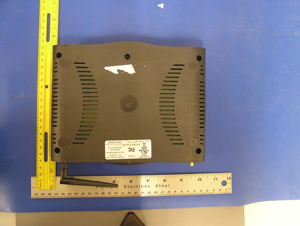
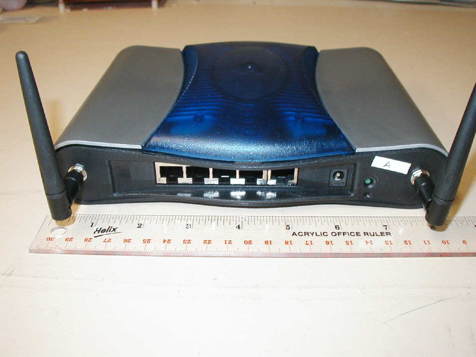
TDK-BWR54G1 external photos, June 16, 2005
TDK-BWR54G1 Proposed FCC ID label and location β June 16, 2005
TDK-BWR54G1 internal photos, June 16, 2005
Specifications Electrical Specifications Frequency 2400-2500 MHz Gain 2.2 dBi Impedance 50 Ohm VSWR < 2.0 Mechanical Specifications Weight 0.52 oz. (15 g) Length 4.7" (105 mm) Diameter 0.4" (10 mm) Finish Matte Black Connector Reverse Polarity SMA Plug Operating Temperature -40Β° C to to 85Β° C (-40Β° F to 185Β° F) Polarization Vertical Antenna Gain Pattern
FCC CFR47 PART 15 SUBPART C CERTIFICATION TEST REPORT FOR 802.11 B/G ACCESS POINT MODEL NUMBER: BWR54G1 FCC ID: TDK-BWR54G1 REPORT NUMBER: 05U3488-1B ISSUE DATE: JULY 5, 2005 Prepared for BOUNTIFUL WIFI LLC 707 WEST 700 SOUTH, SUITE 202A WOODS CROSS, UT 84087 U.S.A Prepared by COMPLIANCE ENGINEERING SERVICES, INC. d.b.a. COMPLIANCE CERTIFICATION SERVICES 561F MONTEREY ROAD, MORGAN HILL, CA 95037, USA TEL: (408) 463-0885 FAX: (408) 463-0888 REPORT NO: 05U3488-1B DATE: JULY 5, 2005 EUT: 802.11 b/g Access Point FCC ID: TDK-BWR54G1 Page 2 of 90 COMPLIANCE CERTIFICATION SERVICES DOCUMENT NO: CCSUP4031A 561F MONTEREY ROAD, MORGAN HILL, CA 95037 USA TEL: (408) 463-0885 FAX: (408) 463-0888 This report shall not be reproduced except in full, without the written approval of CCS. Revision History Rev. Issue Date Revisions Revised By A 6/15/05 Initial Issue MH B 7/5/05 Corrected Plots on Page 60-61 MH REPORT NO: 05U3488-1B DATE: JULY 5, 2005 EUT: 802.11 b/g Access Point FCC ID: TDK-BWR54G1 Page 3 of 90 COMPLIANCE CERTIFICATION SERVICES DOCUMENT NO: CCSUP4031A 561F MONTEREY ROAD, MORGAN HILL, CA 95037 USA TEL: (408) 463-0885 FAX: (408) 463-0888 This report shall not be reproduced except in full, without the written approval of CCS. TABLE OF CONTENTS 1. ATTESTATION OF TEST RESULTS............................................................................................. 4 2. TEST METHODOLOGY .................................................................................................................. 5 3. FACILITIES AND ACCREDITATION .......................................................................................... 5 4. CALIBRATION AND UNCERTAINTY.......................................................................................... 5 4.1. MEASURING INSTRUMENT CALIBRATION ............................................................................. 5 4.2. MEASUREMENT UNCERTAINTY ............................................................................................... 5 5. EQUIPMENT UNDER TEST............................................................................................................6 5.1. DESCRIPTION OF EUT ..............................................................................................................6 5.2. MAXIMUM OUTPUT POWER .................................................................................................... 6 5.3. DESCRIPTION OF AVAILABLE ANTENNAS ............................................................................. 6 5.4. SOFTWARE AND FIRMWARE .................................................................................................... 6 5.5. WORST-CASE CONFIGURATION AND MODE......................................................................... 6 5.6. MODIFICATION INFORMATION............................................................................................... 7 5.7. DESCRIPTION OF TEST SETUP ................................................................................................ 8 6. TEST AND MEASUREMENT EQUIPMENT .............................................................................. 10 7. LIMITS AND RESULTS ................................................................................................................. 11 7.1. CHANNEL TESTS FOR THE 2400 TO 2483.5 MHz BAND ...................................................... 11 7.1.1. 6 dB BANDWIDTH ........................................................................................................... 11 7.1.2. 99% BANDWIDTH............................................................................................................ 18 7.1.3. PEAK OUTPUT POWER .................................................................................................. 25 7.1.4. MAXIMUM PERMISSIBLE EXPOSURE ........................................................................ 33 7.1.5. AVERAGE POWER........................................................................................................... 36 7.1.6. PEAK POWER SPECTRAL DENSITY ............................................................................ 37 7.1.7. CONDUCTED SPURIOUS EMISSIONS.......................................................................... 44 7.2. RADIATED EMISSIONS.............................................................................................................57 7.2.1. TRANSMITTER RADIATED SPURIOUS EMISSIONS ................................................. 57 7.2.2. TRANSMITTER ABOVE 1 GHz FOR 2400 TO 2483.5 MHz BAND ............................. 60 7.2.3. WORST-CASE RADIATED EMISSIONS BELOW 1 GHz ............................................. 78 7.3. POWERLINE CONDUCTED EMISSIONS ................................................................................ 82 8. SETUP PHOTOS .............................................................................................................................. 86 REPORT NO: 05U3488-1B DATE: JULY 5, 2005 EUT: 802.11 b/g Access Point FCC ID: TDK-BWR54G1 Page 4 of 90 COMPLIANCE CERTIFICATION SERVICES DOCUMENT NO: CCSUP4031A 561F MONTEREY ROAD, MORGAN HILL, CA 95037 USA TEL: (408) 463-0885 FAX: (408) 463-0888 This report shall not be reproduced except in full, without the written approval of CCS. 1 ATTESTATION OF TEST RESULTS COMPANY NAME: BOUNTIFUL WIFI LLC 707 WEST 700 SOUTH, SUITE 202A WOODS CROSS, UT 84087, U.S.A EUT DESCRIPTION: 802.11b/g ACCESS POINT MODEL: BWR54G1 SERIAL NUMBER: 01550 DATE TESTED: JUNE 10-14, 2005 APPLICABLE STANDARDS STANDARD TEST RESULTS FCC PART 15 SUBPART C NO NON-COMPLIANCE NOTED Compliance Certification Services, Inc. tested the above equipment in accordance with the requirements set forth in the above standards. The test results show that the equipment tested is capable of demonstrating compliance with the requirements as documented in this report. Note: The results documented in this report apply only to the tested sample, under the conditions and modes of operation aβ¦
Text truncated - open the document above for the full version.
REPORT NO: 05U3488 DATE: JUNE 20, 2005 EUT: 802.11 b/g Access Point FCC ID: TDK-BWR54G1 Page 86 of 90 COMPLIANCE CERTIFICATION SERVICES DOCUMENT NO: CCSUP4031A 561F MONTEREY ROAD, MORGAN HILL, CA 95037 USA TEL: (408) 463-0885 FAX: (408) 463-0888 This report shall not be reproduced except in full, without the written approval of CCS. 8. SETUP PHOTOS ANTENNA PORT CONDUCTED RF MEASUREMENT SETUP ANTENNA PORT CONDUCTED PHOTO REPORT NO: 05U3488 DATE: JUNE 20, 2005 EUT: 802.11 b/g Access Point FCC ID: TDK-BWR54G1 Page 87 of 90 COMPLIANCE CERTIFICATION SERVICES DOCUMENT NO: CCSUP4031A 561F MONTEREY ROAD, MORGAN HILL, CA 95037 USA TEL: (408) 463-0885 FAX: (408) 463-0888 This report shall not be reproduced except in full, without the written approval of CCS. RADIATED RF MEASUREMENT SETUP RADIATED FRONT PHOTO REPORT NO: 05U3488 DATE: JUNE 20, 2005 EUT: 802.11 b/g Access Point FCC ID: TDK-BWR54G1 Page 88 of 90 COMPLIANCE CERTIFICATION SERVICES DOCUMENT NO: CCSUP4031A 561F MONTEREY ROAD, MORGAN HILL, CA 95037 USA TEL: (408) 463-0885 FAX: (408) 463-0888 This report shall not be reproduced except in full, without the written approval of CCS. RADIATED BACK PHOTO REPORT NO: 05U3488 DATE: JUNE 20, 2005 EUT: 802.11 b/g Access Point FCC ID: TDK-BWR54G1 Page 89 of 90 COMPLIANCE CERTIFICATION SERVICES DOCUMENT NO: CCSUP4031A 561F MONTEREY ROAD, MORGAN HILL, CA 95037 USA TEL: (408) 463-0885 FAX: (408) 463-0888 This report shall not be reproduced except in full, without the written approval of CCS. POWERLINE CONDUCTED EMISSIONS MEASUREMENT SETUP LINE CONDUCTED FRONT PHOTO REPORT NO: 05U3488 DATE: JUNE 20, 2005 EUT: 802.11 b/g Access Point FCC ID: TDK-BWR54G1 Page 90 of 90 COMPLIANCE CERTIFICATION SERVICES DOCUMENT NO: CCSUP4031A 561F MONTEREY ROAD, MORGAN HILL, CA 95037 USA TEL: (408) 463-0885 FAX: (408) 463-0888 This report shall not be reproduced except in full, without the written approval of CCS. END OF REPORT LINE CONDUCTED BACK PHOTO
| # | Rule Parts | Frequency Range | Power Output |
|---|---|---|---|
| 1 | 15C | 2.41 GHz - 2.46 GHz | 820.40 mW |

802.11 b/g Access Point
Equipment Class
DTS - Digital Transmission System