TDOAVIACOM1VHF aviation transceiver
MB Martin & Company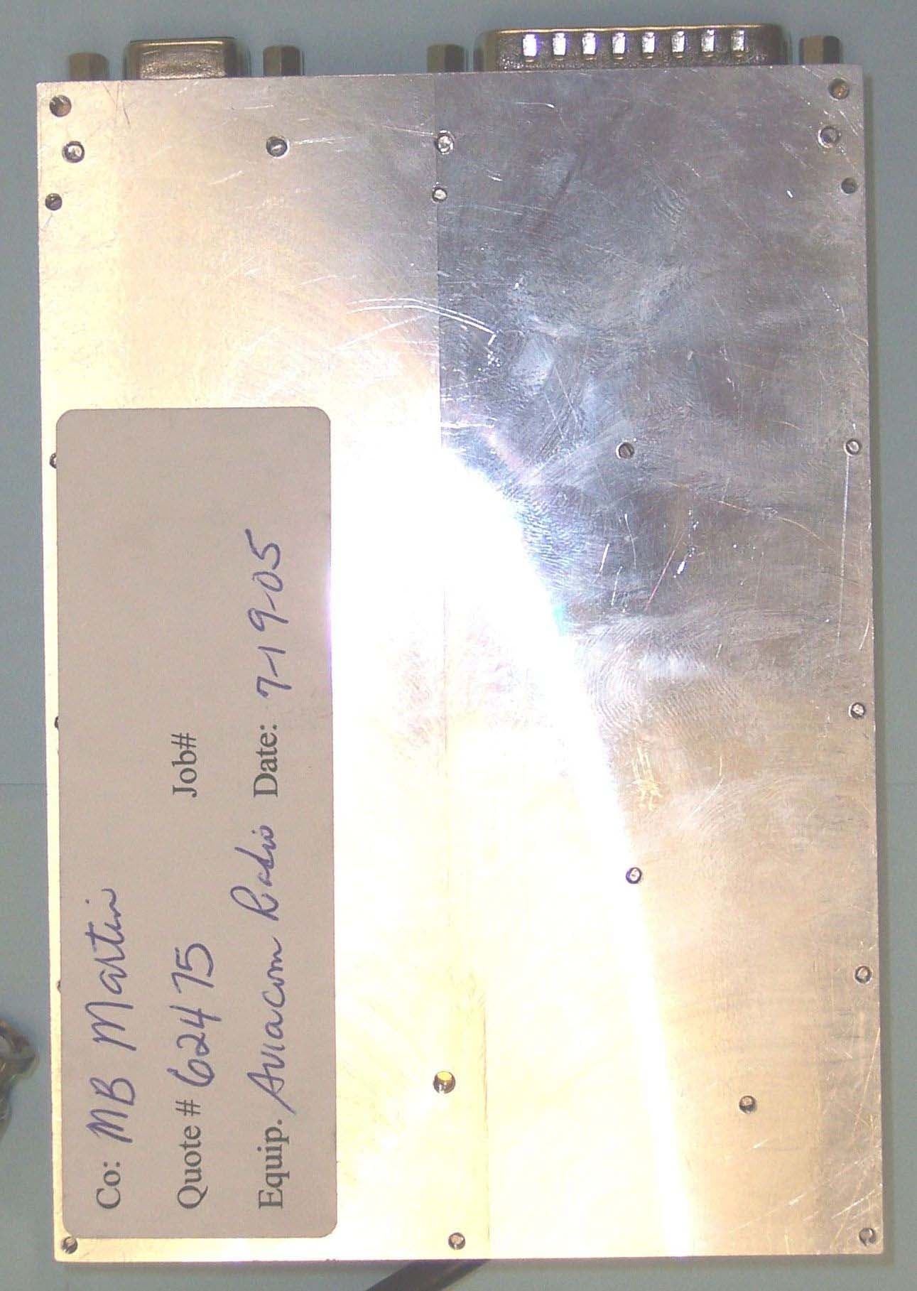
Click to zoom
Application Details
- Equipment Class
- TNB - Licensed Non-Broadcast Station Transmitter
- Date of Grant
- Oct 20, 2005
- Application Purpose
- Original Equipment
- Date of Application
- Oct 20, 2005
- Equipment Note
- VHF aviation transceiver
- Frequency Range
- 118.00000000 - 136.97500000
- Company
- MB Martin & Company
- Country
- United States
Documents & Files
Document Text
Text extracted from the exhibit documents filed with the FCC. Open a document above to read the original.
Users Manual
MB Martin AVIACOM1 VHF Aviation Transceiver User’s Guide IMPORTANT! Changes or modifications not expressly approved by the manufacture could void the user's authority to operate the equipment. INTRODUCTION The AVIACOM1 VHF aviation transceiver is intended to be used as a building block in conventional or automated air-to-ground communications systems for airports. It has been designed to survive harsh environments of temperature and electromagnetic noise (e.g., nearby personal computers, lighting systems, backup power subsystems etc.). In general, the operational qualities of this radio are orders of magnitude better than FCC requirements. Additionally, it has unique features for measuring/reporting operating parameters such as antenna quality, temperature, modulation level, receive signal strength and transmit power output. IMPORTANT! The shielding/filtering of any radio is ineffective in dealing with noise/interference which exists at the receiver’s operating frequency and is present at the antenna location. Be sure to locate the antenna an adequate distance away from such sources of interference. In rare cases, the use of double-shielded antenna transmission line may also be required to prevent on-frequency noise (other than that found near the antenna) from entering the radio. Basic operation requires: ¾ DC power (e.g., 12V battery) ¾ A source of transmit audio (e.g., microphone) ¾ A destination for received audio (e.g., amplifier/loudspeaker) ¾ An antenna One of sixteen user-programmable frequencies may be selected using an integral switch. Or ... any frequency may be selected via an RS232 serial interface. The radio is shipped with software (runs on personal computer) which may be used for test, control, and setup. All audio/power/control connections are made via a standard 25 pin male D connector. The antenna connects via a male SMB (snap-on) coaxial connector. A 9-pin female D connector is provided as an alternate way to connect to the serial port (standard IBM-PC pin assignments). Detailed performance specifications may be found at the end of this document. INTERFACE CONNECTORS IMPORTANT! There is a two-pin connector adjacent to the rotary switch. These two pins must be shorted together via a jumper block (factory installed) in order for the radio to function properly. A suitable 50 Ohm antenna should be connected to the “SMB” male coaxial connector located in a protective recess in the top cover. Peak envelope transmit output power is Approximately 1.5 Watts. When used with the MB Martin SJ-1 antenna, this level of output power provides usable two-way air-to-ground communication out to a distance of 25 nautical miles. A 25-pin male D connector is provided for DC power, audio connections and transmitter activation. DC power consumption is .110 A in receive and .4A during transmit. DB25 connector pin assignments: 1 Receive Audio (output), 1V peak-to-peak, 600 Ohms impedance 2 ground 3 Transmit audio (input), 1V peak-to-peak for 90% modulation (600 Ohms) 4 Ground 5 Microphone Bias (output) – appears during transmit for use with carbon microphone 6 Push-to-Talk (input) – connect this pin to ground to transmit 7 Squelch (output) – measures 0 Volts when received signal exceeds squelch threshold 8 test point; factory use only 9 test point; factory use only 10 +12VDC power (input) 11 +12VDC power (input) 12 ground 13 ground 14 AUX1 output (open collector) 15 AUX2 output (open collector) 16 ground 17 test point; factory use only 18 RS232 Data Out - reports and command acknowledgments from radio 19 RS232 Data In – command input from user 20 test point; factory use only 21 connects to D3 of 16-position switch 22 connects to D2 of 16-position switch 23 connects to D1 of 16-position switch 24 connects to D0 of 16-position switch 25 ground A nine-pin female D connector (a.k.a. DB9) is provided, allowing connection directly to a standard IBM-PC serial port using a simple male/female cable (i.e., null modem not required). Communications parameters are 4800 N,8,1 with no handshaking. In addition to the serial in/out lines as duplicated in the 25 pin connector, the DB9 includes additional RS232 signals. DB9 connector pin assignments: 1 Carrier Detect – goes “low” when received signal is strong enough to break squelch 2 Data Out - reports and command acknowledgments from radio 3 Data In – command input from user 4 DTR - take this line “low “ to activate transmitter (alt. To PTT and $T command) 5 GROUND 6-9 no connection CONTROL SOFTWARE Two versions of control software are included ... one will run under any DOS operating system and the other is a true 32-bit Windows application. The Windows version provides full RS232 support when using USB-to-serial adapters (the MS-DOS version also runs under Windows; however, the carrier-detect line is not supported when using a USB-to-serial adapter). Using the software you may ... ¾ assign your own frequencies to the 16 switch positions ¾ re-assign the factory defaults for the 16 switch positions ¾ list actual switch frequencies ¾ manually set any allowable frequency in the 118-136.975 MHz range ¾ read radio temperature ¾ read power supply voltage ¾ read transmit output power ¾ read transmitter modulation level ¾ read antenna VSWR (or equivalent return loss) ¾ read current received signal strength ¾ read signal strength for latest signal which un-squelched radio ¾ read radio serial number and firmware version The software is self explanatory ... so there is no need to provide instruction manual information here. FACTORY DEFAULT FREQUENCIES The default primary frequency (active frequency at power-up) is prescribed by the setting of the 16-position rotary switch located between the two D-connectors. The switch position is constantly monitored by the radio’s microprocessor ... changing the switch position while the radio is on causes an immediate frequency update. Here are the sixteen frequencies programmed at the factory: Switch position 0 122.800 MHz 1 122.7…
Text truncated - open the document above for the full version.
Users Manual
MB Martin AVIACOM1 VHF Aviation Transceiver User’s Guide IMPORTANT! Changes or modifications not expressly approved by the manufacture could void the user's authority to operate the equipment. INTRODUCTION The AVIACOM1 VHF aviation transceiver has been designed to survive harsh environments of temperature and electromagnetic noise (e.g., nearby personal computers, lighting systems, backup power subsystems etc.). It has also been designed to meet RTCA recommendations for not interfering with GPS receivers and not being jammed by FM radio broadcasts. In general, the operational qualities of this radio are orders of magnitude better than FCC requirements and RTCA recommendations. Additionally, it has unique features for measuring/reporting operating parameters such as antenna quality, temperature, modulation level, receive signal strength and transmit power output. IMPORTANT! The shielding/filtering of any radio is ineffective in dealing with noise/interference which exists at the receiver’s operating frequency and is present at the antenna location. Be sure to locate the antenna an adequate distance away from such sources of interference. In rare cases, the use of double-shielded antenna transmission line may also be required to prevent on-frequency noise (other than that found near the antenna) from entering the radio. Basic operation requires: ¾ DC power (e.g., 12V battery) ¾ A source of transmit audio (e.g., microphone) ¾ A destination for received audio (e.g., amplifier/loudspeaker) ¾ An antenna IMPORTANT! In view of radio frequency energy exposure requirements, we recommend that the minimum separation between the antenna and people be one meter. This distance represents a comfortable margin above the calculated 22 cm distance as required when using the MB Martin SJ-1 antenna (gain= 4.5 dBi). One of sixteen user-programmable frequencies may be selected using an integral switch. Or ... any frequency may be selected via an RS232 serial interface. The radio is shipped with software (runs on personal computer) which may be used for test, control, and setup. All audio/power/control connections are made via a standard 25 pin male D connector. The antenna connects via a male SMB (snap-on) coaxial connector. A 9-pin female D connector is provided as an alternate way to connect to the serial port (standard IBM-PC pin assignments). Detailed performance specifications may be found at the end of this document. INTERFACE CONNECTORS IMPORTANT! There is a two-pin connector adjacent to the rotary switch. These two pins must be shorted together via a jumper block (factory installed) in order for the radio to function properly. A suitable 50 Ohm antenna should be connected to the “SMB” male coaxial connector located in a protective recess in the top cover. Peak envelope transmit output power is Approximately 1.5 Watts. When used with the MB Martin SJ-1 antenna, this level of output power provides usable two-way air-to-ground communication out to a distance of 25 nautical miles. A 25-pin male D connector is provided for DC power, audio connections and transmitter activation. DC power consumption is .110 A in receive and .4A during transmit. DB25 connector pin assignments: 1 Receive Audio (output), 1V peak-to-peak, 600 Ohms impedance 2 ground 3 Transmit audio (input), 1V peak-to-peak for 90% modulation (600 Ohms) 4 Ground 5 Microphone Bias (output) – appears during transmit for use with carbon microphone 6 Push-to-Talk (input) – connect this pin to ground to transmit 7 Squelch (output) – measures 0 Volts when received signal exceeds squelch threshold 8 test point; factory use only 9 test point; factory use only 10 +12VDC power (input) 11 +12VDC power (input) 12 ground 13 ground 14 AUX1 output (open collector) 15 AUX2 output (open collector) 16 ground 17 test point; factory use only 18 RS232 Data Out - reports and command acknowledgments from radio 19 RS232 Data In – command input from user 20 test point; factory use only 21 connects to D3 of 16-position switch 22 connects to D2 of 16-position switch 23 connects to D1 of 16-position switch 24 connects to D0 of 16-position switch 25 ground A nine-pin female D connector (a.k.a. DB9) is provided, allowing connection directly to a standard IBM-PC serial port using a simple male/female cable (i.e., null modem not required). Communications parameters are 4800 N,8,1 with no handshaking. In addition to the serial in/out lines as duplicated in the 25 pin connector, the DB9 includes additional RS232 signals. DB9 connector pin assignments: 1 Carrier Detect – goes “low” when received signal is strong enough to break squelch 2 Data Out - reports and command acknowledgments from radio 3 Data In – command input from user 4 DTR - take this line “low “ to activate transmitter (alt. To PTT and $T command) 5 GROUND 6-9 no connection CONTROL SOFTWARE Two versions of control software are included ... one will run under any DOS operating system and the other is a true 32-bit Windows application. The Windows version provides full RS232 support when using USB-to-serial adapters (the MS-DOS version also runs under Windows; however, the carrier-detect line is not supported when using a USB-to-serial adapter). Using the software you may ... ¾ assign your own frequencies to the 16 switch positions ¾ re-assign the factory defaults for the 16 switch positions ¾ list actual switch frequencies ¾ manually set any allowable frequency in the 118-136.975 MHz range ¾ read radio temperature ¾ read power supply voltage ¾ read transmit output power ¾ read transmitter modulation level ¾ read antenna VSWR (or equivalent return loss) ¾ read current received signal strength ¾ read signal strength for latest signal which un-squelched radio ¾ read radio serial number and firmware version The software is self explanatory ... so there is no need to provide instruction manual information here. FACTORY DEFAULT FREQUENCIES The default primary frequency (active frequency at power-up) is prescribed by the se…
Text truncated - open the document above for the full version.
Cover Letter(s)
MB Martin & Company 965 Leigh Mill Road Great Falls, VA 22066 703-801-1400 August 15, 2005 American Telecommunications Certification Body, Inc. 6731 Whittier Avenue Suite C110 McLean, VA 22101 To Whom It May Concern: Please be advised that MB Martin & Company authorizes Washington Laboratories, Ltd. to act on our behalf, until otherwise notified, for applications submitted to American Telecommunications Certification Body, Inc. (ATCB). We certify that we are not subject to denial of federal benefits, that includes FCC benefits, pursuant to Section 5301 of the Anti-Drug Abuse ACT of 1988, U.S.C. 862. Further, no party, as defined in 47 CFR 1.2002(b), to the application is subject to denial of federal benefits, that includes FCC benefits. Thank you for your attention to this matter. Sincerely. James W. Mastropole V.P., Engineering
Cover Letter(s)
American Telecommunications Certification Body Inc. 6731 Whittier Ave, McLean, VA 22101 September 2, 2005 RE: FCC ID: TDOAVIACOM1_ATCB002745 Attention: Gregory M. Snyder I have a few comments on this Application. Please note that further comments may arise in response to answers provided to the questions below. 1. Please explain why ANSI C63.4 2003 is listed as a test method in the report. 2. Please note that part 87.131 lists many classes of stations. The report states the device is a ground based application while the manual states it is an air-to-ground system. Please clarify. 3. On page 13 of the test report the 100Hz modulation instantly drops at about 400mv and stays at 0. Is this due to the limiter/filter, or is this a measurement problem. Please explain. 4. Please note that on the modulation deviation plot on page 13 of the report the vertical axis is labeled “% Amplitude Modulation (KHz)”. Please explain the (kHz) notation in relation to %. 5. Please complete the frequency tolerance section of the 731. 6. Please note that the measured OBW of the device appears to be 5.83kHz. The emissions designator shown on the 731 is 6K00A3E. Please note that for a device with an authorized bandwidth of 8.33kHz the emissions designator in the table in 80.137(a) states 5K60A3E. The 6K00A3E applies to the device just above the 8.33kHz authorized BW device which would have an authorized bandwidth mentioned in note \3\ of 80.137(a). Please explain why you are using the emissions designator for a note \3\ device when the authorized bandwidth referenced in the report is 8.33kHz. Dennis Ward mailto:[email protected] The items indicated above must be submitted before processing can continue on the above referenced application. Failure to provide the requested information may result in application termination. Correspondence should be considered part of the permanent submission and may be viewed from the Internet after a Grant of Equipment Authorization is issued. Please do not respond to this correspondence using the email reply button. In order for your response to be processed expeditiously, you must submit your documents through the AmericanTCB.com website. Also, please note that partial responses increase processing time and should not be submitted. Any questions about the content of this correspondence should be directed to the sender.
Cover Letter(s)
Washington Laboratories, Ltd. 7560 LINDBERGH DRIVE GAITHERSBURG, MD 20879 (301) 417 – 0220 FAX # (301) 417 - 9069 September 7, 2005 Mr. Dennis Ward American Telecommunications Certification Body Inc. 6731 Whittier Ave McLean, VA 22101 RE: Comments of September 2, 2005 APPLICATION: TDOAVIACOM1 MB Martin and Company Dear Mr. Ward: Below are the comments that you have provided regarding the application for certification referenced above. Our responses to those comments are in bold italic. Many responses refer you to additional exhibit(s) which has been uploaded to the application folder at the ATCB website. Thank you for your attention. Please feel free to contact us for any additional information that you may require. Regards, Gregory M. Snyder Chief EMC Engineer, Wireless/Telco Services Manager Brian J. Dettling Documentation Specialist WLL Project: 8843 1) Please explain why ANSI C63.4 2003 is listed as a test method in the report. R. The reference to ANSI C63.4 is in error and has been removed from the revised test report. 2) Please note that part 87.131 lists many classes of stations. The report states the device is a ground based application while the manual states it is an air-to-ground system. Please clarify. R. The unit is for ground based applications only. The statement in the manual is to indicate that the unit is used to communicate to aircraft in flight. 3) On page 13 of the test report the 100Hz modulation instantly drops at about 400mv and stays at 0. Is this due to the limiter/filter, or is this a measurement problem. Please explain. Response to ATCB Comments FCC ID: TDOAVIACOM1 1 R. This is due to the limiter. This was noted during the measurement and therefore the setup and rechecks of this data was used to verify the results. 4) Please note that on the modulation deviation plot on page 13 of the report the vertical axis is labeled “% Amplitude Modulation (KHz)”. Please explain the (kHz) notation in relation to %. R. The “kHz” is an error and has been removed from the revised test report. 5) Please complete the frequency tolerance section of the 731. R. The 731 has been amended to show the frequency tolerance. 6) Please note that the measured OBW of the device appears to be 5.83kHz. The emissions designator shown on the 731 is 6K00A3E. Please note that for a device with an authorized bandwidth of 8.33kHz the emissions designator in the table in 80.137(a) states 5K60A3E. The 6K00A3E applies to the device just above the 8.33kHz authorized BW device which would have an authorized bandwidth mentioned in note \3\ of 80.137(a). Please explain why you are using the emissions designator for a note \3\ device when the authorized bandwidth referenced in the report is 8.33kHz. R. The emission designator has been corrected to the 5K60A3E designation. The test report and 731 have also been updated to show the correct emission designator. Response to ATCB Comments FCC ID: TDOAVIACOM1 2
Cover Letter(s)
MB Martin & Company 965 Leigh Mill Road Great Falls, VA 22066 703-801-1400 August 15, 2005 American Telecommunications Certification Body, Inc. 6731 Whittier Avenue Suite C110 McLean, VA 22101 RE: Certification Application FCC ID: TDOAVIACOM1 Please be advised that under the provision of 47 CFR 0.459 the following exhibits are to be held confidential on behalf of APPLICANT NAME: • Schematics • Operational Description • Block Diagram • Bill of Materials • Tune-up Procedure The application contains technical information that MB Martin & Company deems to be trade secrets and proprietary. If made public, the information might be used to the disadvantage of the applicant in the market place. Thank you for your attention to this matter. Sincerely, James W. Mastropole V.P, Engineering
External Photos
External Photos
ID Label/Location Info
Label and Location MB Martin & Company VHF Aviation Radio Transceiver FCC ID: TDOAVIACOM1 This device complies with FCC Rules. Operation is subject to the condition that this device does not cause harmful interference.
Internal Photos
Note: PCB is bonded to the aluminum housing. There are no traces or components on the underside.
RF Exposure Info
S= power density P= power input to the antenna G= power gain of the antenna in the direction of 2 interest relative to an isotropic radiator R= distance to the center of radiation of the antenna Choose ENTER Occupational/Controlled General Population/Uncontrolled Tx Frequency: 136.00 (MHz) Maximum Peak Power at Antenna Input Terminal: 26.200 (dBm) Antenna gain : 4.50 (dBi) S=0.2000 (mW/cm^2) P=416.869 (mW) G=2.82 (numeric) R =21.62(cm) S (mw/cm^2) at 20cm 0.233485206 OET Bulletin 65, Edition 97-01 Prediction of MPE Limit Equation from page 18 2 4R PG S π = 4 R PG S π =
Test Report
Certificates and reports shall not be reproduced except in full, without the written permission of Washington Labs, Limited. FCC Certification Test Report (Revision 1) For MB Martin & Company FCC ID: TDOAVICOM1 August 2005 Rev. 1: September 2005 Prepared for: MB Martin & Company 965 Leigh Mill Road Great Falls, VA 22066 Prepared By: Washington Laboratories, Ltd. 7560 Lindbergh Drive Gaithersburg, Maryland 20879 MB Martin & Company AVIACOM1 VHF Transceiver FCCID: TDOAVICOM1 FCC Certification Test Report August 2005 WLL Report #8843-01 - i - © 2005 Washington Laboratories, Ltd. FCC Certification Test Report (Revision 1) For the MB Martin & Company AVIACOM1 VHF Transceiver WLL JOB# 8843 August 2005 Rev. 1: September 2005 Prepared by: Christina M. Karlhoff Technical Liaison Reviewed by: Gregory M. Snyder Chief EMC Engineer MB Martin & Company AVIACOM1 VHF Transceiver FCC Certification Test Report August 2005 WLL Report #8843-01 - ii - © 2005 Washington Laboratories, Ltd. Abstract This report has been prepared on behalf of MB Martin & Company to support the attached Application for Equipment Authorization. The test report and application are submitted for a transceiver under Part 87 part of the FCC Rules and Regulations. This Federal Communication Commission (FCC) Certification Test Report documents the test configuration and test results for a MB Martin & Company AVIACOM1 VHF Transceiver. Testing was performed on an Open Area Test Site (OATS) of Washington Laboratories, Ltd, 7560 Lindbergh Drive, Gaithersburg, MD 20879. Site description and site attenuation data have been placed on file with the FCC's Sampling and Measurements Branch at the FCC laboratory in Columbia, MD. Washington Laboratories, Ltd. has been accepted by the FCC and approved by NIST NVLAP (NVLAP Lab Code: 200066-0) as an independent FCC test laboratory. The MB Martin & Company AVIACOM1 VHF Transceiver complies with the limits for a transmitter device under Part 87 part of the FCC Rules and Regulations. MB Martin & Company AVIACOM1 VHF Transceiver FCC Certification Test Report August 2005 WLL Report #8843-01 - iii - © 2005 Washington Laboratories, Ltd. Table of Contents Abstract...................................................................................................................................................... ii 1 Introduction................................................................................................................................... 1 1.1 Compliance Statement ................................................................................................................ 1 1.2 Test Scope ................................................................................................................................... 1 1.3 Contract Information................................................................................................................... 1 1.4 Test Dates ................................................................................................................................... 1 1.5 Test and Support Personnel ........................................................................................................ 1 1.6 Abbreviations .............................................................................................................................. 2 2 Equipment Under Test ................................................................................................................. 3 2.1 EUT Identification & Description .............................................................................................. 3 2.2 Test Configuration ...................................................................................................................... 3 2.3 Testing Algorithm....................................................................................................................... 4 2.4 Test Location .............................................................................................................................. 4 2.5 Measurements ............................................................................................................................. 5 2.5.1 References............................................................................................................................... 5 2.6 Measurement Uncertainty........................................................................................................... 5 3 Test Results.................................................................................................................................... 6 3.1 RF Power Output: (§2.1046(a)/§87.131) .................................................................................... 6 3.2 Modulation Characteristics: (FCC Part 87 §2.1047(a)/§87.141); Audio Filter Response and Modulation Limiting............................................................................................................................... 7 3.3 Emission Mask and Occupied Bandwidth: (FCC Part §2.1049/§87.139(a))............................ 10 3.4 Spurious Emissions at Antenna Terminals (FCC §87.139(a) and §2.1051)............................. 15 3.5 Radiated Spurious Emissions: (FCC Part 87 and §2.1053) ...................................................... 25 3.5.1 Test Procedure.................................................................................................................... 25 3.6 Frequency Stability: (FCC Part §2.1055/§87.133) ................................................................... 29 MB Martin & Company AVIACOM1 VHF Transceiver FCC Certification Test Report August 2005 WLL Report #8843-01 - iv - © 2005 Washington Laboratories, Ltd. List of Tables Table 1. Device Summary........................................................................................................................... 3 Table 2. RF Power Output ........................................................................…
Text truncated - open the document above for the full version.
Test Report
DB[E21] -60 -55 -50 -45 -40 -35 -30 -25 -20 -15 -10 -5 0 Freq (KHz) 0 2 4 6 8 10 12 14 16 18 20 AVCOM1 TX AUDIO FILTER AVCOM1 TX AUDIO FILTER
Test Report
Date: 8/5/2005 Time: 11:53:50 AM AVIACOM1 modulation frequency response TX audio input is white noise 6dB above 90% AM level; RF output applied to HP diode detector and Stanford Research SR-7 70 audio network analyzer
Contact Information
Applicant
James Ward Mastropole(co-owner/director of engineering)
Technical Contact
Washington Laboratories, Ltd.Gregory Snyder
7560 Lindbergh Drive · Gaithersburg, Maryland · United States
Technical Specifications
| # | Rule Parts | Frequency Range | Power Output | Emission | Tolerance |
|---|---|---|---|---|---|
| 1 | 87 | 118 MHz - 136.975 MHz | 419.80 mW | 5K6A3E | 20.0000000000 ppm |