TF7WT-42-1000Wireless Thermostat
Everex Communications, Inc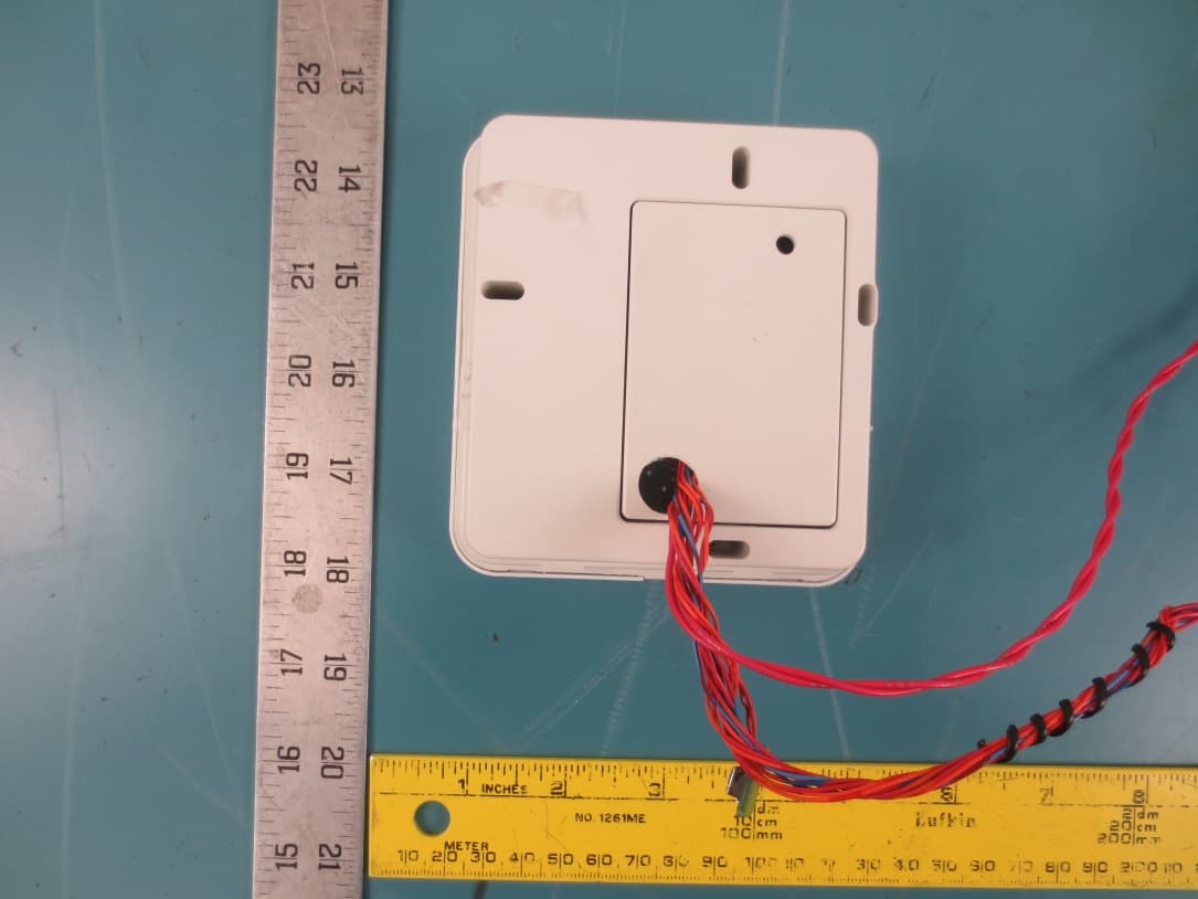
Click to zoom
Application Details
- Equipment Class
- DTS - Digital Transmission System
- Date of Grant
- Jan 30, 2020
- Application Purpose
- Original Equipment
- Date of Application
- Jan 30, 2020
- Equipment Note
- Wireless Thermostat
- Frequency Range
- 2405.00000000 - 2480.00000000
- Company
- Everex Communications, Inc
- Country
- United States
Documents & Files
Document Text
Text extracted from the exhibit documents filed with the FCC. Open a document above to read the original.
Users Manual
Everex Communications, Inc WT-42 User’s Manual: WT-42 is a wired thermostat, with optional remote management capability, which controls the setting of a Heating/Air Conditioning/Ventilation Heating (HVAC) unit based on user’s inputs. The thermostat consists of a LCD display which shows the current setting to the user, an occupancy sensor which detects the state of occupancy and 4 buttons for user’s setting. The unit is powered from a 24VAC Class 2 transformer. There are 4 buttons on the unit, namely MODE, FAN, Up Arrow and Down Arrow. The following are the functions of these buttons. MODE – To select OFF, HEAT or COOL mode. FAN – To change the fan speed to HIGH speed or LOW speed setting or AUTO. UP Arrow/DOWN Arrow – To increase (Up) or decrease (Down) temperature setting. Installation Switch off the power to the 24VAC transformer. Pull the plastic front cover from the base plate. Mount the base plate onto the wall, about 5 feet from the ground, where the thermostat has good circulation of air, and is not in direct sunlight or near any heat source. Route the wirings from the wall through the base plate opening and connect them to the screw terminal on the back side of the thermostat as shown in the following figures, depending on your HVAC configuration. Switch on the power to the transformer. If there is a remote management network, press the SETUP button next to the screw terminal to initiate the binding process to the network. Install the thermostat back onto the base plate. Note: This equipment has been tested and found to comply with the limits for a Class B digital device, pursuant to Part 15 of the FCC Rules. These limits are designed to provide reasonable protection against harmful interference in a residential installation. This equipment generates, uses and can radiate radio frequency energy and, if not installed and used in accordance with the instructions, may cause harmful interference to radio communications. However, there is no guarantee that interference will occur in a particular installation. If this equipment does cause harmful interference to radio or television reception, which can be determined by turning the equipment off and on, the user is encouraged to try to correct the interference by on or more of the following measures: - Reorient or relocate the receiving antenna. - Increase the separation between the equipment and receiver. - Consult the dealer or an experienced radio/TV technician for help. Caution: This equipment is authorized for use under the United States Federal Communication Commission Rules and Regulations, Code of Federal Regulations Chapter 47 part 15 and must be installed in accordance with the instructions provided in this document. Failure to install or operate this equipment as instructed in this document could void the user’s authority to operate the equipment. This equipment contains no user serviceable parts. Any modification or repairs to the internal components or to the antenna configuration of the equipment without the express written consent of Everex Communications, Inc. could void the user’s authority to operate the equipment. NOTE: TO COMPLY WITH FCC RF EXPOSURE REQUIREMENTS IN SECTION 1.1307, A MINIMUM SEPARATION DISTANCE OF 20CM (8 INCHES) IS REQUIRED BETWEEN THE EQUIPMENT AND ALL PERSONS. Copyright © 2020 Everex Communications, Inc. Everex Communications, Inc. reserves the right to change the content of this user’s manual without notification
Cover Letter(s)
QA-FR-172-A FCC Confidential Authorization 2019/11/25 FEDERAL COMMUNICATIONS COMMISSIONS Authorization and Evaluation Division 7435 Oakland Mills Road Columbia, MD 21046 Subject: Confidentiality Request regarding application for certification of FCC ID: TF7WT-42-1000 In accordance with Sections 0.457 and 0.459 of the Commission’s Rules, Everex Communications, Inc. hereby requests long-term confidential treatment of information accompanying this application as outlined below: Block Diagram Schematics Operation Description As well as short-term (45 days) confidential treatment of information accompanying this application as outlined below: Internal Photos User’s Manual External Photos Test Set-up Photos The above materials contain proprietary and confidential information not customarily released to the public. The public disclosure of these materials provides unjustified benefits to its competitors in the market. Sincerely, Vincent Chan 1045 Mission Court, Fremont, CA 94539
External Photos
Everex Communications, Inc. FCC ID: TF7WT-42-1000 EUT External Photographs 1.1 EUT – Thermostat Top View 1.2 EUT – Thermostat Bottom View Everex Communications, Inc. FCC ID: TF7WT-42-1000 1.3 EUT – Thermostat Front View 1.4 EUT – Thermostat Rear View Everex Communications, Inc. FCC ID: TF7WT-42-1000 1.5 EUT – Thermostat Right Side View 1.6 EUT – Thermostat Left Side View
ID Label/Location Info
Label and Label Location EUT Bottom
Internal Photos
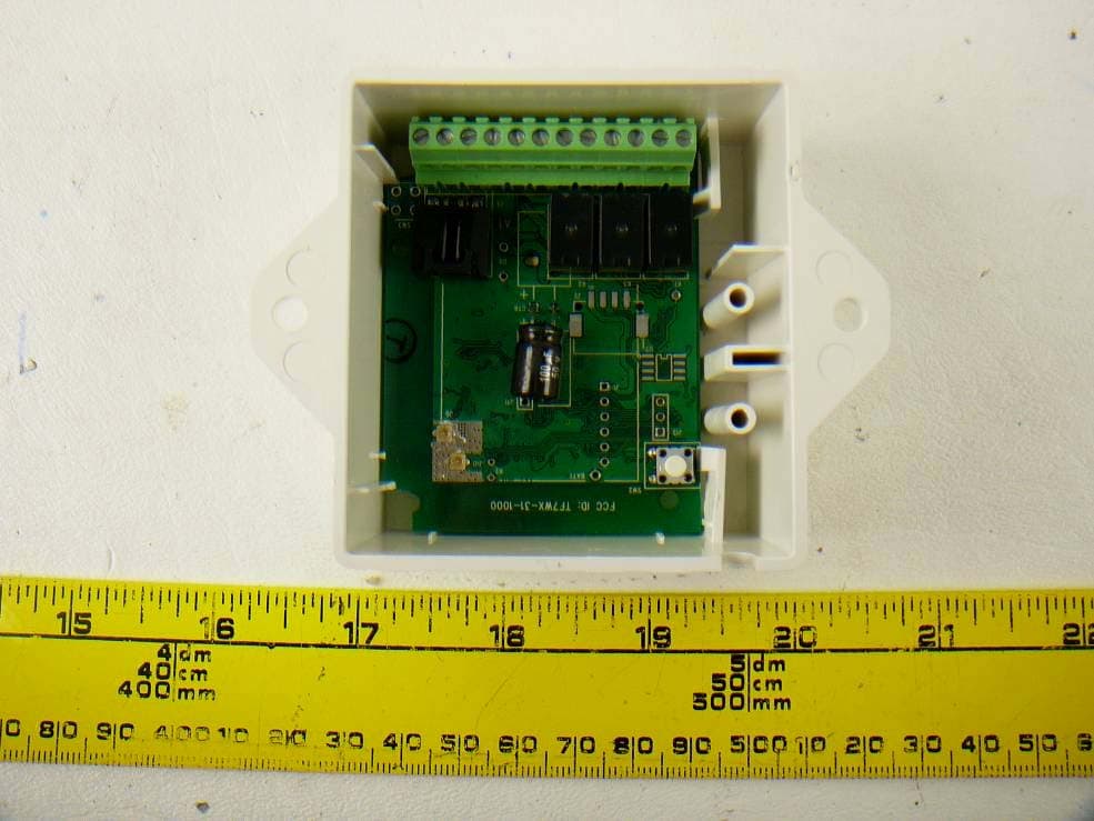
Everex Communications, Inc. FCC ID: TF7WT-42-1000 Annex C (Normative) - EUT Internal Photographs 1.1 EUT – Thermostat Internal PCB Top View 1.2 EUT – Thermostat Internal PCB Bottom View RF Antenna Pre‐certified module
Test Report
Note: This test report is prepared for the customer shown above and for the device described herein. It may not be duplicated or used in part without prior written consent from Bay Area Compliance Laboratories Corp. This report must not be used by the customer to claim product certification, approval, or endorsement by A2LA*, NIST, or any agency of the Federal Government. * This report may contain data that are not covered by the A2LA accreditation and are marked with an asterisk “*” (Rev.2) FCC PART 15, SUBPART C TEST REPORT For Everex Communications, Inc. 1045 Mission Ct., Fremont, CA 94539, USA FCC ID: TF7WT-42-1000 Report Type: Original Report Product Type: HVAC Thermostat Prepared By: Christian McCaig Test Engineer Report Number: R1906281-247 Report Date: 2019-11-23 Reviewed By: Frank Wang RF Lead Bay Area Compliance Laboratories Corp. 1274 Anvilwood Avenue, Sunnyvale, CA 94089, USA Tel: (408) 732-9162, Fax: (408) 732-9164 Everex Communications, Inc. FCC ID: TF7WT-42-1000 Report Number: R1906281-247 Page 2 of 42 FCC Part 15C Test Report TABLE OF CONTENTS 1 General Description ..................................................................................................................................................... 5 1.1 Product Description for Equipment Under Test (EUT) ...................................................................................... 5 1.2 Objective ............................................................................................................................................................. 5 1.3 Related Submittal(s)/Grant(s) ............................................................................................................................. 5 1.4 Test Methodology ............................................................................................................................................... 5 1.5 Measurement Uncertainty ................................................................................................................................... 5 1.6 Test Facility Registrations .................................................................................................................................. 6 1.7 Test Facility Accreditations ................................................................................................................................ 6 2 System Test Configuration.......................................................................................................................................... 9 2.1 Justification ......................................................................................................................................................... 9 2.2 Duty Cycle .......................................................................................................................................................... 9 2.3 Interface Ports and Cabling ............................................................................................................................... 10 3 Summary of Test Results ............................................................................................................................................ 11 4 FCC §15.203 - Antenna Requirements ...................................................................................................................... 12 4.1 Applicable Standards ........................................................................................................................................ 12 4.2 Antenna Description ......................................................................................................................................... 12 5 FCC §2.1091, §15.247 (i) - RF Exposure .................................................................................................................... 13 5.1 Applicable Standards ........................................................................................................................................ 13 5.2 MPE Prediction ................................................................................................................................................. 13 3.1 MPE Results ..................................................................................................................................................... 13 3.2 Radio Co-location ............................................................................................................................................. 13 6 FCC §15.207 - AC Line Conducted Emissions .......................................................................................................... 14 6.1 Applicable Standards ........................................................................................................................................ 14 6.2 Test Setup ......................................................................................................................................................... 14 6.3 Test Procedure .................................................................................................................................................. 14 6.4 Corrected Amplitude and Margin Calculation .................................................................................................. 15 6.5 Test Setup Block Diagram ................................................................................................................................ 15 6.6 Test Equipment List and Details ....................................................................................................................... 16 6.7 Test Environmental Conditions ........................................................................................................................ 16 6.8 Summary of Test Results .................................................................................................................................. …
Text truncated - open the document above for the full version.
Test Setup Photos
Everex Communications, Inc. FCC ID: TF7WT-42-1000 EUT Test Setup Photographs 1.1 Below 1GHz Front View 1.2 Below 1GHz Rear View Everex Communications, Inc. FCC ID: TF7WT-42-1000 1.3 Above 1GHz Front View 1.4 Above 1GHz Rear View Everex Communications, Inc. FCC ID: TF7WT-42-1000 1.5 AC Line Front View 1.6 AC Line Side View
Contact Information
Applicant
Vincent Chan(Engineering Director)
Test Firm
Bay Area Compliance Laboratories Corp.Lisa Tang
Technical Specifications
| # | Rule Parts | Frequency Range | Power Output |
|---|---|---|---|
| 1 | 15C | 2.40 GHz - 2.48 GHz | 23.00 mW |
Other Applications from Everex Communications, Inc
TF7WX-31-1000
Apr 15, 2013Digital Analog 2.4 GHz Wireless Controller
Equipment Class
DTS - Digital Transmission SystemTF7WR-11-1000
Sep 18, 2005802.15.4 2.4GHz Wireless Transceiver
Equipment Class
DTS - Digital Transmission System