TFF-FR-100FlexiRadio FR100
CelPlan Technologies, Inc.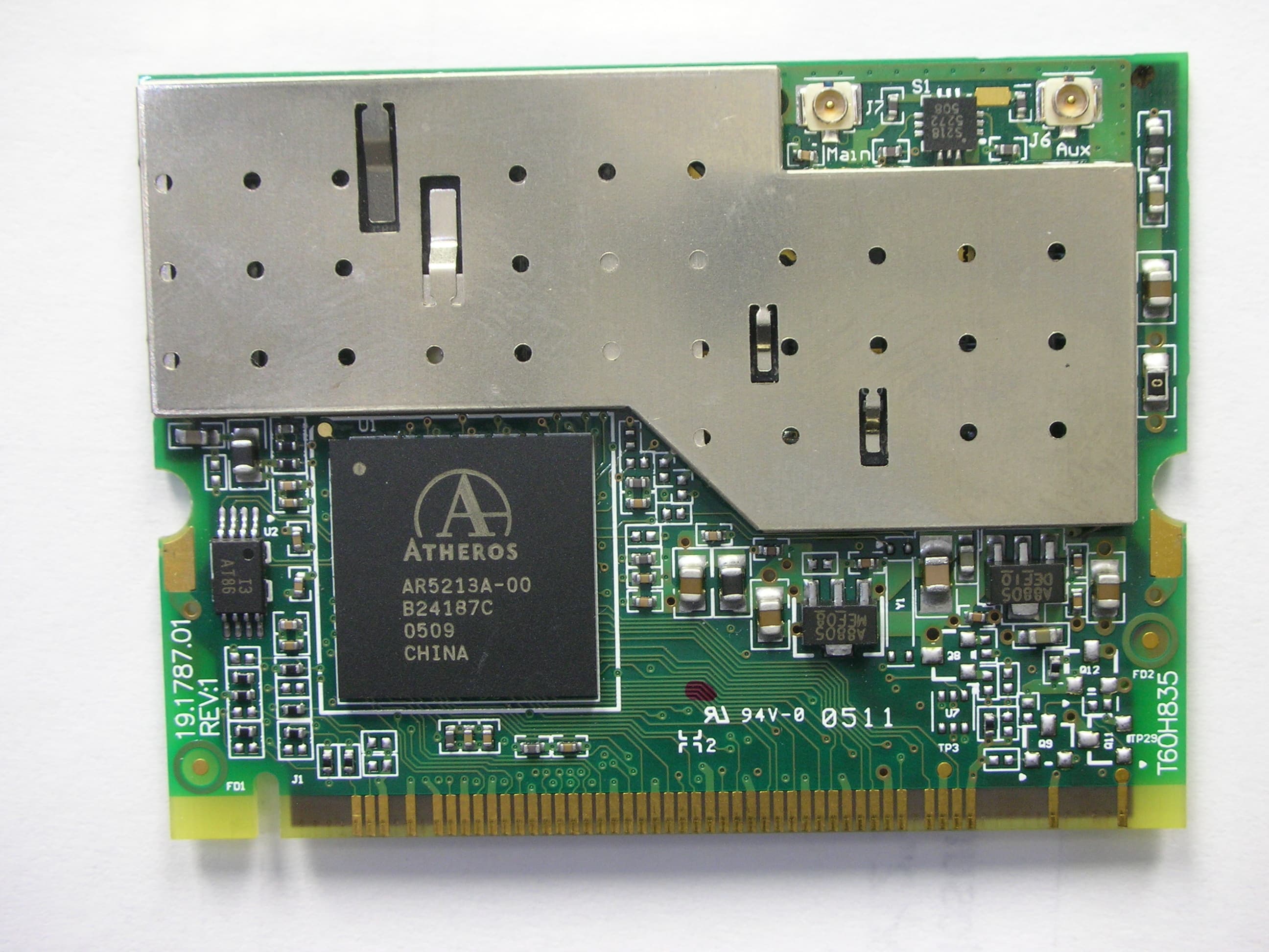
Click to zoom
Application Details
- Equipment Class
- NII - Unlicensed National Information Infrastructure TX
- Date of Grant
- Mar 08, 2008
- Application Purpose
- Original Equipment
- Date of Application
- Mar 08, 2008
- Equipment Note
- FlexiRadio FR100
- Frequency Range
- 5180.00000000 - 5240.00000000
- Company
- CelPlan Technologies, Inc.
- Country
- United States
Documents & Files
Document Text
Text extracted from the exhibit documents filed with the FCC. Open a document above to read the original.
Users Manual
WI4NET FlexiRadio FR100 Users Guide WI4NET FlexiRadio Users Guide Revision History Revision Desrription Date 1.1 Initial release June 07 © Wi4Net 1835 Alexander Bell Drive• Suite 200 Phone 703.259.4047 • Fax 703.476.8964 i Table of Contents CONDITIONS OF USE: .........................................................................................................................................................II EQUIPMENT DESCRIPTION ............................................................................................................................................... 1 AN INTRODUCTION TO FLEXIRADIO....................................................................................................................................... 1 FLEXIRADIO ENCLOSURES...................................................................................................................................................... 2 Energy Enclosure................................................................................................................................................................ 2 Radio Enclosure.................................................................................................................................................................. 2 RF Head Enclosure............................................................................................................................................................. 3 Antenna Enclosure .............................................................................................................................................................. 3 FLEXIRADIO MODELS............................................................................................................................................................. 3 General Characteristics...................................................................................................................................................... 4 NETWORK ARCHITECTURE...................................................................................................................................................... 4 Single Level Hierarchical Network .................................................................................................................................... 4 Two-Level Hierarchical Network ....................................................................................................................................... 5 Three-Level Hierarchical Network..................................................................................................................................... 5 Cross-Level Hierarchical Network..................................................................................................................................... 5 Combined Hierarchical Network........................................................................................................................................ 6 SOFTWARE STRUCTURE .................................................................................................................................................... 7 ACCESS POINT WEB SERVER.................................................................................................................................................. 8 Accessing the Web Server ................................................................................................................................................... 8 Configuration Pages .........................................................................................................................................................11 System Configuration Page ..........................................................................................................................................11 Radio Initial Setup Page ...............................................................................................................................................12 Radio Settings Page ......................................................................................................................................................13 QoS Configuration Page ...............................................................................................................................................15 Advanced Radio Settings Page .....................................................................................................................................16 Security Settings................................................................................................................................................................18 WPA Configuration Page .............................................................................................................................................18 Security Settings Page ..................................................................................................................................................19 RADIUS Security Server Configuration Page .............................................................................................................20 ACL Configuration Pages.............................................................................................................................................21 Script Configuration .........................................................................................................................................................23 Firmware Update Configuration ......................................................................................................................................24 Statistics Window..............................................................................................................................................................26 ACRONYMS ...................................................................................…
Text truncated - open the document above for the full version.
Attestation Statements
March 4, 2008 Mr. Dennis Ward American Telecommunications Certification Body Inc. 6731 Whittier Ave McLean, VA 22101 RE: Comments Regarding Conditions of Use APPLICATION: TFF-FR-100 Celplan Dear Mr. Ward: In reference to the above application, this letter is to attest that the Celplan, the Grantee, will control the configuration of the radio to only allow operation of the 5.2GHz UNII band for indoor applications and operation. Thank you for your attention. Please feel free to contact us for any additional information that you may require. Sincerely, Leonhard Korowajczuk CEO/CTO CelPlan Technologies, Inc. 1835 Alexander Bell Dr., Suite 200 Reston, VA 20191 Tel. 703 259 4020 Fax 703 476 8964
Cover Letter(s)
Request for Confidentiality Date 5/17/2007 American Telecommunications Certification Body, Inc. 6731 Whittier Avenue Suite C110 McLean, VA 22101 RE: Certification Application FCC ID: TFF-FR-100 Please be advised that under the provision of 47 CFR 0.459 the following exhibits are to be held confidential on behalf of CelPlan Technologies Inc: • Schematics • Bill of Materials • Operational Description • Block Diagram • Tune-up Procedure The application contains technical information that CelPlan Technologies deems to be trade secrets and proprietary. If made public, the information might be used to the disadvantage of the applicant in the market place. Thank you for your attention to this matter. Leonhard Korowajczuk CEO/CTO CelPlan Technologies, Inc. CelPlan Technologies, Inc. 1897 Preston White Drive suite 300 Reston VA 20191USA Tel: 1-703-259-4022 Fax: 1-703-476-8964 www.celplan.com www.wi4net.com
Cover Letter(s)
December 5, 2006 To Whom It May Concern: Please be advised that CelPlan Technologies, Inc. authorizes Washington Laboratories, Ltd. to act on our behalf, until otherwise notified, for applications submitted to American Telecommunications Certification Body, Inc. (ATCB). We certify that we are not subject to denial of federal benefits that includes FCC benefits, pursuant to Section 5301 of the Anti-Drug Abuse ACT of 1988, U.S.C. 862. Further, no party, as defined in 47 CFR 1.2002(b), to the application is subject to denial of federal benefits, that includes FCC benefits. Thank you for your attention to this matter. Sincerely, Leonhard Korowajczuk CelPlan Technologies, Inc. CelPlan Technologies, Inc. 1835 Alexander Bell Dr., Suite 200 Reston, VA 20191 Tel. 703 259 4020 Fax 703 476 8964
Cover Letter(s)
August 17, 2007 «Subject: Modular Approval Request » FCC ID: TFF-FR-100 CelPlan Technologies Inc. FR100, FCC ID: TFF-FR-100, would like to have your authorization as a modular approval. The requirements of Public Notice DA00-1407 have been met and shown on the following statements. 1. “The modular transmitter must have its own RF shielding.” The radio portion of this module has been shielded, please see exhibition External Photo. 2. “The modular transmitter must have buffered modulation/data inputs.” The FR100 contains buffered data inputs; it is integrated in AR5213 MAC/Baseband Processor. 3. “The modular transmitter must have its own power supply regulation.” The FR100 contains a regulator in the DC input port, the device has an internal 2.5V power regulator (AME8805DEFT, AME8805MEFT) and a 3.3 V Host Supply. 4. “The modular transmitter must comply with the antenna requirements of section 15.203 and 15.204(C).” The FR100 has a unique u.FL(v)-LP-040 antenna connector and meets the FCC antenna requirements. The spurious emission, unique antenna connector and photo of antennas are shown in the application exhibits. 5. “The modular transmitter must be tested in a stand-alone configuration” The FR100 was tested in a stand-alone configuration via a PCMCIA adapter card. Please see exhibit “Test Setup Photos”. 6. “The modular transmitter must be labeled with its own FCC ID number.” Please see exhibit “FCC Label” for the FCC ID of this module. 7. “The modular transmitter must comply with any specific rule or operating requirements applicable to the transmitter and the manufacturer must provide adequate instructions along with the module to explain any such requirements.” The FR100 is compliant with all applicable FCC rules. Detail instructions for maintaining compliance are given in the Users Manual. 8. “The modular transmitter must comply with any applicable RF exposure requirements.” The EUT is compliant with all applicable RF exposure requirements. RF Exposure is addressed in the exhibit “MPE Data”. Please contact me if you have any further questions. Thank you for your attention. Sincerely, Leonhard Korowajczuk CelPlan Technologies, Inc. 1835 Alexander Bell Drive #200 Reston VA 20191-4324 USA Tel: 1-703-259-4022 Fax:1-703-476-8964 [email protected] CelPlan Technologies, Inc. 1835 Alexander Bell Dr., Suite 200 Reston, VA 20191 Tel. 703 259 4020 Fax 703 476 8964
Cover Letter(s)
American Telecommunications Certification Body Inc. 6731 Whittier Ave, McLean, VA 22101 May 27, 2007 RE: FCC ID: TFF-FR-100_ATCB004943 Attention: Brian Dettling I have a few comments on this Application. Please note that further comments may arise in response to answers provided to the questions below. 1. Please note that this both a modular approval under Part 15 and a licensed transmitter module under part 90. As such please provide the required part 15 modular approval letter verifying all 8 modular requirements. If this the module does not meet all of the 8 requirements for part 15 modular approval, please provide a LMA request stating the conditions for approval. 2. Please note that as this appears to be a modular approval for part 15 and a licensed modular transmitter for part 90, please provide a manual that provides the required “Contains FCC ID:zxxxxx” statement as appropriate. If this statement is in the existing manual, please point to the page number of the manual. 3. Please explain and verify how this device uses non-standard antenna(s) for the part 15 device. If this device uses standard antenna(s), please note that the manual needs to state that the antenna for aprt 15 are professionally installed. 4. Please note that the part 15 test report states testing was done to DA00705. Please note that DA00705 is for frequency hopping spread spectrum devices. Please make reference to the proper DTS test procedures approved by the FCC. Please verify the all testing was performed to the proper test methods approved by the FCC. 5. Please note that the frequency range 5725-5850 should only be certified under one rule part. Please explain why frequencies in the 5725-5825MHz range are trying to be certified under both 15.247 and 15.407. Please apply for certification under one or the other rule part. 6. Please explain what “Emission Bandwidth dB” in table 7 on page 24 of the report means. Please explain what 74dB bandwidth means. 7. Please explain how you can have a 75MHz occupied bandwidth (see page 55 of the report) and be compliant at the band edge frequency 5725MHz on a fundamental of 5745MHz (see page 53 of the report). As it is unlikely that this device has a 75MHz bandwidth as stated in the table on pages 24 and 53), please provide a bandwidth plot of the 5745MHz center frequency. 8. Please note that the manual states the uses of this device include “CityWiNet”, “Office WiNet” and HomeWiNet. Please explain how Part 90M (Dedicated Short-Range Communications Service) fits into these network systems. 9. Please note that 90M for Road Side Units has two limits. The one limit is the max power out and the other is the max allowed EIRP. Please show how the highest gain antenna used for this band meets the allowable max EIRP. 10. Please note that part 90 licensed device spurious emissions are ERP limits. Please explain why the part 90 report compares part 90 spurious emissions for this device to class B part 15 limits. Please use the correct limits and test methods for licensed device spurious emissions. 11. Please note that depending on the responses to the above, further questions may arise. Dennis Ward mailto:[email protected] The items indicated above must be submitted before processing can continue on the above referenced application. Failure to provide the requested information may result in application termination. American Telecommunications Certification Body Inc. 6731 Whittier Ave, McLean, VA 22101 August 28, 2007 RE: FCC ID: TFF-FR-100_ATCB004943 Attention: Brian Dettling Comment addendum I have a few comments on this Application. Please note that further comments may arise in response to answers provided to the questions below. 1. Please note that 90M for Road Side Units has two limits. The one limit is the max power out and the other is the max allowed EIRP. Please show how the highest gain antenna used for this band meets the allowable max EIRP. 2. Please note that part 90 M in this frequency range mentions two types of operating devices. One is the Roadside Unit (RSU). This is a DSRC transceiver that is mounted along a road or pedestrian passageway. An RSU may also be mounted on a vehicle or is hand carried, but it may only operate when the vehicle or hand-carried unit is stationary. Furthermore, an RSU operating under this part is restricted to the location where it is licensed to operate. However, portable or hand-held RSUs are permitted to operate where they do not interfere with a site-licensed operation. A RSU broadcasts data to OBUs or exchanges data with OBUs in its communications zone. An RSU also provides channel assignments and operating instructions to OBUs in its communications zone, when required. This is a part 90M device. The second is the On Board Unit (OBU). This is a DSRCS transceiver that is normally mounted in or on a vehicle, or which in some instances may be a portable unit. An OBU can be operational while a vehicle or person is either mobile or stationary. The OBUs receive and contend for time to transmit on one or more radio frequency (RF) channels. Except where specifically excluded, OBU operation is permitted wherever vehicle operation or human passage is permitted. The OBUs mounted in vehicles are licensed by rule under part 95 of this chapter and communicate with Roadside Units (RSUs) and other OBUs. Portable OBUs are also licensed by rule under part 95 of this chapter. OBU operations in the Unlicensed National Information Infrastructure (UNII) Bands follow the rules in those bands. The definition of this module as described in the manual would seem to indicate that this is not an RSU but would be an OBU. I say not an RSU because according to the definition of an RSU it must be stationary to operate and it must only operate in locations in which it is licensed. The places in which this device is described for use (i.e. laptops etc) appear to make this a portable device when used and it is not restricted to stationary use nor is it restricted t…
Text truncated - open the document above for the full version.
External Photos
Front of FR100 Back of FR100
ID Label/Location Info
PROPOSED FCC ID LABEL AND LOCATION This device complies with Part 15 of the FCC Rules. Operation is subject to the following two conditions: (1) this device may not cause harmful interference, and (2) this device must accept any interference received, including interference that may cause undesired operation. FCC ID: TFF-FR-100 PROPOSED FCC ID LABEL LOCATION
RF Exposure Info
Document 9218-MPE FCC ID: TFF-FR-100 RF Exposure Test Report Washington Laboratories, Ltd January 2008 Maximum Permissible Exposure Evaluation for CELPLAN TECHNOLOGIES, INC. FR-100 For Part 15 Certification FCC ID: TFF-FR-100 April 11, 2007 Revised January 22, 2008 WLL PROJECT #: 9218 This report may not be reproduced, except in full, without the prior written consent of Washington Laboratories, Ltd. RF Exposure Evaluation Document 9148-MPE FCC ID: TFF-FR-100 RF Exposure Test Report Washington Laboratories, Ltd January 2008 1 Maximum Permissible Exposure Test Report for FCC ID: TFF-FR-100 1 1.0 Introduction This report has been prepared on behalf of CELPLAN TECHNOLOGIES, INC. Transmitter to show compliance with the RF exposure requirements as defined in FCC §1.1307. 1.1 1.1 Requirements Three different categories of transmitters are defined by the FCC in OET Bulletin 65. These categories are fixed installation, mobile, and portable and are defined as follows: Fixed Installations: fixed location means that the device, including its antenna, is physically secured at a permanent location and is not able to be easily moved to another location. Additionally, distance to humans from the antenna is maintained to at least 2 meters. Mobile Devices: a mobile device is defined as a transmitting device designed to be used in other than fixed locations and to be generally used in such a way that a separation distance of at least 20 centimeters is normally maintained between the transmitter's radiating structures and the body of the user or nearby persons. Transmitters designed to be used by consumers or workers that can be easily re-located, such as a wireless modem operating in a laptop computer, are considered mobile devices if they meet the 20 centimeter separation requirement. The FCC rules for evaluating mobile devices for RF compliance are found in 47 CFR §2.1091. Portable Devices: a portable device is defined as a transmitting device designed to be used so that the radiating structure(s) of the device is/are within 20 centimeters of the body of the user. Portable device requirements are found in Section 2.1093 of the FCC's Rules (47 CFR§2.1093). For this test report the CELPLAN TECHNOLOGIES, INC. FR-100 is evaluated as a Modular Approval to be employed in fixed and mobile installations. The FCC also categorizes the use of the device as based upon the user’s awareness and ability to exercise control over his or her exposure. The two categories defined are Occupational/ Controlled Exposure and General Population/Uncontrolled Exposure. These two categories are defined as follows: Document 9148-MPE FCC ID: TFF-FR-100 RF Exposure Test Report Washington Laboratories, Ltd January 2008 2 Occupational/Controlled Exposure: In general, occupational/controlled exposure limits are applicable to situations in which persons are exposed as a consequence of their employment, who have been made fully aware of the potential for exposure and can exercise control over their exposure. This exposure category is also applicable when the exposure is of a transient nature due to incidental passage through a location where the exposure levels may be higher than the general population/uncontrolled limits, but the exposed person is fully aware of the potential for exposure and can exercise control over his or her exposure by leaving the area or by some other appropriate means. Awareness of the potential for RF exposure in a workplace or similar environment can be provided through specific training as part of a RF safety program. If appropriate, warning signs and labels can also be used to establish such awareness by providing prominent information on the risk of potential exposure and instructions on methods to minimize such exposure risks. General Population/Uncontrolled Exposure: The general population / uncontrolled exposure limits are applicable to situations in which the general public may be exposed or in which persons who are exposed as a consequence of their employment may not be made fully aware of the potential for exposure or cannot exercise control over their exposure. Members of the general public would come under this category when exposure is not employment-related; for example, in the case of a wireless transmitter that exposes persons in its vicinity. Warning labels placed on low-power consumer devices such as cellular telephones are not considered sufficient to allow the device to be considered under the occupational/controlled category, and the general population/uncontrolled exposure limits apply to these devices. Since there are no warnings or training associated with this unit and it can be used by anyone, the CELPLAN TECHNOLOGIES, INC. is evaluated to the General Population/Uncontrolled Exposure limits. 1.2 Radio Frequency Radiation Exposure Evaluation The highest RF output power of the unit was measured is recorded. According to §1.1310 of the FCC rules, the power density limit for General Population/Uncontrolled Exposure is 1mW/cm 2 . The MPE shall be calculated at 20cm to show compliance with the power density limit. The following formula was used to calculate the Power Density: 2 4R PG S π = Where: S = Power Density P = Output Power at the Antenna Terminals G = Gain of Transmit Antenna (linear gain-isotropic) R = Distance from Transmitting Antenna Document 9148-MPE FCC ID: TFF-FR-100 RF Exposure Test Report Washington Laboratories, Ltd January 2008 3 1.2.1 Maximum Output Power Measured Maximum Output Power dBm DTS: 2400 - 2483.5 MHz 5725 - 5850 MHz UNII: 5150-5250 MHz 5725-5825 MHz 28.2 26.0 17.0 25.1 1.2.2 Antennas Employed In Fixed Installations Following are data on the antennas to be used in the system: Type 2.4 GHz 5.2 GHz 5.3 GHz 5.8 GHz Omni Mfgr Hyperlink Hyperlink Hyperlink Hyperlink Model HG2415U/PRO HG5310U HG5310U HG5812U/PRO Gain (dBi) 15 10 10 12 Panel (patch) Mfgr Hyperlink Hyperlink Hyperlink Hyperlink Model HG2418P HG4953P HG4953P HG5158P Gain (dBi) 18 8 8 8 Directiona…
Text truncated - open the document above for the full version.
Test Report
Document 9148-01, Rev. 0 FCC ID: TFF-FR-100 FCC Certification Test Report Washington Laboratories, Ltd March 2007 FCC Test Report for CelPlan Technologies, Inc. FR-100 Flexi-Radio FCC ID: TFF-FR-100 March 30, 2007 Revised: January 14, 2008 Prepared for: CelPlan Technologies, Inc. 1835 Alexander Bell Drive Suite 200 Reston, VA 20191 Prepared By: Washington Laboratories, Ltd. 7560 Lindbergh Drive Gaithersburg, Maryland 20879 FCC Certification Test Report Document 9148-01, Rev. 0 FCC ID: TFF-FR-100 FCC Certification Test Report Washington Laboratories, Ltd March 2007 FCC Certification Test Report for the CelPlan Technologies, Inc. FR-100 Flexi-Radio FCC ID: TFF-FR-100 March 30, 2007 WLL JOB# 9148 Prepared by: Michael F. Violette President Reviewed by: Steve Koster EMC Operations Manager Document 9148-01, Rev. 0 FCC ID: TFF-FR-100 FCC Certification Test Report Washington Laboratories, Ltd February 2007 ii Abstract This report has been prepared on behalf of CelPlan Technologies, Inc. to support the attached Application for Equipment Authorization. The CelPlan Technologies, Inc. FR-100 Flexi-Radio complies with the limits for a Transmitter device under FCC Part 15E. Composite Application This report is one part of a two-part composite application for the FR-100 radio. The equipment described herein will also be authorized under Part 90 of the FCC Rules for operation in the 4940-4990 MHz band and the 5850-5925 band for licensed operation. A separate report has been prepared to document the testing for the licensed operation. Modular Approval This application is for a Modular Approval under the provisions of DA 00-1407. The FR- 100 transmitters that can be installed in CelPlan-configured systems as well as marketed to other assemblers as a Modular Approval. The test report and application are submitted for a Transmitter under Part 15E of the FCC Rules and Regulations. This Certification Test Report documents the test configuration and test results for a CelPlan Technologies, Inc. FR-100 Flexi-Radio. Radiated measurements were performed on an Open Area Test Site (OATS) of Washington Laboratories, Ltd, 7560 Lindbergh Drive, Gaithersburg, MD 20879. Site description and site attenuation data have been placed on file with the FCC's Sampling and Measurements Branch at the FCC laboratory in Columbia, MD. The Industry Canada OATS numbers are 3035A-1 and 3035A-2 for Washington Laboratories, Ltd. Site 1 and Site 2, respectively. Washington Laboratories, Ltd. has been accepted by the FCC and approved by NIST NVLAP (NVLAP Lab Code: 200066-0) as an independent FCC test laboratory. Conducted measurements of power, power spectral density and bandwidth were performed by Celplan. Summaries of these data are provided herein as part of this report. Document 9148-01, Rev. 0 FCC ID: TFF-FR-100 FCC Certification Test Report Washington Laboratories, Ltd February 2007 iii Table of Contents Abstract ............................................................................................................................... ii 1 Introduction..............................................................................................................1 1.1 Compliance Statement ........................................................................................ 1 1.2 Test Scope ........................................................................................................... 1 1.3 Contract Information........................................................................................... 1 1.4 Test and Support Personnel ................................................................................ 1 2 Equipment Under Test .............................................................................................1 2.1 Description of CelPlan Flexi-Radio.................................................................... 1 2.2 Certification Under Part 15E .............................................................................. 2 2.3 Antennas Employed In Fixed Installations ......................................................... 3 2.4 Test Configuration .............................................................................................. 3 2.5 Testing Algorithm............................................................................................... 3 2.6 Test Location ...................................................................................................... 3 2.7 Measurements ..................................................................................................... 3 2.7.1 References....................................................................................................... 3 2.7.2 Measurement Uncertainty............................................................................... 4 3 Test Equipment ........................................................................................................5 3.1 Part 15E UNII Band............................................................................................ 5 3.1.1 15.407(a) Peak Transmit Power...................................................................... 5 3.1.2 15.407(a)(5) Power Spectral Density.............................................................. 6 3.1.3 15.407(a)(6) Peak Excursion .......................................................................... 6 3.1.4 Occupied Bandwidth....................................................................................... 6 3.1.5 15.407(b)(6) Undesirable Emissions; 30MHz-40GHz ................................... 7 3.2 Unwanted Emissions below 1 GHz .................................................................. 17 List of Tables Table 1. Device Summary................................................................................................... 2 Table 2: Test Equipment List.............................................................................................. 5 Table 3. Summary of Operating Parameters.......…
Text truncated - open the document above for the full version.
Test Setup Photos
Test Setup Photos ©2006 Washington Laboratories, Ltd Test Setup Photos ©2006 Washington Laboratories, Ltd Test Setup Photos ©2006 Washington Laboratories, Ltd Test Setup Photos ©2006 Washington Laboratories, Ltd
Contact Information
Applicant
Leonhard Korowajczuk(CEO/CTO)
Test Firm
Washington Laboratories, Ltd.John Repella
Technical Specifications
| # | Rule Parts | Frequency Range | Power Output |
|---|---|---|---|
| 1 | 15E | 5.18 GHz - 5.24 GHz | 50.00 mW |