TFY042202WIRELESS ISM BAND TRANSMITTER
Axiom Manufacturing Inc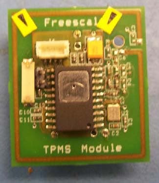
Click to zoom
Application Details
- Equipment Class
- DSC - Part 15 Security/Remote Control Transmitter
- Date of Grant
- Oct 24, 2007
- Application Purpose
- Original Equipment
- Date of Application
- Oct 23, 2007
- Equipment Note
- WIRELESS ISM BAND TRANSMITTER
- Frequency Range
- 434.00000000 - 434.00000000
- Company
- Axiom Manufacturing Inc
- Country
- United States
Documents & Files
Document Text
Text extracted from the exhibit documents filed with the FCC. Open a document above to read the original.
Users Manual
DOC-0422-010 Rev B.08/31/07 ٛ Axiom Manufacturing • 2813 Industrial Lane • Garland, TX 75041 Email: [email protected] Web: http://www.axman.com ٛ REIMS Module Application Module for the Freescale MXYP8300 Hardware User Guide Reference Documentation: 1) Freescale example REIMS application software and documentation for MXYP8300 specific application notes. 2) Freescale MXYP8300 device reference manuals for detailed device operation and electrical specifications. Table of Contents Cautionary Notes: ........................................................................................................................... 2 Terminology.................................................................................................................................... 3 Module Features ............................................................................................................................. 3 REIMS Module Block Diagram .....................................................................................................4 Operational Description .................................................................................................................. 4 PWR_EN Option ............................................................................................................................ 5 J1 Connector – Development Access Port...................................................................................... 5 Battery............................................................................................................................................. 5 REIMS Module Hardware User Guide 2 Cautionary Notes: 1) Electrostatic Discharge (ESD) prevention measures should be applied whenever handling this product. ESD damage is not a warranty repair item. 2) Axiom Manufacturing reserves the right to make changes without further notice to any products to improve reliability, function or design. Axiom Manufacturing does not assume any liability arising out of the application or use of any product or circuit described herein; neither does it convey any license under patent rights or the rights of others. 3) EMC Information on the REIMS Module: a) This device complies with Part 15 of the FCC Rules. Operation is subject to the following two conditions: 1) This device may not cause harmful interference, and 2) This device must accept any interference received, including interference that may cause undesired operation. TX FCC ID# TFY042201 (315Mhz version) TX FCC ID# TFY042202 (434Mhz version) b) Changes or modifications to this unit not expressly approved by Axiom Manufacturing, could void the user’s authority to operate this equipment under FCC or other regulatory agency rules. c) This product is designed and intended for use as an application development or evaluation platform in an educational or professional laboratory. This product is not intended for application or installation in end user equipment or systems. d) In a domestic environment this product may cause radio interference in which case the user may be required to take adequate prevention measures. e) RF Exposure – This device exceeds the FCC requirements for RF exposure when the antenna used for this transmitter has a separation distance of at least 20cm from all persons and must not be co-located or operating in conjunction with any other antenna or transmitter. REIMS Module Hardware User Guide 3 Terminology This module applies option selection jumpers. Terminology for application of the option jumpers is as follows: Jumper on, in, or installed = jumper is a plastic wired shunt that fits across 2 pins and the shunt is installed so that the 2 pins are connected with the shunt. Jumper off, out, or idle = jumper or shunt is installed so that only 1 pin holds the shunt, no 2 pins are connected, or jumper is removed. It is recommended that the jumpers be placed idle by installing on 1 pin so they will not be lost. Signal names in this document that are followed by an asterisk (*) denote an active-low signal. Module Features The REIMS Module is a demonstration, evaluation, or application development platform for the Freescale MXYP8300 device. Module operation is controlled by dedicated firmware contained in the MXYP8300 memory. The MXYP8300 provides air pressure, temperature, and accelerometer measurements with a 315MHz or 434MHz RF transmitter and 125KHz LF receiver. Typical application would be to monitor and transmit tire pressure and status in a vehicle Tire Pressure Monitoring System (TPMS). The device is well suited for many industrial monitoring or safety applications. The Module applies an embedded RF antenna and does not provide external connections for measurements, RF, or LF signals. Access to the MXYP8300 device is provided by an adapter cable and the J1 development port connector. A HCS08 BDM cable with 2.5 to 3.3V I/O may be applied, see the J1 Development Port section for more details. The module is a component of the Freescale REIMS TPMS demonstration kit. See the kit documentation for a system overview and demonstration operation details. REIMS Module Hardware User Guide 4 REIMS Module Block Diagram Operational Description The REIMS Module is a basic demonstration platform for the MXYP8300 device. Two module configurations are available, 315MHz and 434MHz transmit frequency versions. All other features and operational characteristics are the same for the modules. The MXYP8300 device integrates pressure, temperature, and accelerometer sensors with a HCS08 MCU, wireless ISM band RF transmitter, and wireless LF band 125KHz receiver. Typical application provides for measurement data to be transmitted to a system host. The transmissions are sent at a slightly random time interval greater than 10 seconds and/or may be keyed by reception of a 125KHz LF reception. Either method will meet Agency approval requirements for transmitter certification. Module power is derived from the on-board 3V battery. The MXYP…
Text truncated - open the document above for the full version.
Block Diagram
REIMS Module Block Diagram AXM-0422-02 434Mhz version MXYP8300 Device 3V Battery Integrated PCB RF antenna for 434Mhz transmitter 125KHz receiver coil J1 Development Port PWR_EN option jumper 22.0586MHz Oscillato r
Cover Letter(s)
Axiom Manufacturing ID: TFY042201 and TFY042202 Oct. 11, 2007 Modular Approval Disclaimer: Modular approval of the AXM0422-01 and AXM0422-02 REIMS TPMS modules is not required. The modules are Evaluation Boards for the integrated sensor device - the MPXY8300. Purpose of the modules is to evaluate the MPXY8300 sensor features and provide a small size module type reference design for review by TPMS system developers. The FCC registration of the intentional transmitter portion is to allow evaluation and demonstration of the sensor transmitter section. The module is intended to be a marketing demonstration platform for the MPXY8300 devices, not for end equipment application. Application as end equipment disclaimer: End equipment application will require a TPMS system sensor module to be mounted in a vehicle tire wheel assembly. Mechanical constraints and operating environment would prevent the submitted reference design from actually being applied as a system device in this manner. End equipment manufacturers will be required to adjust the design for application and certify the new design with the FCC and other compliance agencies. Intended Application Purpose: The modules will be sold in an evaluation kit for the MPXY8300 device. The evaluation kit will provide 2 modules and a compatible RF receiver device that connects to a host Personal computer. The demonstration application will allow the modules to be subjected to air pressure and other environment changes in a laboratory and then wirelessly communicate the sensor readings to the host PC for evaluation results. The evaluation method is intended to also provide an operational example of TPMS system application for the end equipment manufacturers. Roger Forrester Engineering Manager Axiom Manufacturing 2813 Industrial lane Garland, TX 75041
Operational Description
REIMS AXM0422 Operational Description09/24/07 Operational Description The REIMS Module is a basic demonstration platform for the MXYP8300 device. Two module configurations are available, 315MHz and 434MHz transmit frequency versions. All other features and operational characteristics are the same for the modules. The MXYP8300 device integrates air pressure, temperature, and X/Y/Z accelerometer sensors with a HCS08 MCU, wireless ISM band RF transmitter, and wireless LF band 125KHz receiver into a single device package. Typical application provides for the MXPY8300 to be mounted inside a tire wheel to provide measurement data to a Tire Pressure Monitoring System (TPMS) host for safety reporting to the vehicle operator. Module power is derived from the on-board 3V Lithium Coin cell battery. The MXYP8300 monitors the battery and will not operate or allow transmission if the voltage is too low. Option JP1 (PWR_EN) allows the module to be powered on or off. JP1 should be opened to save battery during storage of the evaluation modules. The battery may be replaced with another CR-2325 type 3.0V battery. Transmitter operation applies a fixed power setting with a +/-35KHz FSK modulation from the center carrier frequency of 315 or 434Mhz. Carrier frequency is derived from the reference crystal oscillator and a digital phase locked loop multiplier and divider. Transmitted data packets are sent at 9600 baud and typically contain 16 bytes of data (16ms transmit duration). Default application provides for a slightly random transmission time interval greater than 10 seconds and/or a select key 125KHz LF data reception. All configuration and control operations are performed by the HCS08 microcontroller and application firmware. Sensor data is collected as analog to digital measurement readings. To support long battery life the transmitter and external reference oscillator are powered off at all times until a message is to be sent. A very low power internal precision R/C clock is provided to allow the controller and LF125KHz receiver to operate without the external oscillator running. This clock also provides the random 10 second wake-up interval when timed transmissions are applied. The 315 or 434 MHz transmit antenna is an integral PCB copper trace. No adjustments or options are available. The LF125Khz reception antenna is a mounted transponder coil, L5.
Parts List/Tune Up Info
DOC-0422-020 REIMS TPMS Modules 315 and 434MHz 8/27/2007 QTY REF DES V ALUE Detail SUPPLIE R PART NUMBER 1 C1 10pF Capacitor, 10pF 5% COG, 0402 SMT TDK C1005C0G1H100DT 1 C2 0.01uF Capacitor, .01uF 10% X7R, 0402 SMT TDK C1005X7R1E103KT 1 C3 - 315M 68 pF Capacitor, 68pF 5% COG, 0402 SMT TDK C1005C0G1H680JT 1 C3 - 434M 47pF Capacitor, 47pF 5% COG, 0402 SMT TDK C1005C0G1H470JT 1C6 O OHM RESISTOR Resistor, 0 Ohm, 0402 SMT Vishay CRCW04020.0ZOED 2 C8, C10 100pF Capacitor, 100pF 5% COG, 0402 SMT TDK C1005C0G1H101JT 2 C9, C11 .1uF Capacitor, .1uF 10% X7R, 0402 SMT TDK C1005X7R1E103KT 1 C12 220pF Capacitor, 220pF 5% COG, 0402 SMT TDK C1005C0G1H221JT 1 C14 68 uF Capacitor, 100uF +80/-20% Y5V, 1210 SMT Murata GRM32EF50J107ZE20L 1 J4 JST 4 PINS Connector, 1mm x 4, SMT - Wire JST BM04B-SRSS-TB(LF)(SN) 1 L1 - 315M 56 nH Inductor, 56nH 5%, 0402 SMT TDK MLG1005S56NJT 1 L1 - 434M 18 nH Inductor, 18nH 5%, 0402 SMT TDK MLG1005S18NJT 1 L2 - 315M 180 nH Inductor, 180nH 5%, 0402 SMT TDK MLG1005S180NJT 1 L2 - 434M 56 nH Inductor, 56nH 5%, 0402 SMT TDK MLG1005S56NJT 1L3 O OHM RESISTOR Res. 0 OHM, 0402 SMT Vishay CRCW04020.0ZOED 0 L4 PCB LOOP ANTENNA Reference for PCB trace antenna only - - 1 L5 7.2 mH, SMT Inductor, 7.2mH, PREMO TP0702-0720J 1 U1 MXPY8300 IC, Sensor and transmitter, SOICW20 Freescale MXPY8300 1 U2 - 315M 16.0132Mhz xtal Crystal, 16.0132MHz, 3.5 x 2.5mm, SMT NDK NX3225SA-16.0132MHz 1 U2 - 434M 22.0586Mhz xtal Crystal, 22.0586MHz, 3.5 x 2.5mm, SMT NDK NX3225SA-22.0586MHz 0 C4, C5, C7, C16 NOT INSTALLED - - 0 R1 NOT INSTALLED - - 1 PCB PCB - AXM0422 Rev A. Axiom AXM-0402A 1
Parts List/Tune Up Info
DOC-0422-02-020 REIMS TPMS Module 434Mhz 8/31/2007 QTY REF DES V ALUE Detail SUPPLIE R PART NUMBER 1 C1 10pF Capacitor, 10pF 5% COG, 0402 SMT TDK C1005C0G1H100DT 1 C2 0.01uF Capacitor, .01uF 10% X7R, 0402 SMT TDK C1005X7R1E103KT 1 C3 47pF Capacitor, 47pF 5% COG, 0402 SMT TDK C1005C0G1H470JT 1C6 O OHM RESISTOR Resistor, 0 Ohm, 0402 SMT Vishay CRCW04020.0ZOED 2 C8, C10 100pF Capacitor, 100pF 5% COG, 0402 SMT TDK C1005C0G1H101JT 2 C9, C11 .1uF Capacitor, .1uF 10% X7R, 0402 SMT TDK C1005X7R1E103KT 1 C12 220pF Capacitor, 220pF 5% COG, 0402 SMT TDK C1005C0G1H221JT 1 C14 100 uF Capacitor, 100uF +80/-20% Y5V, 1210 SMT Murata GRM32EF50J107ZE20L 1 J4 4 PINS Connector, 2mm x 4, SMT JST BM04B-SRSS-TB(LF)(SN) 1 L1 18 nH Inductor, 18nH 5%, 0402 SMT TDK MLG1005S18NJT 1 L2 56 nH Inductor, 56nH 5%, 0402 SMT TDK MLG1005S56NJT 1L3 O OHM RESISTOR Res. 0 OHM, 0402 SMT Vishay CRCW04020.0ZOED 0 L4 PCB LOOP ANTENNA Reference for PCB trace antenna only - - 1 L5 7.2 mH, SMT Inductor, 7.2mH, PREMO TP0702-0720J 1 U1 MPXY8300 IC, Sensor and transmitter, SOICW20 Freescale MPXY8300 1 U2 22.0586Mhz xtal Crystal, 22.0586MHz, 3.5 x 2.5mm, SMT NDK NX3225SA-22.0586MHz 0 C4, C5, C7, C16 NOT INSTALLED - - 0 R1 NOT INSTALLED - - 1 PCB PCB - AXM0422 Rev A. Axiom AXM-0422A 1
Schematics
55 44 33 22 11 D D C C B B A A PTA1RPTA0R BKGD VDD RESET PTA0RPTA1R VDDVDDVDD RESETVDDBKGD TO LOOP ANT TO LOOP ANT TitleSize Document Number Rev Date: Sheet of DOC-0422-02-030 A REIMS TPMS MODULE 434 A 11 Friday, August 24, 2007 TitleSize Document Number Rev Date: Sheet of DOC-0422-02-030 A REIMS TPMS MODULE 434 A 11 Friday, August 24, 2007 TitleSize Document Number Rev Date: Sheet of DOC-0422-02-030 A REIMS TPMS MODULE 434 A 11 Friday, August 24, 2007 MXPY8300 U2 R1 DNI R1 DNI C4DNIC4DNI J8 TP3 J8 TP3 1 C9 100nF C9 100nF C10 100pF C10 100pF J5Valve Ant DNIJ5Valve Ant DNI 1 C5DNIC5DNI PCB TRACE L4 PCB TRACE L4 12 U1 REIMS U1 REIMS N/C1 20 AVDD 10 PTA3 12 BKGD 18 RESET 11 AVSS 9 PTA6 2 X1 3 PTA5 1 N/C2 19 VCAP 8 VSS 17 VRF 7 PTA2 13 RF 6 PTA1 14 RVss 5 PTA0 15 X0 4 VDD 16 22.0586MHz NX3225GA 22.0586MHz NX3225GA NC2 2 IN2 3 NC1 4 IN1 1 C11 100nF C11 100nF C7DNIC7DNI J2 CON1 J2 CON1 1 L5 7.2mH L5 7.2mH 12 C6 0 OHM C6 0 OHM C16DNIC16DNI C2 10nF C2 10nF L3 0 OHM L3 0 OHM J1 CON1 J1 CON1 1 L2 56nH L2 56nH 1 2 L1 18nH L1 18nH 12 J7 TP1 J7 TP1 1 C12220pFC12220pF 12 J3 CON1 J3 CON1 1 C3 47pF C3 47pF C8100pFC8100pF J9 TP4 J9 TP4 1 C14 68uF C14 68uF J6 CON1 J6 CON1 1 J4 CON4 J4 CON4 1234 C110pFC110pF
Test Report
Nemko Test Report: 7465RUS1 Applicant: Axiom Manufacturing 2841 Industrial Lane Garland, TX 75041 Equipment Under Test: AXM042202 (434MHZ) (E.U.T.) In Accordance With: FCC Part 15, Subpart C For Low Power Transmitters Operating Periodically In The Band 40.66 - 40.77 MHz And Above 70 MHz Tested By: Nemko USA, Inc. 802 N. Kealy Lewisville, TX 75057-3136 TESTED BY: DATE: 13 August 2007 David Light, Senior Wireless Engineer APPROVED BY: DATE: 3 October 2007 Mike Cantwell, Frontline Manager Total Number of Pages: 20 Nemko USA, Inc. FCC PART 15, SUBPART C PERIODICALLY OPERATED LOW POWER TRANSMITTERS EQUIPMENT: AXM042202 (434MHZ) PROJECT NO.: 7465RUS1 Page 2 of 20 TABLE OF CONTENTS SECTION 1. SUMMARY OF TEST RESULTS 3 SECTION 2. EQUIPMENT UNDER TEST (E.U.T.) 5 SECTION 3. TRANSMISSION REQUIREMENTS 7 SECTION 4. RADIATED EMISSIONS 9 SECTION 5. OCCUPIED BANDWIDTH 12 SECTION 6. PERIODIC ALTERNATE FIELD STRENGTH REQUIREMENTS 14 SECTION 7. BLOCK DIAGRAMS 16 SECTION 8. TEST EQUIPMENT LIST 18 ANNEX A - RESTRICTED BANDS 19 Nemko USA, Inc. FCC PART 15, SUBPART C PERIODICALLY OPERATED LOW POWER TRANSMITTERS EQUIPMENT: AXM042202 (434MHZ) PROJECT NO.: 7465RUS1 Page 3 of 20 Section 1. Summary of Test Results Manufacturer: Axiom Manufacturing Model No.: AXM042202 (434MHZ) Serial No: None General: All measurements are traceable to national standards. These tests were conducted on a sample of the equipment for the purpose of demonstrating compliance with Part 15, Subpart C, Paragraph 15.231. All tests were conducted using measurement procedure ANSI C63.4-2003. Radiated emissions are made on an open area test site. A description of the test facility is on file with the FCC. New Submission Production Unit Class II Permissive Change Pre-Production Unit THIS TEST REPORT RELATES ONLY TO THE ITEM(S) TESTED. THE FOLLOWING DEVIATIONS FROM, ADDITIONS TO, OR EXCLUSIONS FROM THE TEST SPECIFICATIONS HAVE BEEN MADE. See “ Summary of Test Data”. Nemko USA Inc. authorizes the above named company to reproduce this report provided it is reproduced in its entirety and for use by the company’s employees only. Any use which a third party makes of this report, or any reliance on or decisions to be made based on it, are the responsibility of such third parties. Nemko USA Inc. accepts no responsibility for damages, if any, suffered by any third party as a result of decisions made or actions based on this report. This report applies only to the items tested. Nemko USA, Inc. FCC PART 15, SUBPART C PERIODICALLY OPERATED LOW POWER TRANSMITTERS EQUIPMENT: AXM042202 (434MHZ) PROJECT NO.: 7465RUS1 Page 4 of 20 Summary Of Test Data Name of Test Paragraph No. Results Transmission Requirements 15.231(a) Complies Radiated Emissions 15.231(b) Complies Occupied Bandwidth 15.231(c) Complies Frequency Tolerance 15.231(d) NA Alternate Field Strength Requirements 15.231(e) Complies Powerline Conducted Emissions 15.207 NA Footnotes: The device operates above 40.70 MHz The device is battery powered. Nemko USA, Inc. FCC PART 15, SUBPART C PERIODICALLY OPERATED LOW POWER TRANSMITTERS EQUIPMENT: AXM042202 (434MHZ) PROJECT NO.: 7465RUS1 Page 5 of 20 Section 2. Equipment Under Test (E.U.T.) General Equipment Information Frequency Range: 434 MHz fixed Operating Frequency(ies) of Sample: 434 MHz Type of Emission: FSK Supply Power Requirement: 3 Vdc Duty Cycle Correction Factor: None Nemko USA, Inc. FCC PART 15, SUBPART C PERIODICALLY OPERATED LOW POWER TRANSMITTERS EQUIPMENT: AXM042202 (434MHZ) PROJECT NO.: 7465RUS1 Page 6 of 20 Description of E.U.T. Tire Pressure sensor and transmitter with integrated antenna. Module designed for small size and battery power, to fit in car wheel assembly. Application is is for evaluation of automotive safety system. Nemko USA, Inc. FCC PART 15, SUBPART C PERIODICALLY OPERATED LOW POWER TRANSMITTERS EQUIPMENT: AXM042202 (434MHZ) PROJECT NO.: 7465RUS1 Page 7 of 20 Section 3. Transmission Requirements NAME OF TEST: Transmission Requirements PARA. NO.: 15.231(a) TESTED BY: David Light DATE: 7/31/07 Minimum Standard: 15.231(a) Continuous transmissions such as voice, video or data transmissions are not permitted. 15.231(a)(1) A manually operated transmitter shall employ a switch that will automatically deactivate the transmitter within not more than 5 seconds after being released. 15.231(a)(2) A transmitter activated automatically shall cease transmission within 5 seconds of activation. 15.231(a)(3) Periodic transmissions at regular pre- determined intervals are not permitted. However polling or supervisory transmissions to determine system integrity of transmitters used in security or safety applications are allowed if the periodic rate of transmission does not exceed one transmission of not more than one second duration per hour for each transmitter. 15.231(a)(4) Intentional radiators which are employed for radio control purposes during emergencies involving fire, security, and safety of life, when activated to signal an alarm, may operate during the pendency of the alarm. Test Results: Complies. Test Data: Compliance was determined by verification of technical specifications and a functional test on the equipment. Refer to plots on page 8 Nemko USA, Inc. FCC PART 15, SUBPART C PERIODICALLY OPERATED LOW POWER TRANSMITTERS EQUIPMENT: AXM042202 (434MHZ) PROJECT NO.: 7465RUS1 Page 8 of 20 Rationale for Compliance with Transmission Requirements Manual activation 15.231(a)(1) 15.231(a)(2) : Automatic activation TX deactivation time: Regular, predetermined transmissions 15.231(a)(3) : Polling or supervisory transmissions TX rate and duration: Alarm device operating during the pendancy of alarm condition 15.231(a)(4) : Non-alarm device Transmitter release time less than one second. Nemko USA, Inc. FCC PART 15, SUBPART C PERIODICALLY OPERATED LOW POWER TRANSMITTERS EQUIPMENT: AXM042202 (434MHZ) PROJECT NO.: 7465RUS1 Page 9 of 20 Section 4. Radiated Emissions NAME OF TEST: Radiated Emissions PARA. NO.: 15.231(b) TESTED BY: David Light DAT…
Text truncated - open the document above for the full version.
Contact Information
Applicant
Roger Forrester(Engineering Manager)
Test Firm
Nemko USA, Inc.Tom Tidwell
Technical Specifications
| # | Rule Parts | Frequency Range | Power Output |
|---|---|---|---|
| 1 | 15.231(e) | 434 MHz - 434 MHz | - |
Other Applications from Axiom Manufacturing Inc
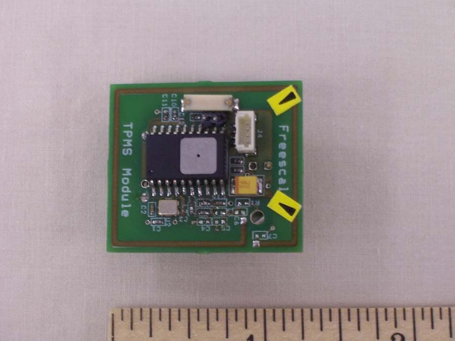
TFY042201
Oct 18, 2007WIRELESS ISM BAND TRANSMITTER
Equipment Class
DSC - Part 15 Security/Remote Control Transmitter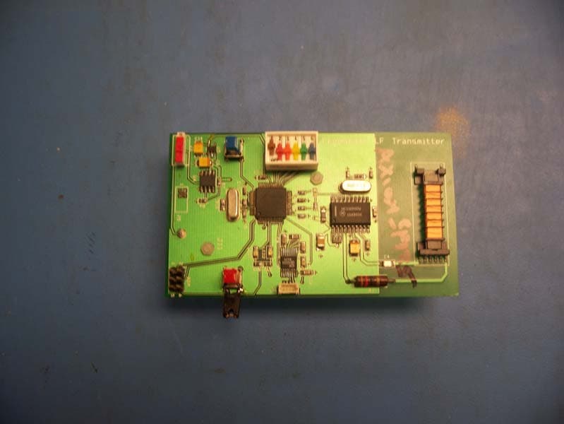
TFY0423
Oct 16, 2007LF125KHZ TPMS TRANSMITTER
Equipment Class
DCD - Part 15 Low Power Transmitter Below 1705 kHz