TGERJP-100MREMOTE JACK PACK
KIMIN Electronics Co., Ltd.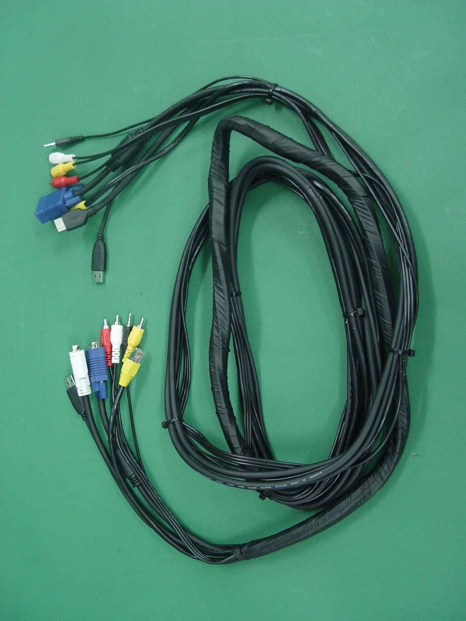
Click to zoom
Application Details
- Equipment Class
- JBP - Part 15 Class B Computing Device Peripheral
- Date of Grant
- Jul 17, 2005
- Application Purpose
- Original Equipment
- Date of Application
- Jul 17, 2005
- Equipment Note
- REMOTE JACK PACK
- Company
- KIMIN Electronics Co., Ltd.
- Country
- South Korea
Documents & Files
Document Text
Text extracted from the exhibit documents filed with the FCC. Open a document above to read the original.
Users Manual
EUT Type: RJP-100M FCC ID: TGERJP-100M Test Report No.: GETEC-E3-05-052 FCC Class B Certification APPENDIX H : USER’S MANUAL RJP-100M Remote Jack Pack Installation & Setup Guide Warranty © Copyright 2005, LGElectronics U.S.A., Inc. 2 For Customer Support/Service, please call: 1-888-865-3026 www.lgcommercial.com 206-4010 The exclamation point within an equilateral triangle is intended to alert the user to the presence of important operating and maintenance (servicing) instructions in the literature accompanying the appliance. CAUTION: TO REDUCE THE RISK OF ELECTRIC SHOCK - - USE ONLY INDOORS ATTENTION: RISQUE DE CHOCS ÉLECTRIQUE - - POUR INSTALLATION À L¡ ̄INTÉRIEUR SEULEMENT WARNING: TO PREVENT FIRE OR SHOCK HAZARDS, DO NOT EXPOSE THIS PRODUCT TO RAIN OR MOISTURE. Apparatus shall not be exposed to dripping or splashing and no objects filled with liquids, such as vases, shall be placed on the apparatus. L’appareil ne doit pas être exposé à des égouttements d’eau ou des éclaboussures et de plus qu’aucun objet rempli de liquide tel que des vases ne doit être placé sur l’appareil. REGULATORY INFORMATION: This equipment has been tested and found to comply with the limits for a Class B digital device, pur- suant to Part 15 of the FCC Rules. These limits are designed to provide reasonable protection against harmful interference when the equipment is operated in a residential installation. This equipment gen- erates, uses and can radiate radio frequency energy and, if not installed and used in accordance with the instruction manual, may cause harmful interference to radio communications. However, there is no guarantee that interference will not occur in a particular installation. If this equipment does cause harmful interference to radio or television reception, which can be determined by turning the equip- ment off and on, the user is encouraged to try to correct the interference by one or more of the fol- lowing measures: • Reorient or relocate the receiving antenna. • Increase the separation between the equipment and receiver. • Connect the equipment into an outlet on a circuit different from that to which the receiver is connected. • Consult the dealer or an experienced radio/TV technician for help. CAUTION: Do not attempt to modify this product in any way (except as noted herein) without written authoriza- tion from LG Electronics U.S.A., Inc. Unauthorized modification could void the user’s authority to operate this product. COMPLIANCE: The responsible party for this product’s compliance is: LG Electronics U.S.A., Inc., 2000 Millbrook Drive Lincolnshire, IL 60069, USA • Phone: 1-847-941-8000. ©Copyright 2005, LG Electronics U.S.A., Inc. Note: Design and specifications are subject to change without prior notice. Marketed and Distributed in the United States by LG Electronics U.S.A., Inc. 2000 Millbrook Drive, Lincolnshire, IL 60069 PHONE NETWORK AUDIO INAUDIO INVIDEO IN S-VIDEO IN PC VIDEO INDIGITAL VIDEO INUSB IN L R 10 AMP MAXIMUM CURRENT P R E S T O S R E S E T Overview The Remote Jack Pack (RJP) contains circuitry to determine the presence of a signal at each input jack. (Note: The initial implementation only monitors the right audio input of each audio source.) When a signal is detected, it’s priority is compared to the priori- ty of other sources which may be present. Control signals from the RJP to the display panel change state, if the new active source is of higher priority than the existing source, to direct the display panel to proper source. Video and audio are monitored and switched independently. Power is supplied to the RJP by the display panel via the control signal cable. 3 206-4010 206-4010 Introduction Conveniently installed right in the room where guests will stay, the LG Remote Jack Pack, multi-media interface is available to end users to connect audio, video and computer devices to hear and view on the in-room TV display panel. The RJP-100M can be set up to interface with the TV display panel to show the image and/or sound from a portable DVD/CD Player, Camcorder, MP-3 Player, Notebook computer, or portable Video Game Player. Or, devices with digital video outputs such as DVD players. A USB-2.0 connection is available for future applications. If the end user does not connect any devices, then the in-room TV display panel will remain on the source selected. When the end user connects a device, the interface switches the TV display panel to the new source. Satellite radio may be available at some locations. Users can charge laptops or cell phones while watching TV. The RJP-100M interface is designed to be able to process audio from one source, and video separately from a different source, if required. (A user can do work on a laptop PC and hear music from an MP-3 player.) However, only one audio and one video source can be heard/seen at the same time. The user simply plugs the device’s power cord into one of the four conve- nience AC power outlets provided on the RJP-100M. Turns the device on and the RJP-100M switches to the newly-connected audio and/or video source. No end user menus are involved, connections are made directly to the interface. The RJP-100M continually monitors the signal of the source inputs. When a signal is detected, (a device is plugged into one of the source inputs) the interface sends a message to the TV display panel which then switches to the newly-connected source. The interface sends the audio and video so that it can be heard and seen on the TV display panel. 12-Volt DC power is supplied from the TV display panel to operate the interface via the control cable. Overview (Contd.) CLEANING CAUTION: Since the end user jackpack is exposed, use extreme caution when cleaning. Do not use liquid cleaners on the connections panel. Do not allow liquids to be spilled, sprayed onto or otherwise come into contact with the connections panel on both the end user side and the installer side. Clean with a slightly damp cloth. 10 AMPS MAXIMUM TO ALL FOUR AC OUTL…
Text truncated - open the document above for the full version.
Block Diagram
EUT Type: RJP-100M FCC ID: TGERJP-100M Test Report No.: GETEC-E3-05-052 FCC Class B Certification APPENDIX D : BLOCK DIAGRAM TV RE M O T E JACK PACK (RJP- 1 0 0 M ) B l ock D i agram AC IN 120V~ , 60H Z MAX 10A 10A CIRCUIT B R EA KE R AC OUT,NE MA5-15R RE CEPTACLE RELOCAT ABLE POWER T A PS PART PRE S S TO RES E T AC OUT,NE MA5-15R RE CEPTACLE AC OUT,NE MA5-15R RE CEPTACLE AC OUT,NE MA5-15R RE CEPTACLE RJ1 1 IN RJ4 5 IN MP3 AUDI O R , L IN COMP V I DE O I N S VIDE O IN RGB IN HDMI IN USB IN A N ALOG PAR T RJ1 1 OUT RJ4 5 OUT USB OUT SAT RADI O A UDI O R , L OU T MPU DIGIT A L PA RT CONTR O L OUT +5 V RE GU L A TO R F EED T H RO UGH F EED T H RO UGH V I D E O OUT RGB OUT HDMI OUT F EED T H RO UGH SE LECTOR +5V PO RT A B LE ELECTRONIC UN IT WAL L OUTLET JA C K PA N E L WAL L OUTLET JA C K PA N E L PO RT A B LE ELECTRIC UN IT REMOT E JACK PACK PART +12 V
External Photos
EUT Type: RJP-100M FCC ID: TGERJP-100M Test Report No.: GETEC-E3-05-052 FCC Class B Certification APPENDIX F : EXTERNAL PHOTOGRAPHS EUT Type: RJP-100M FCC ID: TGERJP-100M Test Report No.: GETEC-E3-05-052 FCC Class B Certification EUT Type: RJP-100M FCC ID: TGERJP-100M Test Report No.: GETEC-E3-05-052 FCC Class B Certification EUT Type: RJP-100M FCC ID: TGERJP-100M Test Report No.: GETEC-E3-05-052 FCC Class B Certification EUT Type: RJP-100M FCC ID: TGERJP-100M Test Report No.: GETEC-E3-05-052 FCC Class B Certification EUT Type: RJP-100M FCC ID: TGERJP-100M Test Report No.: GETEC-E3-05-052 FCC Class B Certification EUT Type: RJP-100M FCC ID: TGERJP-100M Test Report No.: GETEC-E3-05-052 FCC Class B Certification EUT Type: RJP-100M FCC ID: TGERJP-100M Test Report No.: GETEC-E3-05-052 FCC Class B Certification EUT Type: RJP-100M FCC ID: TGERJP-100M Test Report No.: GETEC-E3-05-052 FCC Class B Certification EUT Type: RJP-100M FCC ID: TGERJP-100M Test Report No.: GETEC-E3-05-052 FCC Class B Certification EUT Type: RJP-100M FCC ID: TGERJP-100M Test Report No.: GETEC-E3-05-052 FCC Class B Certification EUT Type: RJP-100M FCC ID: TGERJP-100M Test Report No.: GETEC-E3-05-052 FCC Class B Certification EUT Type: RJP-100M FCC ID: TGERJP-100M Test Report No.: GETEC-E3-05-052 FCC Class B Certification EUT Type: RJP-100M FCC ID: TGERJP-100M Test Report No.: GETEC-E3-05-052 FCC Class B Certification
ID Label/Location Info
EUT Type: RJP-100M FCC ID: TGERJP-100M Test Report No.: GETEC-E3-05-052 FCC Class B Certification APPENDIX C : ID SAMPLE LABEL & LOCATION EUT Type: RJP-100M FCC ID: TGERJP-100M Test Report No.: GETEC-E3-05-052 FCC Class B Certification LABELLING REQUIREMENTS The label shown shall be permanently affixed at a conspicuous location on the device and be readily visible to the user at the time of purchase. ID Label ID Label Location of EUT I.D Label
Internal Photos
EUT Type: RJP-100M FCC ID: TGERJP-100M Test Report No.: GETEC-E3-05-052 FCC Class B Certification APPENDIX G : INTERNAL PHOTOGRAPHS EUT Type: RJP-100M FCC ID: TGERJP-100M Test Report No.: GETEC-E3-05-052 FCC Class B Certification EUT Type: RJP-100M FCC ID: TGERJP-100M Test Report No.: GETEC-E3-05-052 FCC Class B Certification EUT Type: RJP-100M FCC ID: TGERJP-100M Test Report No.: GETEC-E3-05-052 FCC Class B Certification
Test Report
EUT Type: RJP-100M FCC ID: TGERJP-100M Page 2 of 18 Test Report No.: GETEC-E3-05-052 FCC Class B Certification CONTENTS 1. SCOPE...........................................................................................................................................................................3 2. INTRODUCTION ........................................................................................................................................................4 3. TEST CONDITIONS & EUT INFORMATION........................................................................................................5 3.1 DESCRIPTION OF EUT..............................................................................................................................................5 3.2 SUPPORT EQUIPMENT USED.....................................................................................................................................6 4. DESCRIPTION OF TESTS.........................................................................................................................................7 4.1 CONDUCTED EMISSION............................................................................................................................................7 4.2 RADIATED EMISSION................................................................................................................................................8 5. CONDUCTED EMISSION..........................................................................................................................................9 5.1 OPERATING ENVIRONMENT.....................................................................................................................................9 5.2 TEST SET-UP..............................................................................................................................................................9 5.3 MEASUREMENT UNCERTAINTY................................................................................................................................9 5.4 LIMIT......................................................................................................................................................................10 5.5 TEST EQUIPMENT USED..........................................................................................................................................10 5.6 TEST DATA FOR POWER LINE CONDUCTED EMISSION............................................................................................ 11 6. RADIATED EMISSION ............................................................................................................................................13 6.1 OPERATING ENVIRONMENT...................................................................................................................................13 6.2 TEST SET-UP............................................................................................................................................................13 6.3 MEASUREMENT UNCERTAINTY..............................................................................................................................13 6.4 LIMIT......................................................................................................................................................................14 6.5 TEST EQUIPMENT USED..........................................................................................................................................14 6.6 TEST DATA FOR RADIATED EMISSION.....................................................................................................................15 7. SAMPLE CALCULATIONS.....................................................................................................................................17 7.1 EXAMPLE 1 : ...........................................................................................................................................................17 7.2 EXAMPLE 2 : ...........................................................................................................................................................17 8. RECOMMENDATION & CONCLUSION..............................................................................................................18 APPENDIX A – ATTESTATION STATEMENT APPENDIX B – PLOTS OF CONDUCTED EMISSIONS APPENDIX C – ID SAMPLE LABEL & LOCATION APPENDIX D – BLOCK DIAGRAM APPENDIX E – TEST SET-UP PHOTOGRAPHS APPENDIX F – EXTERNAL PHOTOGRAPHS APPENDIX G –INTERNAL PHOTOGRAPHS APPENDIX H – USER’S MANUAL EUT Type: RJP-100M FCC ID: TGERJP-100M Page 3 of 18 Test Report No.: GETEC-E3-05-052 FCC Class B Certification 1. Scope Measurement and determination of electromagnetic emissions (EME) of radio frequency devices including intentional and / or unintentional radiators for compliance with technical rules and regulations of the Federal Communications Commission . z FCC ID TGERJP-100M z EUT Type Remote jack pack z Model No. RJP-100M z Tra de Na me LG, ZENITH, KIMIN z Rule Part(s) FCC Part 15 Subpart B z Test Procedure(s) ANSI C63.4 (2003) z Dates of Test July 3 ~ 6, 2005 z Place of Test Gumi College EMC Center z Test Report No. GETEC-E3-05-052 Responsible Party: Kimin Electronic Co., Ltd. Contact Person: Mr. Se-bong Jang, General Manager Manufacturer: 293-4 , Gongdan-dong, Gumi-city, Gyeongsangbuk-do, Korea Tel No.: +82-54-462-0100 EUT Type: RJP-100M FCC ID: TGERJP-100M Page 4 of 18 Test Report No.: GETEC-E3-05-052 FCC Class B Certification 2. Introduction The measurement procedure described in American National Standard for Methods of Measurement of Radio-Nose Emissions From Low-Voltage Electrical and Electronic Equipment in the Range of 9kHz to 40GHz (ASNI C63.4- 2003) was used in determining radiated and conducted emissions emanating from Kimin Electronic Co., Ltd. Remote jack pack(Model No.: RJP-100M) These measurement tests were cond…
Text truncated - open the document above for the full version.
Test Setup Photos
EUT Type: RJP-100M FCC ID: TGERJP-100M Test Report No.: GETEC-E3-05-052 FCC Class B Certification APPENDIX E : TEST SET UP PHOTOGRAPHS EUT Type: RJP-100M FCC ID: TGERJP-100M Test Report No.: GETEC-E3-05-052 FCC Class B Certification The Conducted Test Picture and Radiated Test Picture show the worst-case configuration and cable placement. Conducted Test Picture (Front) Conducted Test Picture (Rear) EUT Type: RJP-100M FCC ID: TGERJP-100M Test Report No.: GETEC-E3-05-052 FCC Class B Certification Radiated Test Picture (Front) Radiated Test Picture (Rear)
Contact Information
Applicant
Kyu-Hwan Kim(Genaral Manager)
Test Firm
Gumi University EMC CenterTae-Sig Park
Technical Specifications
| # | Rule Parts | Frequency Range | Power Output |
|---|---|---|---|
| 1 | 15B | - | - |
Other Applications from KIMIN Electronics Co., Ltd.
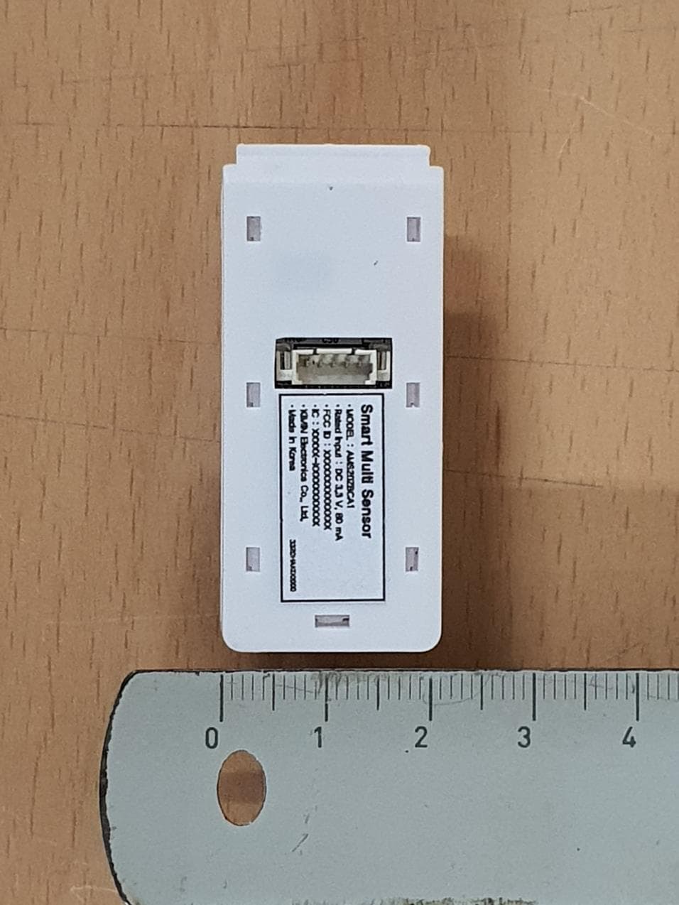
TGEACM20ZBEA1
Jan 08, 2024Integrated Multi Sensor Module
Equipment Class
DTS - Digital Transmission System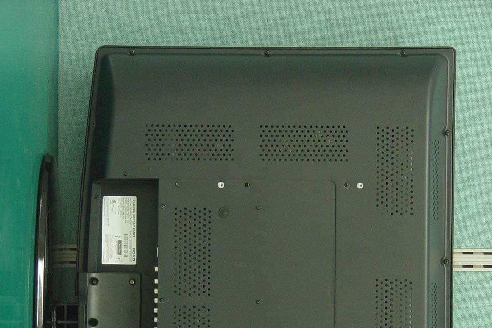
TGEPT32U44K
Mar 10, 2008PDP TV
Equipment Class
JBP - Part 15 Class B Computing Device Peripheral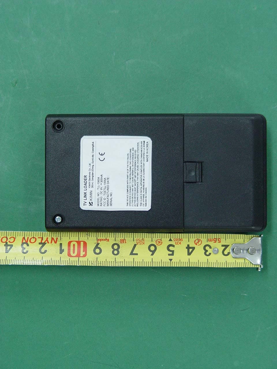
TGETLL-1000A
Oct 30, 2005TV LINK LOADER
Equipment Class
JBP - Part 15 Class B Computing Device Peripheral