TIC-RS06AURemote Control Starter System
Honda Access Corp.
Click to zoom
Application Details
- Equipment Class
- DSR - Part 15 Remote Control/Security Device Transceiver
- Date of Grant
- Aug 24, 2005
- Application Purpose
- Original Equipment
- Date of Application
- Aug 24, 2005
- Equipment Note
- Remote Control Starter System
- Frequency Range
- 429.17500000 - 429.17500000
- Company
- Honda Access Corp.
- Country
- Japan
Documents & Files
Document Text
Text extracted from the exhibit documents filed with the FCC. Open a document above to read the original.
Users Manual
© Honda Access Corp. 2005 1 Remote Control Car Starter SystemOwner’s Manual 2 © Honda Access Corp. 2005 Safety Messages• If instructions are preceded by a safety alert symbol and one of three signal words: DANGER , WARNING , or CAUTION . Three signal words mean: Other Symbols• If instructions are preceded by the following symbols, they will give helpful advice or information. DANGER WARNING CAUTION ADVICE INFORMATION Gives helpful information or instructions to be followed in using the product. • Gives advice to prevent damage to the product.• Gives advice to handle emergency situation. You WILL be KILLED or SERIOUSLY HURT if you don’t follow instructions.You CAN be KILLED or SERIOUSLY HURT if you don’t follow instructions.You CAN be HURT if you don’t follow instructions. © Honda Access Corp. 2005 3 Contents Introduction ............................................................................................................................... ........................................... 4 Precautions <For Safety> ....................................................................................................... ............................................ 5 Precautions <For Safety (Tr ansmitter)> ......................................................................................... .................................... 7 System Of Remote Control Car Star ter Sys tem .................................................................................... ............................ 9 Function Of Remote Control Car Starter System .................................................................................. .......................... 10 Before Leaving Your Car ........................................................................................................ ........................................... 12 Starting The Engine ..... ....................................................................................................... .............................................. 14 Stopping The Engine ............................................................................................................ ............................................. 16 To Stop The Engi ne A utomatically ............................................................................................... ..................................... 17 Checking Car Condition ......................................................................................................... ........................................... 18 Function Of Keyless Entry-Integ rated Key ....................................................................................... ................................ 20 Optional Item .................................................................................................................. ................................................... 23 Air Conditioner-Interlocking Function At Engine Start <Only the car with automatic climate control> .......................... 24 Function Of Standard Equipped Keyless Entry-integrated KeyDuring Warming Up With Remote Control Car Starter System ....................................................................... ............... 28 Transmitter Batter y Replacement ................................................................................................ ..................................... 29 Troubleshooting ............................................................................................................................... .................................. 31 Specifications ............................................................................................................................... ..................................... 35 4 © Honda Access Corp. 2005 Introduction Congratulations! Your selection of a Honda RemoteControl Starter System was a wise investment. Thissystem is the result of extensive research anddevelopment, and will provide you with many years ofreliable performance, protection, and convenience.The remote control starter system consists of atransmitter that allows you to start and stop the enginefrom outside the vehicle. You can also use thetransmitter to lock and unlock the doors, as well asactivate the horn in case of emergency.Some communities may have restrictions on the use ofremote starters. Before using your remote control startersystem, please check all local laws and regulations.To take full advantage of your Honda Remote ControlStarter System, please read this manual thoroughly. This device complies with part 15 of the FCC Rules.Operation is subject to the following two conditions:(1) This device may not cause harmful interference, and(2) this device must accept any interference received,including interference that may cause undesiredoperation.This device complies with RSS-210 of Industry andScience Canada. Operation is subject to the followingtwo conditions: (1) This device may not causeinterference, and (2) This device must accept anyinterference, including interference that may causeundesired operation of the device. Due to the expertise required to properly install theHonda Remote Control Starter System, we highlyrecommend that the installation be performed by yourHonda dealer. Proper wiring and componentplacement are essential for optimum systemperformance. © Honda Access Corp. 2005 5 5412071K WARNING Precautions <For Safety> • Starting your car in an enclosed area can cause toxic carbon monoxide build-up.Breathing this odorless gas can causeunconsciousness and even death.Do not use the remote starter to run your enginein a closed garage or other area with poorventilation. • Do not operate the remote control car starter systemto start the engine withoutremoving the body coverfrom the car. It can cause afire. 5412081K • Do not start the engine with this remote control carstarter system near theflammable material such asthe dead grass, paper, oil,grease, wood, etc.The heat from …
Text truncated - open the document above for the full version.
Cover Letter(s)
1 Helen Zhao Subject:FW: Honda Access Corp. , FCC ID: TIC-RS06AU, Assessment NO.: AN05T5089, Notice#1 Setup Photos(revised).pdf 05I3638-1 FCC 15.231 Report(r... Hi Helen, Pls see answer below. Question #1: The test report indicates that no cable no support equipment was ever used during the test, but the Setup photos show the device was connected with the cables (DC power source might be used). Please update the test report. <answer>report is revised. setup photos is also revised due page number changed. Quesiton #2: Parts List is submitted as one of technical documents, but it is not listed on confidentiality letter. Please confirm Parts list is OK for public inspection. <answer>client decided NOT to submit parts list to TCB. Thanks, Claire
ID Label/Location Info
PROPOSED FCC ID LABEL AND LOCATION Honda Access Corp. This device complies with Part 15 of the FCC Rules. Operation is subject to the following two conditions: (1) this device may not cause harmful interference, and (2) this device must accept any interference received, including interference that may cause undesired operation. FCC ID: TIC-RS06AU FCC ID LABEL
Test Report
FCC CFR47 PART 15 SUBPART C CERTIFICATION TEST REPORT FOR REMOTE CONTROL STARTER SYSTEM MODEL NUMBER: RS-06AU FCC ID: TIC-RS06AU REPORT NUMBER: 05I3638-1 ISSUE DATE: AUGUST 24, 2005 Prepared for HONDA ACCESS CORP. 4630 SHIMOTAKANEZAWA, HAGA-MACHI, HAGA-GUN, TOCHIGI, 321-3393, JAPAN Prepared by COMPLIANCE CERTIFICATION SERVICES 561F MONTEREY ROAD, MORGAN HILL, CA 95037, USA TEL: (408) 463-0885 FAX: (408) 463-0888 REPORT NO: 05I3638-1 DATE: AUGUST 24, 2005 EUT: REMOTE CONTROL STARTER SYSTEM FCC ID: TIC-RS06AU Page 2 of 29 COMPLIANCE CERTIFICATION SERVICES DOCUMENT NO: CCSUP4031A 561F MONTEREY ROAD, MORGAN HILL, CA 95037 USA TEL: (408) 463-0885 FAX: (408) 463-0888 This report shall not be reproduced except in full, without the written approval of CCS. Revision History Rev. Issue Date Revisions Revised By A 8/23/05 Initial Issue MH REPORT NO: 05I3638-1 DATE: AUGUST 24, 2005 EUT: REMOTE CONTROL STARTER SYSTEM FCC ID: TIC-RS06AU Page 3 of 29 COMPLIANCE CERTIFICATION SERVICES DOCUMENT NO: CCSUP4031A 561F MONTEREY ROAD, MORGAN HILL, CA 95037 USA TEL: (408) 463-0885 FAX: (408) 463-0888 This report shall not be reproduced except in full, without the written approval of CCS. TABLE OF CONTENTS 1. ATTESTATION OF TEST RESULTS ................................................................................................ 4 2. TEST METHODOLOGY..................................................................................................................... 5 3. FACILITIES AND ACCREDITATION .............................................................................................. 5 4. CALIBRATION AND UNCERTAINTY ............................................................................................ 5 4.1. MEASURING INSTRUMENT CALIBRATION ............................................................................. 5 4.2. MEASUREMENT UNCERTAINTY ............................................................................................... 5 5. EQUIPMENT UNDER TEST .............................................................................................................. 6 5.1. DESCRIPTION OF EUT ..............................................................................................................6 5.2. SOFTWARE AND FIRMWARE .................................................................................................... 6 5.3. WORST-CASE CONFIGURATION AND MODE......................................................................... 6 5.4. DESCRIPTION OF TEST SETUP ................................................................................................ 6 5.5. DESCRIPTION OF AVAILABLE ANTENNAS ............................................................................. 6 6. TEST AND MEASUREMENT EQUIPMENT .................................................................................... 8 7. LIMITS AND RESULTS ..................................................................................................................... 9 7.1.1. 20dB BANDWIDTH ............................................................................................................ 9 7.1.2. MAXIMUM MODULATION PERCENTAGE (M%)....................................................... 12 7.1.3. LESS THAN 5 SECONDS PLOT ...................................................................................... 14 7.2. RADIATED EMISSIONS.............................................................................................................15 7.2.1. TRANSMITTER RADIATED SPURIOUS EMISSIONS ................................................. 15 7.3. RECEIVER SPURIOUS EMISSIONS LIMIT.............................................................................. 21 8. SETUP PHOTOS................................................................................................................................ 27 REPORT NO: 05I3638-1 DATE: AUGUST 24, 2005 EUT: REMOTE CONTROL STARTER SYSTEM FCC ID: TIC-RS06AU Page 4 of 29 COMPLIANCE CERTIFICATION SERVICES DOCUMENT NO: CCSUP4031A 561F MONTEREY ROAD, MORGAN HILL, CA 95037 USA TEL: (408) 463-0885 FAX: (408) 463-0888 This report shall not be reproduced except in full, without the written approval of CCS. 1. ATTESTATION OF TEST RESULTS COMPANY NAME : HONDA ACCESS CORP. 4630 SHIMOTAKANEZAWA, HAGA-MACHI, HAGA-GUN, TOCHIGI, 321-3393, JAPAN EUT DESCRIPTION: REMOTE CONTROL STARTER SYSTEM MODEL: RS-06AU SERIAL NUMBER: CS01575 DATE TESTED: AUGUST 22, 2005 APPLICABLE STANDARDS STANDARD TEST RESULTS FCC PART 15 SUBPART C NO NON-COMPLIANCE NOTED Compliance Certification Services, Inc. tested the above equipment in accordance with the requirements set forth in the above standards. The test results show that the equipment tested is capable of demonstrating compliance with the requirements as documented in this report. Note: The results documented in this report apply only to the tested sample, under the conditions and modes of operation as described herein. This document may not be altered or revised in any way unless done so by Compliance Certification Services and all revisions are duly noted in the revisions section. Any alteration of this document not carried out by Compliance Certification Services will constitute fraud and shall nullify the document. No part of this report may be used to claim product certification, approval, or endorsement by NVLAP, NIST, or any government agency. Approved & Released For CCS By: Tested By: MIKE HECKROTTE FRANK IBRAHIM ENGINEERING MANAGER EMC ENGINEER COMPLIANCE CERTIFICATION SERVICES COMPLIANCE CERTIFICATION SERVICES REPORT NO: 05I3638-1 DATE: AUGUST 24, 2005 EUT: REMOTE CONTROL STARTER SYSTEM FCC ID: TIC-RS06AU Page 5 of 29 COMPLIANCE CERTIFICATION SERVICES DOCUMENT NO: CCSUP4031A 561F MONTEREY ROAD, MORGAN HILL, CA 95037 USA TEL: (408) 463-0885 FAX: (408) 463-0888 This report shall not be reproduced except in full, without the written approval of CCS. 2. TEST METHODOLOGY The tests documented in this report were performed in accordance with A…
Text truncated - open the document above for the full version.
Test Setup Photos
REPORT NO: 05I3638-1 DATE: AUGUST 24, 2005 EUT: REMOTE CONTROL STARTER SYSTEM FCC ID: TIC-RS06AU Page 27 of 29 COMPLIANCE CERTIFICATION SERVICES DOCUMENT NO: CCSUP4031A 561F MONTEREY ROAD, MORGAN HILL, CA 95037 USA TEL: (408) 463-0885 FAX: (408) 463-0888 This report shall not be reproduced except in full, without the written approval of CCS. 8. SETUP PHOTOS RADIATED RF MEASUREMENT SETUP FOR PORTABLE CONFIGURATION X-AXIS PHOTO REPORT NO: 05I3638-1 DATE: AUGUST 24, 2005 EUT: REMOTE CONTROL STARTER SYSTEM FCC ID: TIC-RS06AU Page 28 of 29 COMPLIANCE CERTIFICATION SERVICES DOCUMENT NO: CCSUP4031A 561F MONTEREY ROAD, MORGAN HILL, CA 95037 USA TEL: (408) 463-0885 FAX: (408) 463-0888 This report shall not be reproduced except in full, without the written approval of CCS. Y-AXIS PHOTO REPORT NO: 05I3638-1 DATE: AUGUST 24, 2005 EUT: REMOTE CONTROL STARTER SYSTEM FCC ID: TIC-RS06AU Page 29 of 29 COMPLIANCE CERTIFICATION SERVICES DOCUMENT NO: CCSUP4031A 561F MONTEREY ROAD, MORGAN HILL, CA 95037 USA TEL: (408) 463-0885 FAX: (408) 463-0888 This report shall not be reproduced except in full, without the written approval of CCS. END OF REPORT Z-AXIS PHOTO
Contact Information
Applicant
Hiroto Sakai(Engineer)
Test Firm
Compliance Certification Services IncSteve Cheng
Technical Specifications
| # | Rule Parts | Frequency Range | Power Output |
|---|---|---|---|
| 1 | 15.231 | 429.175 MHz - 429.175 MHz | - |
Other Applications from Honda Access Corp.

TIC-RS07AC1
Jul 09, 2011Remote Control Starter System
Equipment Class
DSC - Part 15 Security/Remote Control Transmitter
TIC-RS07AU
Mar 29, 2006Remote Control Starter System
Equipment Class
DSR - Part 15 Remote Control/Security Device Transceiver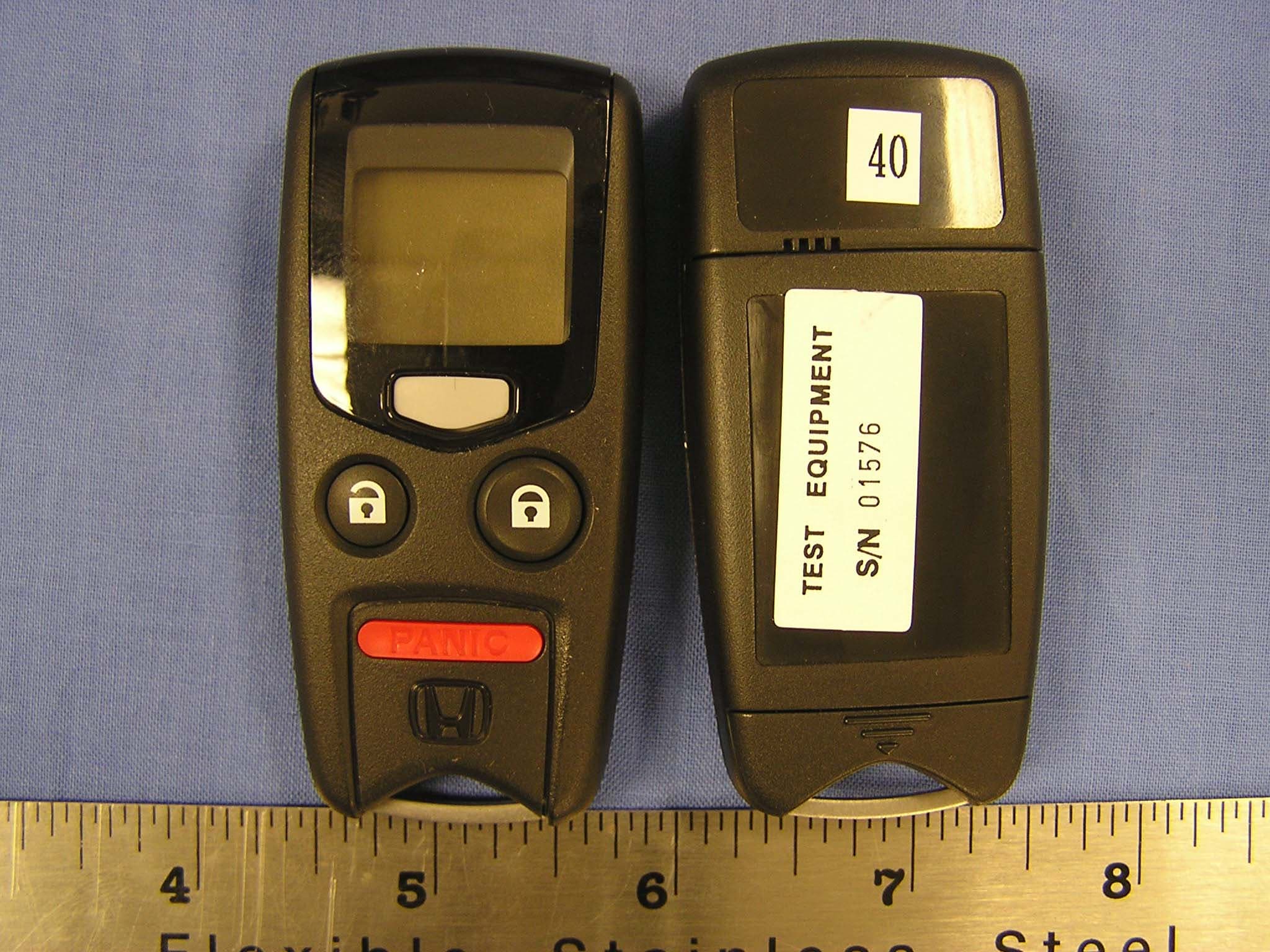
TIC-RS06AC
Aug 24, 2005Remote Control Starter System
Equipment Class
DSR - Part 15 Remote Control/Security Device Transceiver