TIF1CROWN05-MCar Alarm System
Sinew System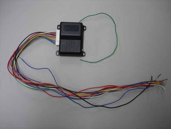
Click to zoom
Application Details
- Equipment Class
- CRR - Superregenerative Receiver
- Date of Grant
- Sep 15, 2005
- Application Purpose
- Original Equipment
- Date of Application
- Sep 15, 2005
- Equipment Note
- Car Alarm System
- Frequency Range
- 433.90000000 - 433.90000000
- Company
- Sinew System
- Country
- South Korea
Documents & Files
Document Text
Text extracted from the exhibit documents filed with the FCC. Open a document above to read the original.
Users Manual
- 1 - AUTO SECURITY SYSTEM MODEL : CR-3000 MANUAL FOR USERS & INSTALLERS Caution : Any changes or modifications in construction of this device which are not expressly approved by the party responsible for compliance could void the user's authority to operate the equipment. FCC statements This device complies with part 15 of the FCC Rules. Operation is subject to the following two conditions: (1) This device may not cause harmful interference, and (2) this device must accept any interference received, including interference that may cause undesired operation. - 2 - CONTROL REMOTE 1. ARM 2. DISARM 3. MUTE ARM 4. MUTE DISARM 1. ARM (LOCK) : Press #1 (±) button 2. DISARM (UNLOCK) : Press #2 (²) button. 3. MUTE ARM : Press #3(T) button, and Press #1 (±) button. 4. MUTE DISARM : Press #3(T) button, and Press #2 (²) button. 5. CHANNEL 2 6. REMOTE PANIC 7. CAR FINDER 5. 2nd CHANNEL (TRUNK) : Press #3(T) button for 3 seconds 6. REMOTE PANIC : Press #1(±) button for 3 seconds 7. CAR FINDER : Press #4(F) button for 2 seconds CHARACTERISTICS a. Alarm with two channels b. Two transmitters with 4 buttons c. Siren of 6 tones of 128dB d. Integrated shock sensor with double (minor/major) protection e. LED indicator f. Two kinds of valet systems with valet switch or transmitter g. Memory system of intrusion h. Arming notification when doors open. i. Siren cancellation by transmitter j. Harness integrated with blade fuses - 3 - CONTENTS a. Main brain with integrated double guard shock sensor b. Two remote controls ( transmitters) c. Harness with blade fuses d. 6-tone siren e. LED indicator f. Valet/ override switch g. Manual for users and installers FUNCTION PROGRAMMING BY INSTALLERS a. Automatic re-arming Æ On / Off (IGN On – Door open - Valet 8 times - #1) b. Automatic (passive) arming Æ On / Off (IGN On – Door open - Valet 8 times - #2) c. Ignition lock / unlock Æ On / Off (IGN On – Door open - Valet 8 times - #3) d. Pulse time of lock / unlock Æ 0.8 sec. / 3.0 sec. (IGN On – Door open - Valet 8 times - #4) e. Double unlock pulseÆ On (Double Unlock) / Off (IGN On – Door open - Valet 8 times - #1 + #2) f. Shock sensor Æ On / Off (IGN On – Door open - Valet 8 times - #3 + #4) g. 2 nd Channel Mode Æ Momentary / Continuous (IGN On – Door open - Valet 8 times - #1 + #3) h. Siren or horn Æ Siren / Horn with Relay (IGN On – Door open - Valet 8 times - #2 +#4) SELECT FUNTION BY USERS a. Mute arm or mute Disarm (#3 - #1 / #3 - #2) b. 2 nd channel (for trunk or sunroof ) (#3 for 3 seconds) c. Remote panic (#1 for 3 seconds) d. Car finder (#4 for 2 seconds ) e. Valet mode with transmitter (door open - IGN On - #4 for 3 seconds On / Off) f. Deletion of shock sensor (IGN On – Door open - Valet switch 8 times - #3 + #4) by transmitter FUNTION’S TABLE OF TRASMITTER BUTTON CONDITIONS FUNTIONS ACTIONS # 1, press one time Ign off + Door closed Arm (after 3 sec.) close securities Siren: 1 chirp Light :1 flash LED: slowly (every 1 sec.) Doors locked Starter disable (block of starter motor) Door opened Notification 3 Chirps #2, press one time Ign off Disarm open securities Siren: 2 chirps Light: 2 flashes LED: off Doors unlocked Starter enable (Triggered) (History) Siren: 4 chirps Light: 4 flashes LED: Rapidly (every 0.5 sec.) # 3, press 3 sec. Ign off 2 nd Channel Trunk, etc # 3 one time - # 1 Ign off Mute arm Arm without sound temporarily # 4 one time Ign off Car finder Siren: 7 chirps Light: 7 flashes # 1 for 3 sec. Ign off Remotepanic Action of Siren+ Light # 3 one time - # 2 Ign off Mute disarm Disarm without sound temporarily # 4 for 3 sec. Door open Ign on Remote valet (for enterance) Siren: 1 chirp for entrance LED: on continuously # 4 for 3 sec. Door open Ign on Remote valet (for exit) Siren: 2 Chirps for exit LED: off - 4 - PROGRAM OF TRANSMITTERS a. Turn ignition on and open a door first and then press Valet/Override switch 4 times (within 15 seconds), then LED will be on continuously and siren will emit 1 long chirp. You are now in the stage of programming mode. b. Press # 1 button then siren will emit 2 short chirps 4 times. c. Turn ignition off. LED will be off and siren will emit 4 chirps. You are now in stage of exiting programming mode. d. You can repeat this and have maximum 4 programmed transmitters per module. If you program new transmitter, we recommend to delete old code memory and to re-program all existing transmitters. You can have this job up to 4 times by same way above. ACTIVATION OF ARMING a. Exit the vehicle and close all entrances. b. Press # 1 button at once. c. Siren chirps 1 time, light flashes 1 time and LED flashes slowly every sec. d. All protected entrances are armed. e. Starter kill enableÆ Starter disables relay which is activated and prevents the engine cranking. f. If any entrance is opened, siren chirps 3 times and LED flashes rapidly for notification. When door is closed, the arming will start. g. After 3 seconds of arming, alarm system will be activated. Shock sensor will not be activated during 3 seconds. It will be re-activated in more than 3 seconds and the sensor becomes stable. ACTIVATION OF DISARMING a. Press #2 button at once. b. Siren chirps 2 times, light flashes 2 times and LED off. c. All protected securities will be disarmed. d. Starter kill disableÆ Start motor can be enabled e. Memory of intrusion: If siren chirps and light flashes 4 times when you disarm the alarm, this notifies alarm has been triggered. Rapid LED flash every 2 times notifies electric security has been triggered, while every 3 times LED flash notifies door had been triggered. MUTE ARMING/ DISARMING a. Press # 3 one time, then press # 1 one time within 3 seconds to enter Mute Arming. b. Press # 3 one time, then press # 2 one time within 3 seconds to enter Mute disarming DEACTIVATION OF EMERGENCY If transmitter is lost or damaged when alarm system is activated arming, following process is needed . Æ Enter Valet Mode first ACC IG OFF STA RT VALET SW -8 -TI MES Open a Door - 5 - a. Turn ignition on. b.…
Text truncated - open the document above for the full version.
Cover Letter(s)
Sinew System Co. 4F,Myeongjin B/D,978-8 Yeongtong-dong, Yeongtong-gu, Suwon-si, Korea 442-812 Tel : 82-31-203-0530 Fax : 82-31-203-0532 E-MAIL : [email protected] Federal Communications Commission 7435 Oakland Mills Road Columbia, MD 21046 Gentlemen: This letter is to comply with Section 0.457(d)(2)(i) pertaining to confidential material Sinew System Co. would like the following documents regarding this submission for FCC ID: TIF1CROWN05-M and TIF1CROWN05-T to be kept confidential. 1. Block Diagram 2. Operating Description 3. Schematic Diagram The above material contains trade secrets or technical data, which would customarily be guarded from competitors. We do not want these documents to be accessible to the general public. Sincerely, Date 27th of July , 2005 By Yo-Cheol Shin Signature Printed Title : President
Cover Letter(s)
Sinew System Co. 4F,Myeongjin B/D,978-8 Yeongtong-dong, Yeongtong-gu, Suwon-si, Korea 442-812 Tel : 82-31-203-0530 Fax : 82-31-203-0532 E-MAIL : [email protected] Federal Communications Commission 7435 Oakland Mills Road Columbia, MD 21046 Gentlemen: I, an officer of Sinew System Co. Do hereby authorize KTL to act on our behalf in front of the Federal Communications Commission with Respect to all matters relating to certification of equipment under Part 15 and Part 18 of the FCC Rules until further notice. I further certify that no party (as defined in 1.2002(b) of CFR 47, 1992) to this application, including myself, is subject to a denial of federal benefits, that include FCC benefits, pursuant to Section 5301 of the Anti-Drug Abuse Act 1988,21 U.S.C., 853(a). Date 27th of July , 2005 By Yo-Cheol Shin Signature Printed Title : President
External Photos
External Photos
Internal Photos
Internal Photos
Test Report
Ref. Report No. This test report only responds to the tested sample and shall not be reproduced except in full without written approval of the Korea Testing Laboratory. Tested and reported by Reviewed by Name and address of the applicant Sinew System Co. 4F, Myeongjin B/D, 978-8, Yeongtong-dong, Yeongtong-gu, Suwon-si, 442-812, Korea Standard / Test regulation FCC Part 15, Subpart B Test result Pass Incoming date : July 27, 2005 Test item(s) ; Superregenerative Receiver (Car Alarm System) Model/type ref. ; CR-3000 Manufacturer ; Sinew System Co. Additional information ; -Required Authorization : Certification -FCC ID. : TIF1CROWN05-M Test date : September 12, 2005 Issue date : September 13, 2005 Jeong-Min Kim, Senior Engineer Won-Seo Cho , Telecommunication Team Manager FG101-01-02-00 222-13, Guro-Dong Guro-Gu Seoul Korea 152-053 http://www.ktl.re.kr Ref. Report No. 05 - 341 – 031 Page 2 of 9 Korea Testing Laboratory Telecommunication Team 222-13, Guro3-dong, Guro-gu, Seoul Korea 152-848 TABLE OF CONTENTS I. GENERAL INFORMATION 3 1. Grantee’s Name and Mailing Address 2. Manufacturer's Name and Mailing Address 3. Equipment Descriptions 4. Rules and Regulations 5. Measuring Procedure 6. Place of Measurement 7. Date of Measurement . GENERAL REQUIREMENTS OF THE EUT 4 1. Labeling Requirement (Section 15.19) 2. Information to User (Sections 15.21) 3. Special Accessories (Section 15.27) . RADIATED EMISSION MEASUREMENT (Section 15.109) 5 1. Test Procedure 2. Photograph for the test configuration 3. Sample Calculation 4. Measurement Data 5. Reference Data . TEST EQUIPMENTS USED FOR MEASUREMENT 9 Ref. Report No. 05 - 341 – 031 Page 3 of 9 Korea Testing Laboratory Telecommunication Team 222-13, Guro3-dong, Guro-gu, Seoul Korea 152-848 . GENERAL INFORMATION 1. Grantee’s Name and : Sinew System Co. Mailing Address 4F, Myeongjin B/D, 978-8, Yeongtong-dong, Yeongtong-gu, Suwon-si, 442-812, Korea 2. Manufacturer's Name and : Sinew System Co. Mailing Address 4F, Myeongjin B/D, 978-8, Yeongtong-dong, Yeongtong-gu, Suwon-si, 442-812, Korea 3. Equipment Descriptions 3.1 Tunning Frequency : 433.9 MHz 3.2 Detect Method : Superregenerative Detector 3.3 Power Supply : DC 12V(Car Battery) 4. Rules and Regulations : FCC Part 15, Subpart B 5. Measuring Procedure : ANSI C63.4-2003 6. Place of Measurement : Absorber-lined Room (KTL) 7. Date of Measurement 7.1 Conducted Emission : Not Applicable 7.2 Radiated Emission : September 12, 2005 Ref. Report No. 05 - 341 – 031 Page 4 of 9 Korea Testing Laboratory Telecommunication Team 222-13, Guro3-dong, Guro-gu, Seoul Korea 152-848 . GENERAL REQUIREMENTS OF THE EUT 1. Labeling Requirement (Section 15.19) This device complies with Part 15 of the FCC Rules. Operation is subject to the following two conditions: (1) this device may not cause harmful interface, and (2) this device must accept any interference received, including interference that may cause undesired operation. 1.1 Location of Label : User’s Guide Manual 1.2 How Applied : Printed 2. Information to User (Section 15.21) The following or similar statements were provided in the manual for user instruction. Please refer page 1 of the attached manual for details. CAUTION : Any changes or modifications in construction of this device which are not expressly approved by the party responsible for compliance could void the user's authority to operate the equipment. 3. Special Accessories (Section 15.27) 3.1 Were the special Accessories provided? [ ] yes, [ x ] no 3.2 If yes, details for the special accessories are as follows : 3.3 If yes, were the appropriate instructions provided on the first page of the text concerned with the installation of the device? [ ] yes, [ ] no 3.4 Are these accessories provided of the type which can be readily obtained from multiple retail outlets ? [ ] yes, [ ] no And therefore does the manual specify what additional components or accessories are required to used in order to comply with the Rules? [ ] yes, [ ] no Ref. Report No. 05 - 341 – 031 Page 5 of 9 Korea Testing Laboratory Telecommunication Team 222-13, Guro3-dong, Guro-gu, Seoul Korea 152-848 . RADIATED EMISSION MEASUREMENT (Section 15.109) 1. Test Procedure 1.1 Preliminary Testing for Reference Preliminary testing was performed in a KTL absorber-lined room to determine the emission characteristics of the EUT. The EUT was placed on the wooden table which has dimensions of 0.8 meters in height, 1 meter in length and 1.5 meters in width. Receiving antenna (Biconi-Log antenna : 30 to 1000 MHz or Horn Antenna : 1 to 18 GHz) was placed at the distance of 1 meter from the EUT. In order to cohere the individual components of the characteristic broadband emission from the receiver(EUT), a RF generator(CW signal) and a log-periodic antenna were used. The frequency and output level of the generator were adjusted for highest observed coherent receiver emissions on the spectrum analyzer with RF amplifier. An attempt was made to maximize the emission level with the various configurations of the EUT. Emission levels from the EUT with various configurations were examined on a spectrum analyzer connected with a RF amplifier and graphed by a plotter. 1.2 Final Radiated Emission Test at an Absorber-Lined Room The final measurement of radiated field strength was carried out in a KTL Absorber-Lined Room that was listed up at FCC according to the "Radiated Emissions Testing" procedure specified by ANSI C63.4. Based on the test results in preliminary test, measurement was made in same test set up and configuration which produced maximum emission level. Receiving antenna was installed at 3-meter distance from the EUT, and was connected to an EMI receiver or spectrum analyzer with a RF amplifier. Turntable was rotated through 360 degrees and receiving antenna height was varied from 1 to 4 meters above the ground plane to read maximum emission level. The maximum emission level from the EUT occurred in such configuration as shown in the following photograph. Ref…
Text truncated - open the document above for the full version.
Test Setup Photos
Test Photos
Contact Information
Applicant
Yo Cheol Shin(President)
Test Firm
Korea Testing LaboratoryJeong-Min Kim
Technical Specifications
| # | Rule Parts | Frequency Range | Power Output |
|---|---|---|---|
| 1 | 15B | 433.9 MHz - 433.9 MHz | - |
Other Applications from Sinew System
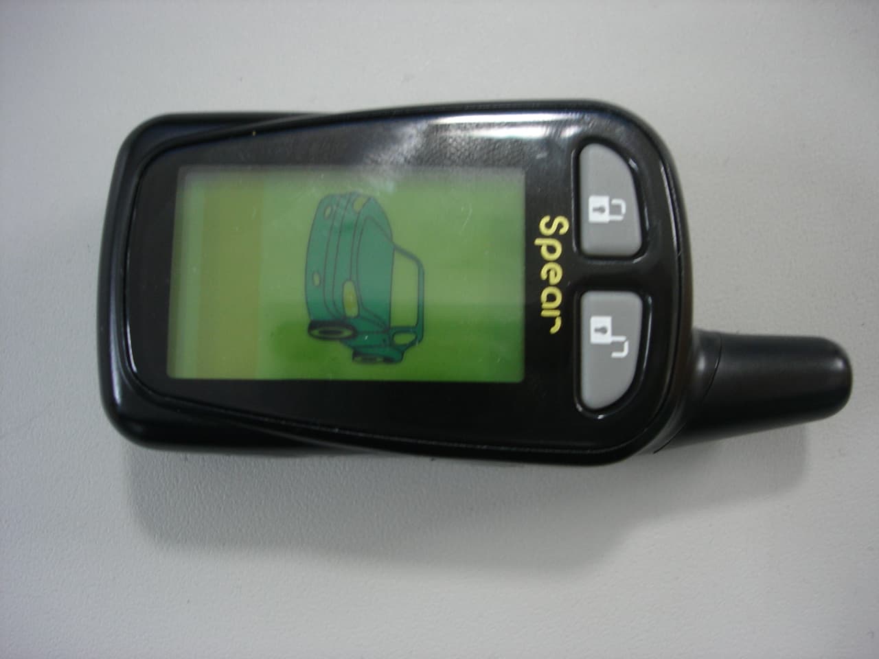
TIF2SPEAR5000RT
Apr 09, 2006Car alarm system
Equipment Class
DSR - Part 15 Remote Control/Security Device Transceiver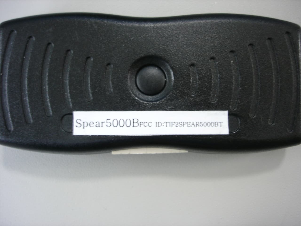
TIF2SPEAR5000BT
Apr 06, 2006Car Alarm System
Equipment Class
DSR - Part 15 Remote Control/Security Device Transceiver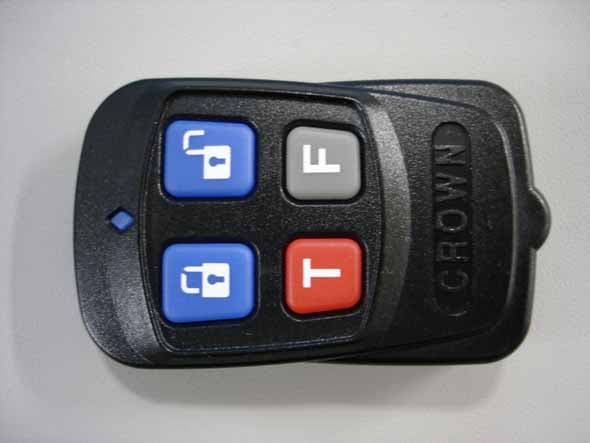
TIF1CROWN05-T
Sep 15, 2005Car Alarm System
Equipment Class
DSC - Part 15 Security/Remote Control Transmitter