TJLMM50LCD Monitor
HEEYOUNG Co., Ltd.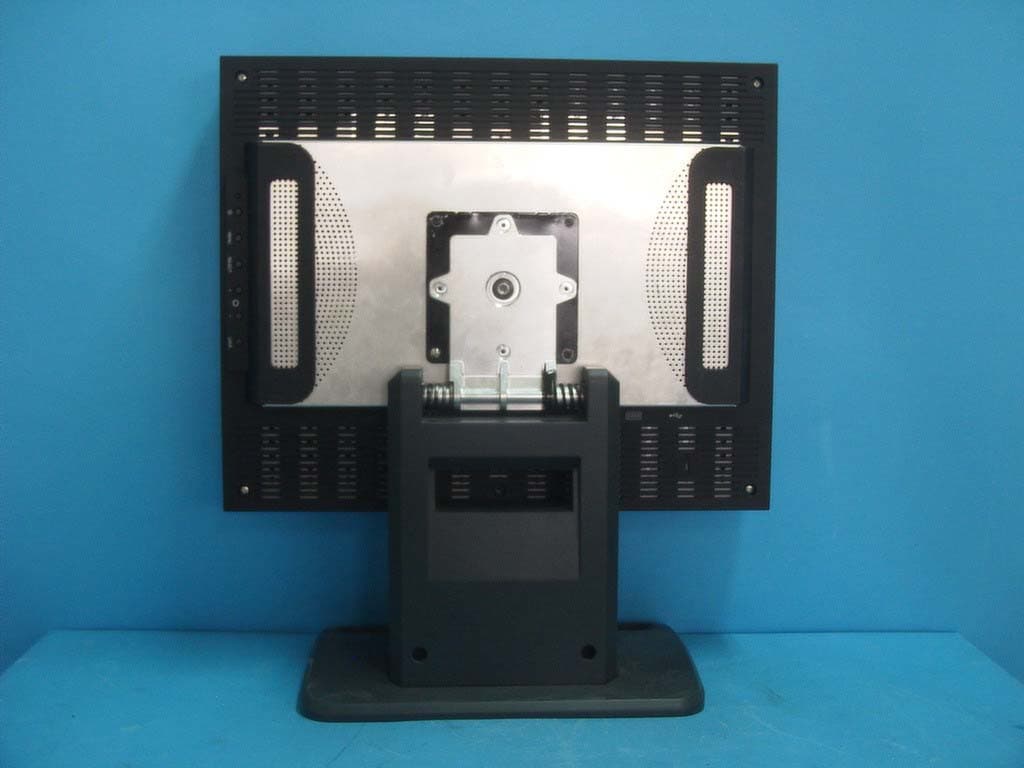
Click to zoom
Application Details
- Equipment Class
- JBP - Part 15 Class B Computing Device Peripheral
- Date of Grant
- Oct 12, 2005
- Application Purpose
- Original Equipment
- Date of Application
- Oct 12, 2005
- Equipment Note
- LCD Monitor
- Company
- HEEYOUNG Co., Ltd.
- Country
- South Korea
Documents & Files
Document Text
Text extracted from the exhibit documents filed with the FCC. Open a document above to read the original.
Users Manual
User’s Manual MM50 1. Safety Instructions --------------------------- 2 2. Regulatory Information --------------------------- 3 3. Precautions --------------------------- 4 4. Before setting up --------------------------- 5 5. Brief specifications of LCD Monitor ------------------------ 6 6. Setting up the LCD Monitor -------------------- 7 1) LCD Monitor’s Connectors -------------------- 7 2) Connecting the LCD Monitor -------------------- 8 7. Adjusting the LCD Monitor --------------------------- 9 1) Adjustment OSD MENU Contents ---------------- 9 2) Adjusting the height and the viewing angle --------- 10 3) Adjustment OSD MENU Contents ---------------- 11 ※ Appendix ----------------------------------- 12 1) DVI-D connector ----------------------- 12 2) Power Management ----------------------- 12 3) Specification ------------------------ 13 4) Trouble shooting ----------------------- 14 5) Contact ----------------------- 14 Contents Symbol Explanation RISK OF ELCTRIC SHOCK DO NOT OPEN CAUTION ! TO REDUCE THE RISK OF ELECTRIC SHOCK, DO NOT REMOVE COVER(OR BACK) NO USER-SERVICEABLE PARTS INSIDE REFER SERVICING TO QUALIFIED SERVICE PERSONNEL MEDICAL EQUIPMENT 13XX E246477 WITH RESPECT TO ELECTRIC SHOCK.FIRE AND MECHANICAL HAZARDS ONLY IN ACCORDANCE WITH UL60601-1, AND CAN/CSA C22.2 NO. 601.1 MEDICAL EQUIPMENT CERTIFIED FOR CANADA Grounding Reliability can only be achieved when the equipment is connected to an equivalent receptacle with marked “Hospital Only” or “Hospital Grade” Explanation of Graphical Symbols Attention, consult ACCOMPANYING DOCUMENTS The lightning flash with arrowhead symbol, within an equilateral triangle ,is intended to alert the be user to the presence of un-insulated ”dangerous voltage” within the product’s enclosure that of may sufficient magnitude to constitute a risk of electric shock to persons Stand-by Switch. Press to turn the monitor on or off(Stand-by mode). Alternating Current Safety Instructions Regulatory Information FCC RF INTERFERENCE STATEMENT This equipment has been tested and found to comply with the limits for a Class B digital device, pursuant to Part 15 of the FCC Rules. These limits are designed to provide reasonable protection against harmful interference in a residential installation. This equipment generates, uses and can radiate radio frequency energy and, if not installed and used in accordance with the instructions, may cause harmful interference to radio communications. However, there is no guarantee that interference will not occur in a particular installation. If this equipment does cause harmful interference to radio or television reception which can be determined by turning the equipment off and on, the user is encouraged to try to correct the interference by one or more of the following measures. - Reorient or relocate the receiving antenna. - Increase the separation between the equipment and receiver. - Connect the equipment into an outlet on a circuit different from that to which the receiver is connected. - Consult the dealer or an experienced radio, TV technical for help. Finally, any changes or modifications to the equipment by the user not expressly approved by the grantee or manufacturer could void the users authority to operate such equipment. For 120Volt applications, use only UL listed detachable power cord with NEMA configuration 5-15P type(parallel blades) plug cap.For 240Volt applications use only UL Listed Detachable power supply cord with NEMA configration 6-15P type(tandem blades) plug cap. CE MARKING DECLARATION OF CONFORMITY This LCD Monitor complies with the reguirements of the EC Directive 89/336/EEC “EMC Directive”and 73/23/EEC “Low Voltage Directive”as amended by Directive 93/68/EEC The electro-magnetic susceptibility has been chosen at a level that gives correct operation in residential areas. Business and light industrial premises and small-scale enterprises, inside as well as outside of the buildings. All places of operation are characterized by connection to the public low voltage power supply system. Classification : - Protection against electric shock : class I - Applied Parts No Applied Parts. - Protection against harmful ingress of water : ordinary IPXO - Mode of operation : Continuous - Degree of safety in the presence of flammable anesthetics mixture with air or with oxygen or with nitrous oxide - Not suitable for use in the presence of a flammable anesthetics mixture with air or with oxygen or with nitrous oxide. 1. Plug the power cord into a properly grounded outlet. There is the risk of electric shock. 2. If you hear a noise or smell smoke from the view box or power cord, unplug the power code immediately, and call service center. There is the risk of electric shock or fire. 3. Do not overload an electrical outlet with too many devices. There is the risk of fire. 4. Do not unplug from the outlet by pulling the power cord or when your hands are wet. 5. Do not bend the power cord excessively or place heavy objects on it. Keep children and pets away from the power cord as they may cause damage the power cord. There is the risk of electric shock or fire. 6. Do not use a damaged power code or plug. Make sure the plug fits snugly into the outlet. There is the risk of electric shock or fire. 7. Do not expose this monitor to the direct sun-light. 8. Do not allow any object or liquid to enter inside this monitor. There is the risk of electric shock, fire, or damage to the monitor. 9. Do not attempt to disassemble, unfix or modify the monitor. There is the risk of electric shock or fire. 10. Keep the monitor away from high temperature, humidity and dust etc.. -> Operating environment : 10~40 degrees Celsius (°C) -> Operating environment : 10~80 relative humidity (%) 11. Use a proper voltage/current level indicated. 12. The device could be send back to the manufacturer for recycling or proper disposal after their useful lives. Alternatively the device shall be disposed in accordance with national laws after the…
Text truncated - open the document above for the full version.
ID Label/Location Info
ID Label Sample & Location Imformation
Test Report
IST Co., Ltd EMC LABORATORY TEST REPORT NO. : 05-IST-0276 1 of 21 Certification of Compliance CFR 47 Part 15 Subpart B Test Report File No. : 05-IST-0276 Date of Issue : Aug 25, 2005 Model(s) : MM50 Kind of Product : LCD Monitor FCC ID : TJLMM50 Applicant : HEEYOUNG Co., Ltd. Address : 1048-8, Shingil-Dong, Danwon-Gu, Ansan-City, Kyunggi-Do, Korea Manufacturer : HEEYOUNG Co., Ltd. Address : 1048-8, Shingil-Dong, Danwon-Gu, Ansan-City, Kyunggi-Do, Korea Test Result ■ Positive □ Negative Reviewed By Approved By S.J.CHO / EMC Group Manager J.H.LEE / Chief Comment(s) - Investigations requested : Measurement to the relevant clauses of FCC rules and regulations Part 15 Subpart B – Unintentional Radiators, Class B. - The test report with appendix consists of 21 pages. - The test result only responds to the tested sample. - It is not allowed to copy this report even partly without the allowance of IST EMC Laboratory. - This equipment as for has been shown to be capable of continued compliance with the applicable technical standards as indicated in the measurement report and was tested in accordance with the measurement procedures specified in ANSI C63.4 2003. IST Co., Ltd EMC LABORATORY TEST REPORT NO. : 05-IST-0276 2 of 21 TABLE OF CONTENTS Table of contents 2 Information of test laboratory, Environmental conditions, Power used, Product information 3 Descriptions of test Conducted Emission 4 Radiated Emission 5 Equipment Under Test 6 Summary 7 ■ Test Conditions and Data - Emissions ◆ Conducted Emissions 0.15MHz - 30MHz Applicable Test Conditions / Data and Plots 8-10 ◆ Radiated Emissions 30MHz - 2GHz Applicable Test Conditions / Data and Plots 11-17 Appendix A. The Photos of Test Setup 18-19 B. The Photos of Equipment Under Test 20-21 Note : IST Co., Ltd EMC LABORATORY TEST REPORT NO. : 05-IST-0276 3 of 21 INFORMATIONS OF TEST LABORATORY EMC LABORATORY of IST Co., Ltd. (FCC Filing Lab.) San 21-8, Goan-Ri, Baekam-Myun, Yongin-City Kyonggi-Do, 449-860, Korea TEL : +82 31 333 4093 FAX : +82 31 333 4094 ENVIRONMENTAL CONDITIONS Temperature 24 °C Humidity 55 % Atmospheric pressure 1008 mbar POWER SUPPLY SYSTEM USED Power supply system AC 120Vac, 60Hz (Refer to the product information) PRODUCT INFORMATION - EMC suppression device is not used during the test . - Please refer to user’s manual. - Model Name : MM50 FCC ID : TJLMM50 Pannel : Size – 20.1” Type – a-si TFT Active matrix Display Size – 399(H)x319(V) mm Brightness – 850cd/㎡ Pixel Pitch – 0.156mm x 0.156mm Contrast Ratio – 600:1 Resolution : Landscape – 2560 x 2048, Portrait – 2048 x 2560 Digital Interface : DVI-D Connector USB Port : 1Up stream, 2Down stream Power : 100-240Vac, 50/60Hz, 75W Dimension(mm) : 438(W) x 458(H) x 98(D) IST Co., Ltd EMC LABORATORY TEST REPORT NO. : 05-IST-0276 4 of 21 < Concept Drawing > 215 >150 >40 80 Receiver EUT LISN 80 ≥ 80 80 40 ≥ 80 Measuring apparatus Mains Filter Mains Rear side Equipment under test Coaxial cable Artificial mains networ k Screened room Non-metallic support 80 DESCRIPTIONS OF TEST Conducted Emissions: The measurement were performed over the frequency range of 0.15MHz to 30MHz using a 50 Ω /50uH LISN as the input transducer to a Spectrum Analyzer or a Field Intensity Meter. The measurements were made with the detector set for "Peak" amplitude within a bandwidth of 10KHz or for "quasi-peak" & “Average” within a bandwidth of 9KHz. - Procedure of Test The line-conducted facility is located inside a shielded room No.1. A 1m X 1.5m wooden table 80cm height is placed 40cm away from the vertical wall and 1.5m away from the other wall of the shielded room. The R/S ESH3 and Hyup-Rip KNW-407 LISN are bonded to bottom of the shielded room. The EUT is located on the wooden table with distance more than 80cm from the LISN and powered from the EMCO LISN .The peripheral equipment is powered from the other LISN. Power to the LISNs are filtered by a noise cut power line filters. All electrical cables are shielded by braided tinned steel tubing with inner φ 1.2cm. If the EUT is a DC-powered device, power will be derived from the source power supply it normally will be powered from and this supply lines will be connected to the EMCO LISN. All interconnecting cables more than 1m were shortened by non-inductive bundling to a 1m length. Sufficient time for the EUT, support equipment, and test equipment was allowed in order for them to warm up to their normal operating conditions. The RF output of the LISN was connected to the R/S receiver to determine the frequency producing the maximum emission from the EUT. The frequency producing the maximum level was reexamined using Quasi-Peak mode by manual measurement, after scanned by automatic Peak mode for frequency range from 0.15 to 30MHz. The bandwidth of the receiver was set to 10kHz. The EUT, peripheral equipment, and interconnecting cables were arranged and manipulated to maximize each EME emission. < Side View > IST Co., Ltd EMC LABORATORY TEST REPORT NO. : 05-IST-0276 5 of 21 DESCRIPTION OF TEST Radiated Emissions: The measurement was performed over the frequency range of 30MHz to 1GHz using antenna as the input transducer to a Spectrum analyzer or a Field Intensity Meter. The measurement was made with the detector set for "quasi-peak" within a bandwidth of 120KHz. - Procedure of Test Preliminary measurements were made at 3 meter using bi-conical and log-periodic antennas, and spectrum analyzer to determine the frequency producing the max. emission in anechoic chamber. Appropriate precaution was taken to ensure that all emission from the EUT were maximized and investigated. The system configuration, mode of operation, turn-table azimuth and height with respect to the antenna were noted for each frequency found. The spectrum was scanned from 30MHz to 300MHz using S/B bi-conical antenna and 300 to 1000MHz using S/B log-periodic antenna. Above 1GHz, linearly polarized double ridge horn antennas were used. Final measurements were made at open site with 3-meters test d…
Text truncated - open the document above for the full version.
Contact Information
Applicant
Kwoang Su Yun(Director)
Test Firm
IST Co., LtdBong Kyoon Bae
Technical Specifications
| # | Rule Parts | Frequency Range | Power Output |
|---|---|---|---|
| 1 | 15B | - | - |
Other Applications from HEEYOUNG Co., Ltd.
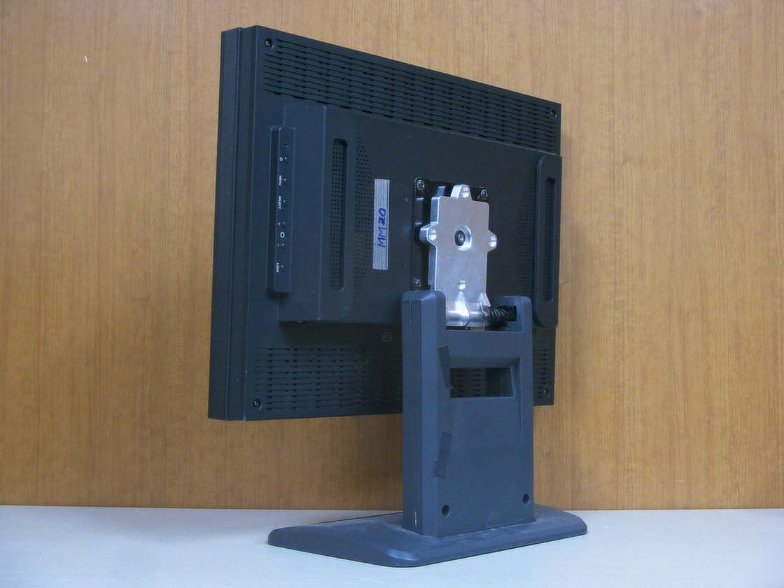
TJLMM20
Oct 14, 2005LCD Monitor
Equipment Class
JBP - Part 15 Class B Computing Device Peripheral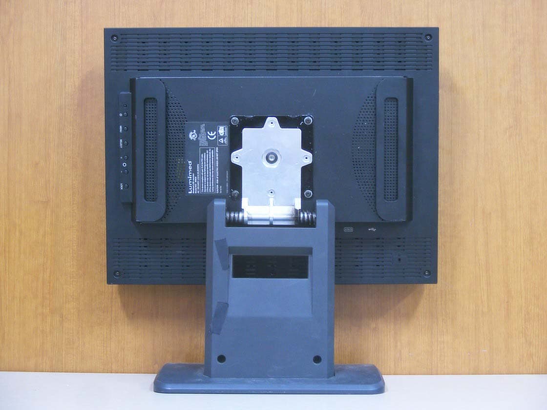
TJLMM30
Oct 14, 2005LCD Monitor
Equipment Class
JBP - Part 15 Class B Computing Device Peripheral