TJV-F4E60F92Voice communication system
FREQUENTIS USA Inc.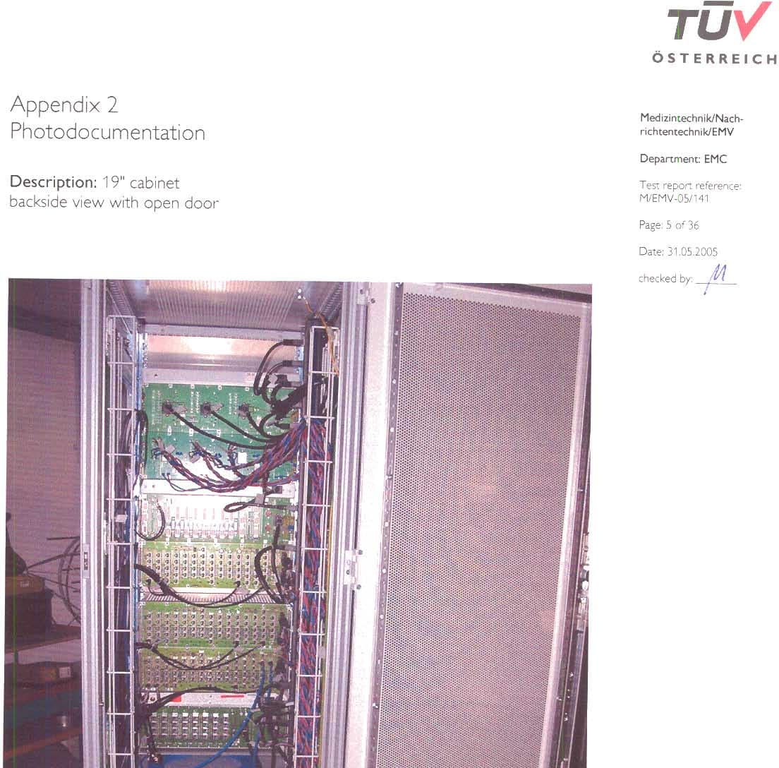
Click to zoom
Application Details
- Equipment Class
- JBC - Part 15 Class B Computing Device/Personal Computer
- Date of Grant
- Sep 05, 2005
- Application Purpose
- Original Equipment
- Date of Application
- Sep 05, 2005
- Equipment Note
- Voice communication system
- Company
- FREQUENTIS USA Inc.
- Country
- United States
Documents & Files
Document Text
Text extracted from the exhibit documents filed with the FCC. Open a document above to read the original.
Users Manual
Voice Communication System VCS 3020X Rel. 4.1 Short User Manual 04A28 E502.10 © FREQUENTIS 2004 Legend 1 1 Procedure step number. Press the key or take another action. ! Action leads to a reaction. or Introduces an alternative action or reaction. = Stands for, equals. Symbol for incoming chime tone (for details on all other tones refer to the User Manual VCS 3020X Rel. 4.1, Doc.No. 04A28 E501). WARN Symbol for special tones (for details refe r to the User Manual VCS 3020X Rel. 4.1). , Press PTT, release PTT. CHIME Yes Key text/names (in this example for a function key or sub-menu key). Key is unavailable for activation. Key is idle and available for activation. Key is transient, i.e. blinking between available and active. Key is active. 40 Messages on a display. Before You Start 2 1 2 3 4 5 6 7 Are your headset/handset and/or your microphone connected to the plug-in panel? Are incoming telephone calls signalled? Check whether CHIME is active or idle - it turns the acoustic indication on and off. Can telephone communication be heard via headset or loudspeaker? Check whether DAI LS , MASTER LS , GG LS are active or idle - they route audio either to loudspeaker or headset. Can radio communication be heard via headset or loudspeaker? Check the LSP toggle key on the frequency control window. Check if AG LS is active or idle - it routes audio either to loudspeaker or headset. Press PAGE to scroll cyclically through the pages available on your panel. Scroll through to become familiar with them and see what the operational area looks like. If you have two panels at your operator position, pre ss SPLIT to activate split position operation. Works only, if split position is enabled on the TM CS, and at least one headset is connected. Result: there is radio and telephone operation on one pan el, and telephone operation with radio status indication on the other. Press SET to open the settings window for brightness and volume control. Layout 3 Main Page Display area Function keys Telephone keys Select a DA-layer or the phone book Function keys Incoming call queue & active call display Radio keys End key Settings on the Touch Panel 4 Main Page On the main page press SET to open the settings window. Settings Window Accept new configurations or reset original ones. Panel calibration carried out by ma intenance staff. Clean the touch panel screen. Move sliders to adjust: - volume levels - A/G-G/G-balance - panel brightness Function Keys 5 Main Page Alphabetical list of function keys: AIR/GROUND LOUDSPEAKER: for routing all A/G-audio to a loudspeaker (toggle between headset and loudspeaker) Key carries the NAME of the ACTIVE ROLE ; for accepting a new layout/role during panel reconfiguration CHIME TONE SINGLE OR STEADY: for toggling between single and steady chime (default: CCB active) CHIME: for toggling the chime for incomi ng call indicati on between ON/OFF CLIR: for activating CLIR, i.e. inhibit your identity during an active ISDN-call CONFERENCE: for telephone conference calls CUT-IN: for monitoring and interrupting calls on other operator positions (supervisors only) DIRECT ACCESS INTERCOM LOUDSPEAKER: for routing DAI-audio to a loudspeaker (toggle between headset and loudspeaker) DIAL PAD: for opening the dial pad DIVERSION: for diverting all telephone calls to another operator position DOOR: for activating the door opener DROP: for releasing the last party in a conference call Function Keys 6 FAST COUPLING: for coupling all frequencies in Tx-mode with one touch FREQUENCY FORWARDING: for forwarding frequencies to another operator position FREQUENCY INTERCOM: for direct communication to all posi tions having frequencies in traffic or monitor mode GROUND/GROUND LOUDSPEAKER: for routing G/G-audio to loudspeaker (toggle between headset and loudspeaker) HOLD: for holding active telephone calls HOOK FLASH SIGNAL: for sending a hook flash signal to an external open line LESS: for switching from the second layer of function keys back to the first layer MAN RING: for sending a ringing signal for a defined period MASTER LOUDSPEAKER: for routing all audio to a loudspeaker (toggle between headset and loudspeaker) MONITORING: for position monitoring MORE: for switching to the second row of function keys LOUDSPEAKER OVERRIDE: for overriding the automatic tr ansfer of A/G-audio to LS during G/G- communication PAGE: for scrolling through the panel pages Function Keys 7 PICK-UP: for picking up pending calls from other operator positions PLAY BACK: for opening the play-back window POSITION CONFIDENCE CHECK: for activating a hardware test of the operator position PRIORITY: for increasing the priority of a telephone call PRIVACY MODE: for protecting supervisor positions from monitoring RELIEF BRIEFING: for activating a two-way communication between coach and trainee RUNWAY INCURSION: for toggling the function between ON and OFF SETTINGS window: for opening the setting windows SPLIT POSITION: for splitting an operator positi on for separate A/G- and G/G-use SUBSTITUTE: for substituting another operator position, i. e. taking over incoming calls from there TRANSFER: for transferring an active call to another party WIRELESS: for answering calls with your wireless telep hone while you are not at your operator position END: for terminating telephone calls and certain functions Telephone: Key States 8 Key is unavailable for activation. DA: Direct Access Key is idle, and available for activation. Key is deselected; there is no acoustic indication for incoming calls. Symbol shows that interface for wireless telephone call activated, incoming calls are redirected to wireless phone. Symbol shows that you act as substitute for this operator position. Key is blinking between idle and active; shows an incoming direct access call (DA) on a DA-key, or in the incoming call queue (configurable). Background active; key shows an ac tive direct access call (DA). CA: Common Answer Key is blinking between idle and active; shows an incoming …
Text truncated - open the document above for the full version.
Users Manual
FREQUENTIS SAFETY GUIDELINES 00A46 E500.12 COPYRIGHT FREQUENTIS 2000 FREQUENTIS GmbH Spittelbreitengasse 34, A-1120 Vienna, DVR 0364797 D-1File: SGL REV.1.2.DOCFREQUENTISSAFETY GUIDELINES No: 00A46 E500.12Author: S. MeiselCOPYRIGHT FREQUENTIS 2000 History Chart Rev. DateChanged Page(s)Cause of ChangeImplemented 1.000-11-29All sectionsNew DocumentS. Meisel 1.101-07-20All sectionsWording & CorrectionsS. Meisel 1.204-02-01D-1, 5, 6, 8, 9, 34, 35UL- & EN-Requirements; VCS >> "system" S. Meisel No. ActionNameSignatureDateDepartment 1PreparedS. Meisel04-07-12TCI 2 Approved G. Herndl 04-07-16 SSG 3ApprovedH. Schicht04-07-13TQC 4 Released F. Kalwitz 04-07-16 TCI The information in this document is subject to change without notice. All rights reserved. No part of the document may be reproduced or transmitted in any form or by any means, electronic or mechanical, for any purpose, without the written permission of FREQUENTIS GmbH. Company or product names mentioned in this document may be trademarks or registered trademarks of their respective companies. Confirmed by the CE-label, the system complies with following EC-directives and EC-standards: ● 73/23/EC “Low Voltage” ● 89/336/EEC “Electromagnetic Compatibility” ● 99/5/EC “R&TTE” (Annex 2 Class I Equipment) ● EN 60950-1 (01) ● EN 55022 (98) ● EN 55024 (98) The system complies with Part 15 of the FCC Rules. Operation is subject to the following 2 conditions: (1) this device may not cause harmful interference, and (2) this device must accept any interference received, including interference that may cause undesired operation. SAFETY GUIDELINESFREQUENTISFile: SGL REV.1.2.DOCC-2 COPYRIGHT FREQUENTIS 2000Author: S. MeiselNo: 00A46 E500.12 Contents 1.Introduction .......................................................................... 4 1.1.Purpose............................................................................................................. 4 1.2.Target Group..................................................................................................... 4 1.3.Requirements Concerning Warranty ................................................................. 4 1.4.Description of the Warning Symbols ................................................................. 5 1.5.Definition of Terms and Synonyms ................................................................... 6 1.6.Major Warnings ................................................................................................. 6 2.Safety Instructions ............................................................... 7 2.1.Safety-Critical Phases of Installation and Maintenance .................................... 7 2.2.Personal Safety................................................................................................. 8 2.2.1.Fire Hazard ....................................................................................................... 8 2.2.2.Electric Shock ................................................................................................... 8 2.2.2.1.Causes and Prevention of Electric Shock ......................................................... 9 2.2.2.2.Inspection to Prevent Electric Shock............................................................... 10 2.2.3.Injuries............................................................................................................. 11 2.3.Handling Safety............................................................................................... 11 2.4.Equipment Safety ............................................................................................ 12 2.4.1.Mechanical Requirements............................................................................... 12 2.4.2.Electrical Requirements .................................................................................. 13 2.4.2.1.Safety Requirements....................................................................................... 13 2.4.2.2.Redundancy Requirements (if applicable) ...................................................... 14 2.4.2.3.Protective Earthing.......................................................................................... 15 3.Electrostatic Discharge (ESD) .......................................... 16 3.1.Definition ......................................................................................................... 16 3.2.ESD-Protection of Sensitive Assembly Parts .................................................. 16 3.3.Handling of Devices Sensitive to Electrostatic Discharge ............................... 17 3.3.1.General Rules for Handling Electronic Assemblies......................................... 17 3.4.ESD-protection at the Equipment Area ........................................................... 17 3.5.ESD-Protected Workplace .............................................................................. 19 3.6.ESD-Protection during Shipping and Storage ................................................. 20 3.6.1.Packaging of Electronic Assemblies ............................................................... 20 3.7.ESD-Regulations for Visitors........................................................................... 20 4.Overvoltage Caused by Electrical Transients / Lightning. 21 5.Electromagnetic Compatibility (EMC) .............................. 22 5.1.Generic Electromagnetic Compatibility Requirements .................................... 22 5.2.Specific Electromagnetic Compatibility Requirements .................................... 22 5.2.1.Electromagnetic Fields Emitted by Visual Display Units ................................. 23 5.2.2.Check of Aerials and Receivers Adjacent to the Equipment ........................... 23 C-3File: SGL REV.1.2.DOCFREQUENTISSAFETY GUIDELINES No: 00A46 E500.12Author: S. MeiselCOPYRIGHT FREQUENTIS 2000 6.Equipment Labelling .......................................................... 24 6.1.Adhesive FREQUENTIS Equipment Labels ......................…
Text truncated - open the document above for the full version.
Cover Letter(s)
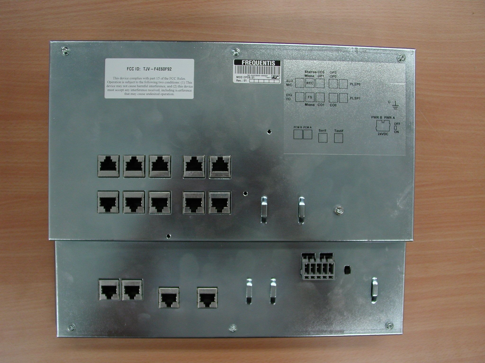
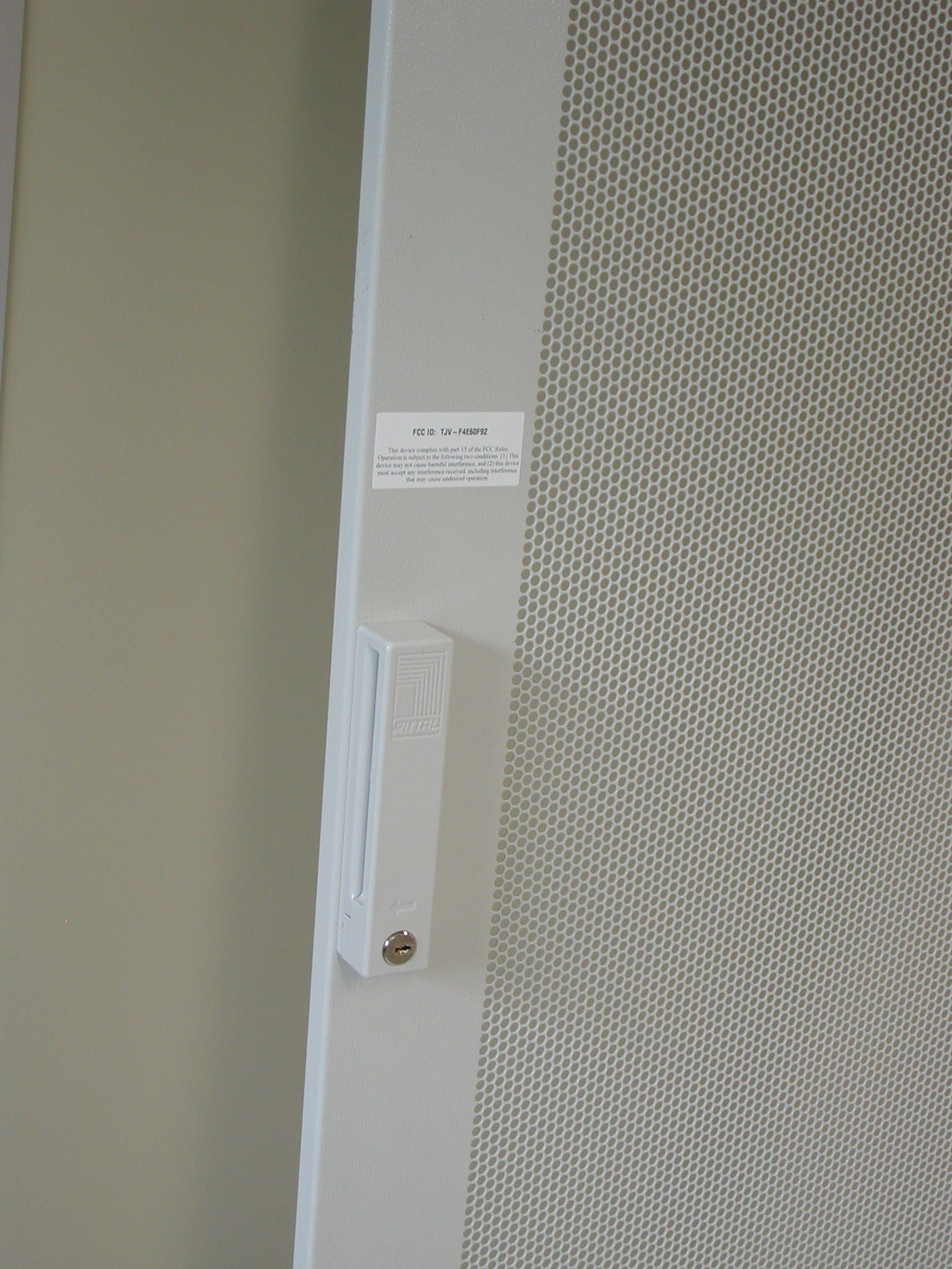
Coverletter: FREQUENTIS USA, Inc. wants to get FCC-Certification for the following product: Voice communication system built into a 42HE 19" cabinet plus operator positions The system will get the following FCC-ID: TJV-F4E60F92 List of documents: Exhibit Thema File Exhibit 01 Label and placement FCC_Label_mit_ID.pdf EPSN0001.jpg EPSN0006.JPG Exhibit 02 Not needed -------------------- Exhibit 03 External Photos extern_05-141.pdf * Exhibit 04 Block Diagrams 1HUS_Block_Diagramm.pdf BCA0300_Block_Diagramm.pdf BCB0300_Block_Diagramm.pdf BGT_CIF5_Block_Diagramm.pdf BGT_CIF_Block_Diagramm.pdf BGT_IF2000S_Block_Diagramm.pdf BGT_PS01_Block_Diagramm.pdf ERIF_0301_Block_Diagramm.pdf GPIF0301_Block_Diagramm.pdf JIF5_Block_Diagramm.pdf LB0300_Block_Diagramm.pdf RSIF0300_Block_Diagramm.pdf T00300_Block_Diagramm.pdf * Exhibit 05 Schematic Diagrams 1HUS_Schematic.pdf BCA0300_Schematic.pdf BCB0300_Schematic.pdf BGT_CIF2_Schematic.pdf BGT_CIF5_Schematic.pdf BGT_CIF_Schematic.pdf BGT_IF2000S_Schematic.pdf BGT_PS01_Schematic.pdf BGT_UIF_Schematic.pdf CPOS_Schematic.pdf EPOSA_Schematic.pdf ERIF0300_Schematic.pdf GPIF0301_Schematic.pdf JIF5_Schematic.pdf LB0300_Schematic.pdf PIPA_Schematic.pdf PIPS_Schematic.pdf PLSP_Schematic.pdf POT_Schematic.pdf RSIF0300_Schematic.pdf T00300_Schematic.pdf Exhibit 06 Testreport 05-141_part1.pdf 05-141_part2.pdf Exhibit 07 Test Set-up Photos setup_05-141.pdf Exhibit 08 User Manual 04A28E502_10_ShortUMan.pdf SGL Rev.1.2.pdf Exhibit 09 Internal Photos intern_05-141.pdf Exhibit 10 Not needed ---- Exhibit 11 Not needed ---- *Exhibit 12 Operational Description 04A28E505_11_SPD.pdf Exhibit 13 Cover letter Request for confidentiality This file FCC_confidentiality_signed.pdf For the Exhibits marked with ‘*’ FREQUENTIS USA, Inc. requested Confidentiality according to 47 CFR 0.457 and 0.459 of the FCC rules because these are sensitive parts owned by this company and include much of Know-How or sensitive data, it will not be provided to the public. The labelling on some photos may not be the actual status. The correct labelling you can find in Exhibit 1.
Contact Information
Applicant
Robert Nitsch(Vice President)
Technical Contact
Test Firm
TUV AustriaIng Wilhelm Seier
Technical Specifications
| # | Rule Parts | Frequency Range | Power Output |
|---|---|---|---|
| 1 | 15B | - | - |