TLC-84941XXTransmitter
SHURflo, LLC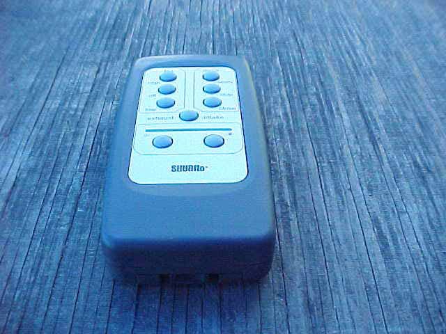
Click to zoom
Application Details
- Equipment Class
- DSC - Part 15 Security/Remote Control Transmitter
- Date of Grant
- Dec 01, 2005
- Application Purpose
- Original Equipment
- Date of Application
- Dec 01, 2005
- Equipment Note
- Transmitter
- Frequency Range
- 434.00000000 - 434.00000000
- Company
- SHURflo, LLC
- Country
- United States
Documents & Files
Document Text
Text extracted from the exhibit documents filed with the FCC. Open a document above to read the original.
Users Manual
Thank you for purchasing this fan from SHURflo. Please take a few minutes to read this entire manual before attempting installation. If you have any questions, please contact your nearest dealer or SHURflo. This unit will work at an infinite range of speeds in automatic or manual modes at a wide range of temperature settings. Automatic dome-sensing control allows it to work with most vent covers. Automatic shut-off when it’s raining and motor thermal protection are just a couple of the exciting safety features of this fan. Standard Features • True Variable Speed Fan • Easy-Remove Screen • Fits Standard 14” x 14” Roof Openings • Thermally Protected Motor • High-Amp Dome Safety Control • Remote-Control • Intake & Exhaust Operation • Motorized Dome • Automatic Rain Sensor • Auto-Temp Control from 60°F – 100°F Contents • 1 Comfort Air™ Fan Unit, including -1 upper unit -1 internal flange & 4 screws o Supplied trim fits roofs 3-1/2”-5-1/4” See specifications on page 4 for trim model # for other roof sizes • 1 Remote Control • 1 Remote Wall Mount & 2 screws • 1 9-Volt DC Remote Control Battery • 1 Installation and Operation Manual Location • Fan must be installed with the hinge facing the direction of travel. • Locate bi-directional fan at least 3 feet from any exhaust vent. l Do not install fan in cooking area. Important Information • SHURflo recommends professional installation. • Please read the entire manual before attempting installation. • This unit requires 12 VDC Power only. • This fan uses 5 Amps. Use 6A fuse. • Follow all local building / electrical codes. • Black wire is negative ground [ - ]. • Red wire is positive power [ + ]. • Never reverse polarity. Reverse polarity can damage circuit board. • Never turn the fan on with the screen removed. • Always turn off power before removing screen. • Never place any objects in moving blade path. Tools and Materials Required • #2 Philips screwdriver • Scraper • Wire stripper/crimp tool • Butyl sealing tape (1/8” x 1” x 6’) • 18 Gauge or larger copper stranded wire • Insulated wire connectors • 6-Amp fused circuit • All weather Silicone sealant ---Rubber roofs require EPDM sealant • 3/4” or 1” x #8 self-tapping screws [ 28 ] for roof mounting. Screws removed from old unit can be used. Comfort Air™ Fan with Remote Installation and Operation Manual Models 275-3330 / 275-3331 911-724-A 04/05 page 1 of 4 ! ! jFan Hi Fan Speed Increase + Press this button to increase fan speed. kFan Off Fan Stop & Power Off Press this button to stop the fan in Manual. Press this button to exit Auto Mode [fan will stop and dome will close]. lFan Lo Fan Speed Decrease – Press this button to decrease fan speed. mDome Open Press this button to Open the Dome. nDome Stop Press this button to Stop the Dome. oDome Close Press this button to Close the Dome. pExhaust / Intake Press this button to change fan direction. Thermostat Control & LED Light Bank Adjust fan temperature from 60°F [green lights] to 100°F [red lights] Remote Reset Left green light and right red light are used when resetting the remote control. See Section on Resetting The Remote. qCooler ( Auto Mode ) Press this button to set fan in Auto mode and to lower the thermostat temperature setting rWarmer ( Auto Mode ) Press this button to set fan in Auto mode and to raise the thermostat temperature setting sBattery Compartment ( Rear of Remote ) Slide open rear compartment to replace 9V battery. Resetting The Remote Never reset remote control with screen removed. It may be necessary at times to reset the remote to match the Comfort Air™ unit. This would be done to make one remote work for 2 fans, to make 2 fans operate from different remotes, or when purchasing a new remote for an installed unit. To reset the remote to a fan unit: 1. Press and hold FAN OFF [ k ], until green and red lights blink [about 10 seconds]. 2. WITHOUT RELEASING FAN OFF Button ] k ], press the Reset Button on the fan unit [see fan picture]. 3. Hold buttons until fan motor goes into high speed. Fan unit is now reset to this remote. To avoid resetting 2 fans at the same time, completely turn off the power to the fan you do not want to reset. COMFORT AIR™ FAN REMOTE COMMANDER j k l m n o p s q r 911-724-A 04/05 page 2 of 4 NOTICE: Unit will not operate without remote. If remote is lost or damaged, turn power off and close dome with hand crank. Call your dealer or SHURflo for a replacement remote control. Rear of Remote ! Installation 1. Turn off all power to fan. 2. If it is a new installation, cut and frame out a 14” x 14” hole. Prepare all wiring and fusing per specifications. 3. Remove old fan inside and out. 4. Carefully remove all old roof sealant. Surface must be clean and dry. 5. Check fit of new fan inside and out. --Hinge must face toward front of the RV. --Verify correct wiring size and length. --Check inside ceiling flange clearance. Supplied trim fits roofs 3-1/2” to 5-1/2” thick. Trim can be cut or call SHURflo for other sizes --Holes in roof exterior can be filled with wood putty or sealant to ensure a better seal later. 6. Apply 1” Butyl putty tape around mounting hole pattern on roof side of fan chassis. --Center the tape over the mounting holes. 7. Place unit on roof and check alignment inside and outside. --Hinge must be to the front of the RV. 8. Screw unit to roof with 28 screws. --Screws removed from previous unit can be used. 9. Seal all edges and screws with silicone sealant, or use EPDM Rubber roof sealant for rubber roofs. --Do not allow sealant to contact dome hinge or rain sensor. 10. Check wire polarity and connect wires inside of coach. --Red wire is positive (+). --Black wire is negative (-). --Polarity must be correct or damage to circuit board will result! 11. Test hand crank by pulling down on crank and turning CW to open dome. --Crank must be in upper position for power operation. --Dome motor must be stopped before moving hand crank in or out. 12. Place lower trim in place and secure with 4 screws provid…
Text truncated - open the document above for the full version.
Cover Letter(s)
Correspondence by Project Project Number: 2145501653 Correspondence Number Memo TLC-84941XX-1 1) Please provide a diagram of where the FCC ID label will be placed on the device. Response: The FCC ID Label Exhibit has been revised to include the label location on page 2. 2) In the test report, the FCC ID mentioned is SPJ84-940-XX, which is not the same as the FCC ID in the application. Please confirm the FCC ID to be used for this device and correct the test report as appropriate. Response: The Test Report has been revised to show the correct FCC-ID of TLC-84941XX. 3) A modification is mentioned in the test report, but there was no modification letter uploaded with the application. Please upload a letter stating the modifications that were done and that they will be implemented in the final production of the device. Response: The modification letter was not uploaded originally. It has now been uploaded. 4) In the test report, it is mentioned that (2) 6pf capacitors are placed at the onset of the antenna and coupled to the PCB ground, this also appears to be shown in the internal photos. However, the schematics show only one capacitor between the antenna and PCB ground. Please clarify and provide the corrected schematics or test report. Response: The EUT has been re-tested with only (1) 6pf capacitor -- the unit matches what the schematics show. External and Page 1 of 2Untitled Document 11/23/2005http://www.celectronics.com/CorrespondenceByProject.asp?ProjectNumber=2145501653... Internal have been revised along with the test report. Please see the exhibits. Page 2 of 2Untitled Document 11/23/2005http://www.celectronics.com/CorrespondenceByProject.asp?ProjectNumber=2145501653...
Test Report
Report Number: B50310A1 FCC Part 15 Subpart B and FCC Section 15.231 Test Report Transmitter Model: 84-941-XX 114 OLINDA DRIVE, BREA, CALIFORNIA 92823 PHONE: (714) 579-0500 FAX: (714) 579-1850 Page 1 of 15 FCC PART 15, SUBPART B and C TEST REPORT for TRANSMITTER MODEL: 84-941-XX Prepared for SHURflo, LLC 5900 KATELLA AVENUE CYPRESS, CALIFORNIA 90630 Prepared by:_____________________ JAMES ROSS Approved by:____________________ KYLE FUJIMOTO COMPATIBLE ELECTRONICS INC. 114 OLINDA DRIVE BREA, CALIFORNIA 92823 (714) 579-0500 DATE: NOVEMBER 22, 2005 REPORT APPENDICES TOTAL BODY A B C D E PAGES 15 2 2 2 12 16 49 This report shall not be reproduced except in full, without the written approval of Compatible Electronics. Report Number: B50310A1 FCC Part 15 Subpart B and FCC Section 15.231 Test Report Transmitter Model: 84-941-XX 114 OLINDA DRIVE, BREA, CALIFORNIA 92823 PHONE: (714) 579-0500 FAX: (714) 579-1850 Page 2 of 15 TABLE OF CONTENTS Section / Title PAGE GENERAL REPORT SUMMARY 4 SUMMARY OF TEST RESULTS 4 1. PURPOSE 5 2. ADMINISTRATIVE DATA 6 2.1 Location of Testing 6 2.2 Traceability Statement 6 2.3 Cognizant Personnel 6 2.4 Date Test Sample was Received 6 2.5 Disposition of the Test Sample 6 2.6 Abbreviations and Acronyms 6 3. APPLICABLE DOCUMENTS 7 4. DESCRIPTION OF TEST CONFIGURATION 8 4.1 Description of Test Configuration - EMI 8 4.1.1 Cable Construction and Termination 9 5. LISTS OF EUT, ACCESSORIES AND TEST EQUIPMENT 10 5.1 EUT and Accessory List 10 5.2 EMI Test Equipment 11 6. TEST SITE DESCRIPTION 12 6.1 Test Facility Description 12 6.2 EUT Mounting, Bonding and Grounding 12 7. TEST PROCEDURES 13 7.1 Radiated Emissions (Spurious and Harmonics) Test 13 7.2 Bandwidth of the Fundamental 14 8. CONCLUSIONS 15 Report Number: B50310A1 FCC Part 15 Subpart B and FCC Section 15.231 Test Report Transmitter Model: 84-941-XX 114 OLINDA DRIVE, BREA, CALIFORNIA 92823 PHONE: (714) 579-0500 FAX: (714) 579-1850 Page 3 of 15 LIST OF APPENDICES APPENDIX TITLE A Laboratory Recognitions B Modifications to the EUT C Additional Models Covered Under This Report D Diagrams, Charts, and Photos • Test Setup Diagrams • Radiated Emissions Photos • Antenna and Effective Gain Factors E Data Sheets LIST OF FIGURES FIGURE TITLE 1 Plot Map And Layout of Radiated Test Site Report Number: B50310A1 FCC Part 15 Subpart B and FCC Section 15.231 Test Report Transmitter Model: 84-941-XX 114 OLINDA DRIVE, BREA, CALIFORNIA 92823 PHONE: (714) 579-0500 FAX: (714) 579-1850 Page 4 of 15 GENERAL REPORT SUMMARY This electromagnetic emission test report is generated by Compatible Electronics Inc., which is an independent testing and consulting firm. The test report is based on testing performed by Compatible Electronics personnel according to the measurement procedures described in the test specifications given below and in the "Test Procedures" section of this report. The measurement data and conclusions appearing herein relate only to the sample tested and this report may not be reproduced without the written permission of Compatible Electronics, unless done so in full. This report must not be used to claim product endorsement by NVLAP, NIST or any other agency of the U.S. Government. Device Tested: Transmitter Model: 84-941-XX S/N: N/A Product Description: See Expository Statement. Modifications: The EUT was modified in order to meet the specifications. Please see the list located in Appendix B. Manufacturer: SHURflo, LLC 5900 Katella Avenue Cypress, California 90630 Test Date: November 22, 2005 Test Specifications : EMI requirements CFR Title 47, Part 15 Subpart B; and Subpart C, Sections 15.205, 15.209, and 15.231 Test Procedure: ANSI C63.4 Test Deviations: The test procedure was not deviated from during the testing. SUMMARY OF TEST RESULTS TEST DESCRIPTION RESULTS 1 Conducted RF Emissions, 150 kHz – 30 MHz This test was not performed because the EUT operates on batteries only and cannot be plugged into the AC public mains. 2 Radiated RF Emissions, 10 kHz – 4340 MHz Complies with the Class B limits of CFR Title 47, Part 15, Subpart B; and Subpart C, sections 15.205, 15.209, and 15.231. 3 -20 dB Bandwidth of the Fundamental Complies with the limits of Subpart C, sections 15.231 [c]. Report Number: B50310A1 FCC Part 15 Subpart B and FCC Section 15.231 Test Report Transmitter Model: 84-941-XX 114 OLINDA DRIVE, BREA, CALIFORNIA 92823 PHONE: (714) 579-0500 FAX: (714) 579-1850 Page 5 of 15 1. PURPOSE This document is a qualification test report based on the Electromagnetic Interference (EMI) tests performed on the Transmitter Model: 84-941-XX. The EMI measurements were performed according to the measurement procedure described in ANSI C63.4. The tests were performed in order to determine whether the electromagnetic emissions from the equipment under test, referred to as EUT hereafter, are within the Class B specification limits defined by CFR Title 47, Part 15, Subpart B; and Subpart C, sections 15.205, 15.209, and 15.231. Report Number: B50310A1 FCC Part 15 Subpart B and FCC Section 15.231 Test Report Transmitter Model: 84-941-XX 114 OLINDA DRIVE, BREA, CALIFORNIA 92823 PHONE: (714) 579-0500 FAX: (714) 579-1850 Page 6 of 15 2. ADMINISTRATIVE DATA 2.1 Location of Testing The EMI tests described herein were performed at the test facility of Compatible Electronics, 114 Olinda Drive, Brea, California 92823. 2.2 Traceability Statement The calibration certificates of all test equipment used during the test are on file at the location of the test. The calibration is traceable to the National Institute of Standards and Technology (NIST) . 2.3 Cognizant Personnel SHURflo, LLC Bernard Perkins Project Engineer Quang Truong Electrical Engineer Compatible Electronics, Inc. James Ross Test Engineer Kyle Fujimoto Test Engineer 2.4 Date Test Sample was Received The test sample was received prior to its qualification testing on November 22, 2005. 2.5 Disposition of the Test Sample The test sample has not been returned to SHURflo, LLC as of November…
Text truncated - open the document above for the full version.
Contact Information
Applicant
Nikhil Gandhi(Program Manager)
Technical Contact
Compatible Electronics, Inc.Kyle Fujimoto
[email protected]714-579-0500
114 Olinda Drive · Brea, California · United States
Test Firm
Compatible Electronics, Inc.Michael Christensen
Technical Specifications
| # | Rule Parts | Frequency Range | Power Output |
|---|---|---|---|
| 1 | 15.231 | 434 MHz - 434 MHz | - |
Other Applications from SHURflo, LLC

TLC-84941XXA
Aug 20, 2006Transmitter
Equipment Class
DSC - Part 15 Security/Remote Control Transmitter
TLC-84941XXB
Aug 15, 2006Transmitter
Equipment Class
DSC - Part 15 Security/Remote Control Transmitter