TLH8471302Proximity RFID Module
Dorset Identification b.v.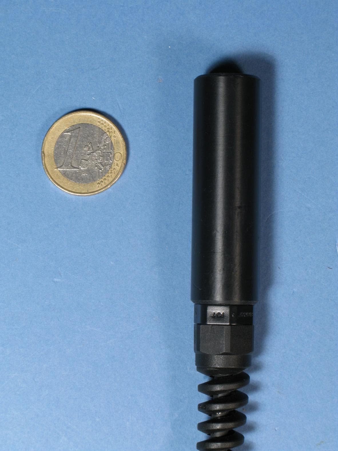
Click to zoom
Application Details
- Equipment Class
- DCD - Part 15 Low Power Transmitter Below 1705 kHz
- Date of Grant
- Sep 28, 2010
- Application Purpose
- Original Equipment
- Date of Application
- Sep 23, 2010
- Equipment Note
- Proximity RFID Module
- Frequency Range
- 0.12800000 - 0.12800000
- Company
- Dorset Identification b.v.
- Country
- Netherlands
Documents & Files
Document Text
Text extracted from the exhibit documents filed with the FCC. Open a document above to read the original.
Users Manual
USER MANUAL trovan LID665 stationary decoder READ THIS MANUAL FIRST! Date: August 2010 Copyrights: Dorset identification B.V. Tel. +31 543 477119 Fax +31 543 475355 Email : [email protected] www: http://www.dorset.nu The LID665 complies with FCC Rule Part 15 Operation is subject to the following two conditions: 1. this device may not cause interference and 2. this device must accept any interference, including interference that may cause undesired operation of the device User manual LID665 Dorset Identification b.v. Reserves the rights to change specifications without prior notice Federal Communications Commission notice This equipment has been tested and found to comply with the limits for a Class B digital device, pursuant to Part 15 of the FCC Rules These limits are designed to provide reasonable protection against harmful interference in a residential installation. This equipment generates, uses, and can radiate radio frequency energy, and if not installed and used in accordance with the instructions, may cause harmful interference to radio communications. However, there is no guarantee that interference will not occur in a particular installation If this equipment does cause harmful interference to radio or television reception, which can be determined by turning the equipment off and on, the user is encouraged to try and correct the interference by one or more of the following measures: • Reorient or relocate the receiving antenna. • Increase the distance between the equipment and the receiver. • Connect the equipment to an outlet on a circuit different from that to which the receiver is connected. • Consult the dealer or an experienced radio/TV technician for help. FCC Caution: Any changes or modifications not expressly approved by the party responsible for compliance could void the user’s authority to operate this equipment This device and its antenna(s) must not be co-located or operating in conjunction with any other antenna or transmitter. User manual LID665 Dorset Identification b.v. Reserves the rights to change specifications without prior notice 2 Contents: 1 ABOUT THE WINDOWS® PC PROGRAM. ....................................................................................................... 3 1.1 HOW TO INSTALL THE SOFTWARE? ............................................................................................................................. 3 1.2 START THE SOFTWARE ................................................................................................................................................. 3 2 THE SETTINGS TABSHEET. ................................................................................................................................... 4 2.1 READER SETTINGS. ...................................................................................................................................................... 4 2.2 BAUDRATE. ................................................................................................................................................................... 5 2.3 TRANSMIT OPTIONS. .................................................................................................................................................... 5 2.4 READ OPTIONS. ............................................................................................................................................................ 5 2.5 CHANGE UNIT NUMBER (RS485 ONLY) ..................................................................................................................... 7 2.6 CHANGE PASSWORD. ................................................................................................................................................... 7 3 THE HISTORY TABSHEET. ..................................................................................................................................... 8 4 THE DBASE TABSHEET. ......................................................................................................................................... 10 4.1 INDIVIDUAL CARD HOLDER INFORMATION................................................................................................................ 11 4.2. INFORMATION IN TABLE FORM ................................................................................................................................. 11 4.3 GOLD CARD................................................................................................................................................................. 11 4.4 SILVER CARD .............................................................................................................................................................. 11 5 ABOUT THE LID665V4.1 DECODER ................................................................................................................ 12 5.1 HOW TO CONNECT THE LID665V4.1 ...................................................................................................................... 13 5.2 LID665V14 BACKPLANE CONNECTIONS ................................................................................................................. 14 7 POWERSUPPLY LID650 & LID665: ................................................................................................................ 17 8 COMMUNICATIONS ................................................................................................................................................. 18 8.1 RS232 SERIAL COMMUNICATION ............................................................................................................................. 18 8.2 RS485 NETWORK COMMUNICATION ........................................................................................................................ 18 8.2.1 RS485 BUS GENERAL: ..............................................................................................................................…
Text truncated - open the document above for the full version.
Cover Letter(s)
FEDERAL COMMUNICATIONS COMMISSION DECLARATION OF CONFORMITY (DoC) Equipment: RFID decoder module Trademark(s) and Model(s): DORSET ID Manufacturer: Dorset Identification b.v. FCC ID in case other parts of this equipment are subject to certification: TLH8471302 This device complies with Part 15 of the FCC Rules. Operation is subject to the following two conditions: (1) this device may not cause harmful interference, and (2) this device must accept any interference received, including interference that may cause undesired operation. The following test reports are subject to this declaration: Test report number: 20103899300 Issue date: 10 August 2010 The following manufacturer/importer/entity (located in the USA) is responsible for this declaration: Company name: EID Ltd Name/Title (legal representative): Barbara P Masin Address: 1313 Danielson Road no. 11, CA 93108, Santa Barbara Phone: +1 805 565 1288 Fax: +1 805 565 1127 E-mail: [email protected] Date: August 11 th 2010 Signature: FCC
Cover Letter(s)
Request for non-disclosure RF_501_02 To:Telefication B.V. Attn: Dept. FCC TCB Edisonstraat 12A 6902 PK ZEVENAAR The Netherlands Subject: Request for non-disclosure (FCC ID:TLH 8471302) Reference number: 150610.RS.01 Date: June 15 th , 2010 Dear FCC TCB, Pursuant to 47 CFR Section 0.459(a) & (b), Dorset Identification B.V. hereby requests non-disclosure and confidential treatment of the following materials submitted in support of FCC certification application for FCC ID: (TLH 8471302) a.Schematic diagrams b.Operational description c.Bill of Material d.PCB layout Above materials contain secrets, proprietary and technical information, which would customarily be guarded from competitors under 47 CFR, section 0.457(d)(2). Disclosure or publication or any portion of this company confidential material to other parties could cause substantial competitive harm and provide unjustified benefits for competitors. Dorset Identification B.V. understands that pursuant to 47 CFR section 0.457(d)(1)(ii) disclosure of the applicant and all accompanying documentation will not be made before the date of the grant. Roland Stump Dorset Identification b.v.
Cover Letter(s)
RF_734_00, Issue 1 Modular Approval Request FCC (per DA 00-1407) FCC ID: ___ TLH8471302____ Items to be covered Answer from applicant 1. The modular transmitter must have its own RF shielding. Not applicable. 2. The modular transmitter must have buffered modulation/data inputs (if such inputs are provided) to ensure that the module will comply with Part 15 requirements under conditions of excessive data rates or over-modulation. Applicable, the modular transmitter has buffered modulation/data inputs. 3. The modular transmitter must have its own power supply regulation. Applicable, the modular transmitter has its own power supply regulation. 4. The modular transmitter must comply with the antenna requirements of Section 15.203 and 15.204(c). The antenna must either be permanently attached or employ a “unique” antenna coupler (at all connections between the module and the antenna, including the cable).. Applicable, the antenna is permantly attached to the modular transmitter. 5. The modular transmitter must be tested in a stand-alone configuration, i.e., the module must not be inside another device during testing. This is intended to demonstrate that the module is capable of complying with Part 15 emission limits regardless of the device into which it is eventually installed. Applicable, the modular transmitter has been tested when installed in two different types of unshielded host devices. 6. The modular transmitter must be labeled with its own FCC ID number, and, if the FCC ID is not visible when the module is installed inside another device, then the outside of the device into which the module is installed must also display a label referring to the enclosed module. This exterior label can use wording such as the following: “Contains Transmitter Module FCC ID: XYZMODEL1” or “Contains FCC ID: XYZMODEL1.” Any similar wording that expresses the same meaning may be used. The Grantee may either provide such a label, an example of which must be included in the application for equipment authorization, or, must provide adequate instructions along with the module which explain this requirement. In the latter case, a copy of these instructions must be included in the application for equipment authorization. Applicable, the modular transmitter is labeled with its own FCC ID number. An example of a label which must be attached to the outside of host devices is included in the application. 7. The modular transmitter must comply with any specific rule or operating requirements applicable to the transmitter and the manufacturer must provide adequate instructions along with the module to explain any such requirements. A copy of these instructions must be included in the application for equipment authorization. For example, there are very strict operational and timing requirements that must be met before a transmitter is authorized for operation under Section 15.231. For instance, data transmission is prohibited, except for operation under Section 15.231(e), in which case there are separate field strength level and timing requirements. Compliance with these requirements must be assured. Not applicable. 8. The modular transmitter must comply with any applicable RF exposure requirements. For example, FCC Rules in Sections 2.1091, 2.1093 and specific Sections of Part 15, including 15.319(i), 15.407(f), 15.253(f) and 15.255(g), require that Unlicensed PCS, UNII and millimeter wave devices perform routine environmental evaluation for RF Exposure to demonstrate compliance. In addition, spread spectrum transmitters operating under Section 15.247 are required to address RF Exposure compliance in accordance with Section 15.247(b)(4). Modular transmitters approved under other Sections of Part 15, when necessary, may also need to address certain RF Exposure concerns, typically by providing specific installation and operating instructions for users, installers and other interested parties to ensure compliance. Not applicable. Note: If compliance with one or more of the numbered requirements, listed above, cannot be demonstrated, it may be possible to obtain a “Limited Modular Approval” (LMA). Name and surname of applicant (or authorized representative): _R. Stump____________ Date: __August 11, 2010_ Signature: ___________________________
External Photos
Photographs module 20103899300 External PHOTOGRAPH 1: TOP VIEW............................................................................................................................... 2 PHOTOGRAPH 2: BOTTOM VIEW WITH LABEL LOCATION ..................................................................................... 3 PHOTOGRAPH 3: EXTERNAL ANTENNA TYPE ANT614 ......................................................................................... 4 PHOTOGRAPH 4: EXTERNAL ANTENNA TYPE ANT614OEM ................................................................................ 5 PHOTOGRAPH 5: EXTERNAL ANTENNA TYPE ANT613 ......................................................................................... 6 Page: 2 of 6 Report number:20103899300 Photograph 1: Top view Page: 3 of 6 Report number:20103899300 Photograph 2: Bottom view with label location Page: 4 of 6 Report number:20103899300 Photograph 3: external antenna type ANT614 Page: 5 of 6 Report number:20103899300 Photograph 4: external antenna type ANT614OEM Page: 6 of 6 Report number:20103899300 Photograph 5: external antenna type ANT613
ID Label/Location Info
Dorset Identification b.v. Weverij 26 NL-7122 MS Aalten +31 (0)543 477119 +31 (0)543 475355 [email protected] SN NUMBER ******* TYPE LID665 VERSION V*.** VOLTAGE 110VAC/60Hz Contains transmitter module FCC ID:TLH8471302
ID Label/Location Info
FCC ID: TLH8471302 Module label and location
Internal Photos
Photographs module 20103899300 Internal PHOTOGRAPH 1: INTERNAL VIEW...................................................................................................................... 2 PHOTOGRAPH 2: FRONT OF RADIO MODULE ...................................................................................................... 3 PHOTOGRAPH 3: BOTTOM OF RADIO MODULE ................................................................................................... 4 PHOTOGRAPH 4: VIEW ON CONNECTOR BOARD .................................................................................................. 5 Page: 2 of 5 Report number:20103899300 Photograph 1: internal view Page: 3 of 5 Report number:20103899300 Photograph 2: front of radio module Page: 4 of 5 Report number:20103899300 Photograph 3: bottom of radio module Page: 5 of 5 Report number:20103899300 Photograph 4: view on connector board
Test Report
Test report 20103899300 - Rev. 1.0 based on: FCC part 15B, section 15.107 and 15.109; part 15C, section 15.205, 15.207 and 15. 209 (10-01-09 edition) Proximity RFID Decoder DORSET ID LID665-MULTI Report number:20103899300 - Rev. 1.0 Contents MAIN MODULE .............................................................................................................................................. 3 1 INTRODUCTION ................................................................................................................................ 3 2 PRODUCT ............................................................................................................................................ 4 3 TEST SCHEDULE ............................................................................................................................... 4 4 PRODUCT DOCUMENTATION ........................................................................................................ 5 5 OBSERVATIONS AND COMMENTS ............................................................................................... 5 6 SUMMARY .......................................................................................................................................... 5 7 CONCLUSIONS ................................................................................................................................... 6 TEST RESULTS MODULE ............................................................................................................................ 7 1 SUMMARY .......................................................................................................................................... 7 2 EMISSION TESTS ............................................................................................................................... 8 2.1 Conducted Disturbance Measurement .......................................................................................... 8 2.2 Radiated Disturbance: Measurement (0.009 – 30 MHz) ............................................................ 10 2.3 Radiated Disturbance: Measurement (0.030 – 1 GHz) ............................................................... 13 USED TEST EQUIPMENT MODULE ........................................................................................................ 15 This report comprises of three modules. The total number of pages is: 17 Page: 3 of 17 Main module Report number: 20103899300 - Rev. 1.0 Main module 1 Introduction This report contains the result of tests performed by: Telefication B.V. Edisonstraat 12 a 6902 PK Zevenaar The Netherlands Telefication complies with the accreditation criteria for test laboratories as laid down in ISO/IEC 17025:2005. The accreditation covers the quality system of the laboratory as well as the specific activities as described in the authorized annex bearing the accreditation number L021 and is granted on 30 November 1990 by the Dutch Council For Accreditation (RvA: Raad voor Accreditatie). The contents of this test report, if reproduced, shall be copied in full, unless special consent in writing for reproduction in part is granted by Telefication. Copyright of this test report is reserved to Telefication. Ordering party: Company name : Dorset Identification b.v. Address : Weverij 26 Zipcode : 7122 MS City/town : Aalten Country : The Netherlands Date of order : 16 July 2010 Page: 4 of 17 Main module Report number: 20103899300 - Rev. 1.0 2 Product A sample of the following product was submitted for testing: Product name : Proximity RFID Decoder Manufacturer : Dorset Identification b.v. Trade mark : DORSET ID Type designation : LID665-MULTI FCC ID : TLH8471302 Emission designator : 128KN0N Hardware version : -- Software version : -- Serial number (host) : t5270001 3 Test schedule Tests are carried out in accordance with the specification detailed in chapter 6 "Summary" of this report. Tests are carried out at the following location: Telefication, Zevenaar (registered as an accredited test laboratory with designation number NL0001 under the US-EU MRA) The sample of the product was received on: 1 July 2010 Tests are carried out between: 19 July and 27 July 2010 Page: 5 of 17 Main module Report number: 20103899300 - Rev. 1.0 4 Product documentation For production of this report no product documentation has been used. 5 Observations and comments The product comes with three different antennas. They are type designated as ANT 613, ANT614 and ANT614OEM. The sample is intended to be used in the host type LID665. Combinations of host type LID665, the antennas ANT 613, ANT614 , ANT614OEM and the module LID665-MULTI may have the following type designations: LID665N, LID665A, LID665-MULTI, LID665-DT-USB and MUL/614W. Radiated emission tests of the transmitter portion of the 128 kHz transceiver are carried out with each antenna type. Radiated emission tests of the host are carried out with the antenna type ANT614 only. Radiated emissions of the receiver portion of the 128 kHz transceiver are exempt from complying with the technical provisions of FCC part 15 pursuant to section 15.101(b). 6 Summary The product is intended for use in the following application area: PART 15 LOW POWER TRANSMITTER BELOW 1705 kHz The sample is tested according to the following specifications: FCC part 15B, section 15.107 and 15.109; part 15C, section 15.205, 15.207 and 15. 209 (10-01-09 edition) Page: 6 of 17 Main module Report number: 20103899300 - Rev. 1.0 7 Conclusions The sample of the product showed NO NON-COMPLIANCES to the specifications stated in chapter 6 of this report. The results of the tests as stated in this report, are exclusively applicable to the product item as identified in this report. Telefication accepts no responsibility for any stated properties of product items in this test report, which are not supported by the tests as specified in section 6 “Summary”. All tests are performed by: name : ing. P.A. Suringa …
Text truncated - open the document above for the full version.
Test Setup Photos
Photographs module 20103899300 Test set up PHOTOGRAPH 1: TEST SET UP 0.009 - 30 MHZ (ANT613) ................................................................................. 2 PHOTOGRAPH 2: TEST SET UP 0.009 - 30 MHZ (ANT614OEM) ........................................................................ 3 PHOTOGRAPH 3: TEST SET UP 0.009 - 30 MHZ (ANT614) ................................................................................. 4 PHOTOGRAPH 4: TEST SET UP 0.03 - 1 GHZ (ANT613) ..................................................................................... 5 PHOTOGRAPH 5: TEST SET UP 0.03 - 1 GHZ (ANT614OEM)............................................................................. 6 PHOTOGRAPH 6: TEST SET UP 0.03 - 1 GHZ (ANT 614) .................................................................................... 7 PHOTOGRAPH 7: CONDUCTED EMISSIONS TEST TABLE ....................................................................................... 8 Page: 2 of 8 Report number:20103899300 Photograph 1: Test set up 0.009 - 30 MHz (ANT613) Page: 3 of 8 Report number:20103899300 Photograph 2: Test set up 0.009 - 30 MHz (ANT614OEM) Page: 4 of 8 Report number:20103899300 Photograph 3: Test set up 0.009 - 30 MHz (ANT614) Page: 5 of 8 Report number:20103899300 Photograph 4: Test set up 0.03 - 1 GHz (ANT613) Page: 6 of 8 Report number:20103899300 Photograph 5: Test set up 0.03 - 1 GHz (ANT614OEM) Page: 7 of 8 Report number:20103899300 Photograph 6: Test set up 0.03 - 1 GHz (ANT 614) Page: 8 of 8 Report number:20103899300 Photograph 7: Conducted emissions test table
Contact Information
Applicant
Roland Stump
Technical Contact
Dorset Identification b.v.Remco Nijenhuis
[email protected]+31 543 477119
Weverij 26 · Aalten · Netherlands
Test Firm
Kiwa Nederland B.V.Willem Jong
[email protected]+31 889983621
Technical Specifications
| # | Rule Parts | Frequency Range | Power Output |
|---|---|---|---|
| 1 | 15C | 0.128 MHz - 0.128 MHz | - |