TMPCS-600Wireless calling system (Happy Call)
Charmsori Electric Telecom Co., Ltd.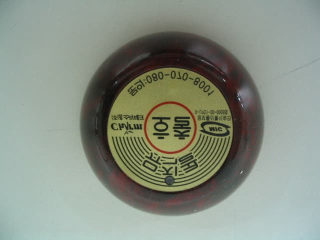
Click to zoom
Application Details
- Equipment Class
- DSC - Part 15 Security/Remote Control Transmitter
- Date of Grant
- Oct 13, 2005
- Application Purpose
- Original Equipment
- Date of Application
- Oct 13, 2005
- Equipment Note
- Wireless calling system (Happy Call)
- Frequency Range
- 311.00000000 - 311.00000000
- Country
- South Korea
Documents & Files
Document Text
Text extracted from the exhibit documents filed with the FCC. Open a document above to read the original.
Users Manual
Page 1 of 9 User’s Guide of the Happy Call Any changes or modifications to the equipment not expressly approved by the party responsible for compliance could void user’s authority to operate the equipment. This device complies with part 15 of the FCC Rules. Operation is subject to the following two conditions: (1) This device may not cause harmful interference, and (2) This device must accept any interference received, including interference that may cause undesired operation. CHARMSORI Electric Telecom Co., Ltd. Page 2 of 9 1. Product Description Thanks for purchasing Happy Call System. This device is wireless calling system which adopted High-performance CPU(Central Processing Unit) of Pro-Chips Company. Using Wireless Transmitter and Receiver, User can communicate each other without talking by face to pace, so this device is very useful at restaurants. 2. Product Details 1) Receivers - Front View - Rear View Page 3 of 9 2) Transmitter ** Repeator and Adaper is optional. 3. Operation Instruction 1)Receiver MC-6000 Series - When power is on, the receiver conduct self-diagnosis with music is being played and the display blinking in order. - When a table number is input, it appears on the screen and the number goes off after time setup. - Input numbers can be memorized(maximum 10) and replayed. Page 4 of 9 MC-7000 Series - When power is on, the receiver conducts self-diagnosis with music is being played and the display blinking in order. - When a table number is input, it appears on the screen and the number goes off after time setup. - When several numbers are input, they appear moving from the left to the right in the order of input. 2) Transmitter (commonly used in MC-6000 & 7000 Series) 3) Repeator (commonly used in MC-6000 & 7000 Series) 4. Installation 1) Receiver Avoid humid places. Install it at least 3m away from wireless devices(such as wireless phones) and the places of big magnetism(such as speakers). Check the electric power source and voltage of the place where it is installed(220V). The antenna is regulated at the angle ranges of 0°~45° and a 3-stage antenna is used. When power is on, check the self-diagnosis(refer to 1-3). 2) Transmitter Install it at least 3m away from the receiver. In case batteries(A23, 12V) are exchanged, insert identical batteries after loosening screws of the backside(pay attention to +,-). Batteries should be exchanged when the blinking of the lamp on the top of the transmitter conspicuously slows down. Page 5 of 9 3) Repeator (In case of installation) The translator, as a wireless one, can be installed by the only power connection without additional electric wire. The channel choice of the translator is the same as the channel regulation of the backside receiver(SW1, SW2 and SW3 are turned on always). The translator should be installed in places near the regions where transmission is not available. Page 6 of 9 5. Option set-up Page 7 of 9 Page 8 of 9 6. Check-point when abnormal operation Page 9 of 9 7. Specification 1. Power : Max 1.2 W, Normal 0.8 W 2. Input Voltage of Receiver : AC220V, 60 Hz / DC 12V 850 mA ~ 1 A 3. Channel number displayed : 128 4. Channel Quantity : 32 5. Temperture : -10 6. Transmitter power : DC 12V 33 mA (Alkaline Battery)
External Photos
10. Attachment B – Photos of the EUT Top View of EUT Bottom View of EUT
ID Label/Location Info
FCC ID LABEL 1. FCC ID label drawing 2. FCC ID label location CHARMSORI Electric Telecom Co., Ltd. Model : CS-600 FCC ID : TMPCS-600 Made in Korea This device complies with part 15 of the FCC rules. Operation is subject to the following two conditions: (1)This devices may not cause harmful interference, and (2)This device must accept any interference received, including interference that may cause undesired operation.
Internal Photos
Top View of PCB View of PCB
Operational Description
1. Operation description (Model : CS-600) 1) ENCODE_MDT75C271_IC: the U1 is a “32BIT_4BIT control ENCODE_IC” and has a function to output 400 Hz of ASK serial data which is decided by SW1. 2) High-frequency oscillation section: the Q1 is a “transformed colpitts oscillating circuit”, and Q1 is oscillated with resonating to the unique frequency (311.0625 MHz) of X1 Saw Resonator. The high frequency signal from Q1’s collector port is weak, so this signal is amplified by Q2, then the signal radiated from the antenna to the air. 3) The C3 is Q1's bias condenser, when “the serial data signal from the ENCODE_IC controller” is +(plus) direction, then the Q1 oscillates. When “the serial data signal from the ENCODE_IC controller” is -(minus) direction, then the Q1 stops oscillation. 4) Thus According to the “Serial data signal polarity(+, -)” Q1 repeats oscillation and non- oscillation, naturally we call that Q1 has a ASK modulation function. 5) The L2 is a Current-limit Coil which limits the current of Q1's collector port, L2 act to eliminates noise and spurious. 6) The C3 acts to bypass “the high frequency noise which current on VCC line” to the Ground.
Test Report
VERIFICATION OF COMPLIANCE Charmsori Electric Telecom Co., Ltd. Call Service Happy Call CS-600 STROR-05-043 Oct. 04, 2005 ~ Oct. 11, 2005 APPLICABLE STANDARDS 1. General Description of EUT “ ” 2. General Information of EUT 3. Test Procedure 3.1 Conducted Emission 3.2 Radiated Emission 4. Test Condition 4.1 Test Configuration 4.2 EUT Operation 4.3 Peripherals / Support Equipment Used 5. Field Strength of Fundamental FCC Part 15, Subpart C, Section 15.231 (b) Test Equipment Used EQUIPMENT MANUFACTURER MODEL CAL DUE. Test Receiver Rohde & Schwarz ESIB 26 Mar. 2006 Log-periodic Rohde & Schwarz UHALP9107 Jan. 2006 6. Spurious Emission FCC Part 15, Subpart C, Section 15.231 (b) Test Equipment Used EQUIPMENT MANUFACTURER MODEL CAL DUE. Test Receiver Rohde & Schwarz ESIB 26 Mar. 2006 Log-periodic Antenna Rohde & Schwarz UHALP9107 Jan. 2006 Horn Antenna Schwarzbeck BBHA9120D(0600) Jul. 2006 7. Bandwidth of Operation Frequency FCC Part 15, Subpart C, Section 15.231(c) A UnitdB Ê V Ref Lvl 65 dB Ê V Ref Lvl 65 dB Ê V RF Att 10 dB Center310.8533487 MHzSpan100 kHz10 kHz/ RBW 1 kHz VBW 1 kHz SWT 250 ms IN1 1VIEW1MA -30 -20 -10 0 10 20 30 40 50 60 -35 65 1 1 2 Delta 2 [T1] 0.63 dB 7.41482966 kHz 1 [T1] 23.24 dB Ê V 310.85244689 MHz 2 [T1] 0.63 dB 7.41482966 kHz 1 [T1] 21.02 dB 3.60721443 kHz D1 23.3 dB Ê V Date: 10.OCT.2005 10:10:04 Test Equipment Used EQUIPMENT MANUFACTURER MODEL CAL DUE. Test Receiver Rohde & Schwarz ESIB 26 Mar. 2006 Log-periodic Antenna Rohde & Schwarz UHALP9107 Jan. 2006 8. Transmission Time FCC Part 15, Subpart C, Section 15.231(a) (1) A UnitdB Ê V Ref Lvl 95 dB Ê V Ref Lvl 95 dB Ê V RF Att 10 dB RBW 200 kHz VBW 200 kHz IN1 1MA SWT 5 s Center 311.1138697 MHz500 ms/ 1MAX1MA 0 10 20 30 40 50 60 70 80 90 -5 95 1 2 Delta 2 [T1] 22.31 dB 511.022044 ms Date: 10.OCT.2005 09:54:45 Test Equipment Used EQUIPMENT MANUFACTURER MODEL CAL DUE. Test Receiver Rohde & Schwarz ESVS 10 Jun. 2006 Log-periodic Antenna Rohde & Schwarz UHALP9107 Jan. 2006 9. Attachment A – Photo of test set up
Test Setup Photos
9. Attachment A – Photo of test set up
Contact Information
Applicant
Jaedong Kim(Managing Director)
Test Firm
SGS Korea Co., Ltd.Julia Choi
Technical Specifications
| # | Rule Parts | Frequency Range | Power Output |
|---|---|---|---|
| 1 | 15.231 | 311 MHz - 311 MHz | - |