TP5433TX4Handheld Transmitter
MHOUSE SRL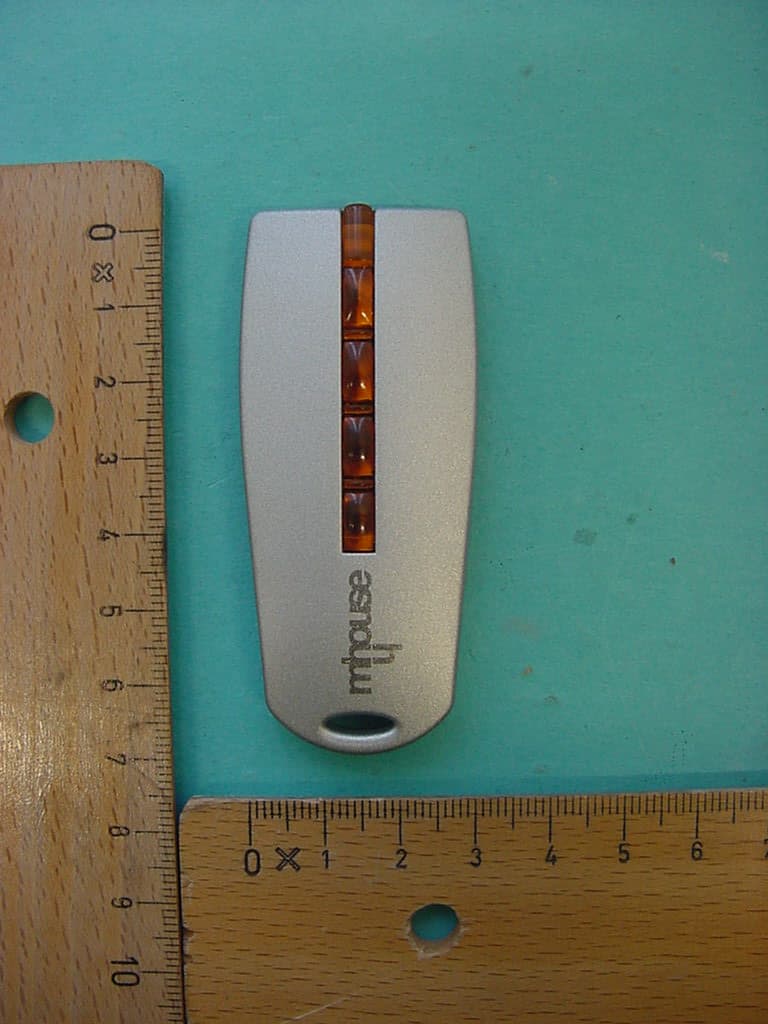
Click to zoom
Application Details
- Equipment Class
- DSC - Part 15 Security/Remote Control Transmitter
- Date of Grant
- Nov 29, 2005
- Application Purpose
- Original Equipment
- Date of Application
- Nov 29, 2005
- Equipment Note
- Handheld Transmitter
- Frequency Range
- 433.92000000 - 433.92000000
- Company
- MHOUSE SRL
- Country
- Italy
Documents & Files
Document Text
Text extracted from the exhibit documents filed with the FCC. Open a document above to read the original.
Users Manual
This device complies with Part 15 of the FCC Rules and with RSS-210 of Industry Canada. Operation is subject to the following two conditions: (1) this device my not cause harmful interference, and (2) this device must accept any interference received, including interference that may cause undesired operation. Warning: Changes or modifications made to this equipment not expressly approved by MHOUSE s.r.l. may void the FCC authorization to operate this equipment. This equipment has been tested and found to comply with the limits for a Class B digital device, pursuant to Part 15 of the FCC Rules. These limits are designed to provide reasonable protection against harmful interference in a residential installation. This equipment generates, uses and can radiate radio frequency energy and, if not installed and used in accordance with the instructions, may cause harmful interference to radio communications. However, there is no guarantee that interference will not occur in a particular installation. If this equipment does cause harmful interference to radio or television reception, which can be determined by turning the equipment off and on, the user is encouraged to try to correct the interference by one or more of the following measures: • Reorient or relocate the receiving antenna. • Increase the separation between the equipment and receiver. • Connect the equipment into an outlet on a circuit different from that to which the receiver is connected. • Consult the dealer or an experienced radio/TV technician for help. IST173 4851 rev.000
Users Manual
Installation instructions and warnings English IST WG20-GB 4865 Rev. 01 del 08-04-2005 MhouseKit WG20 For the automation of swing gates. 2 WG20 Instructions Information Contents 1 Warnings3 2 Product description4 2.1 Applications4 2.2 Description of the automation4 2.3 Description of Devices5 2.3.1 WG10 Electromechanical Gearmotors5 2.3.2 Release keys5 2.3.3 CL20 Control Unit6 2.3.4 PH1 Photocells6 2.3.5 KS1 Key-Operated Selector Switch6 2.3.6 FL1 Flashing Light with Incorporated Aerial6 2.3.7 TX4 Radio Transmitters6 3 Installation7 3.1 Preliminary checks7 3.1.1 Operating Limits8 3.1.2 Tools and Materials8 3.1.3 List of Cables8 3.2 Preparing the Electrical System9 3.2.1 Connection to the Electrical Mains9 3.3 Installation of the Various Devices9 3.3.1 WG10 gearmotor mounting9 3.3.2 Photocells11 3.3.3 KS1 Key-Operated Selector Switch12 3.3.4 FLI Flashing Light12 3.3.5 CL20 Control Unit13 3.4 Power Supply Connection15 3.5 Initial checks15 3.5.1 Recognition of Connected Devices15 3.5.2 Recognition of Gate Leaves' Opening and Closing Angles16 3.5.3 Checking the Radio Transmitters16 3.6 Regulations16 3.6.1 Selecting the Speed of the Leaf16 3.6.2 Selecting the Type of Operating Cycle17 3.7 Testing and commissioning17 3.7.1 Testing17 3.7.2 Commissioning17 4 Maintenance18 4.1 Dismantling and Disposal18 5 Additional information19 5.1 Advanced Adjustments19 5.1.1 Adjusting the Parameters with the Radio Transmitter19 5.1.2 Checking the Adjustments with the Radio Transmitter20 5.2 Optional Accessories20 5.3 Adding or Removing Devices20 5.3.1 ECSBus20 5.3.2 STOP Input20 5.3.3 Recognition of Other Devices21 5.3.4 Addition of Optional Photocells21 5.4 Memorization of Radio Transmitters22 5.4.1 Memorization Mode 122 5.4.2 Memorization Mode 222 5.4.3 "Remote" Memorization22 5.4.4 Deleting a Radio Transmitter 23 5.4.5 Deleting all the Radio Transmitters23 5.5 Troubleshooting23 5.6 Diagnostics and Signals24 5.6.1 Photocells24 5.6.2 Flashing light24 5.6.3 Control Unit25 6 Technical characteristics26 7 Annexes28 7.1 Annexe 1: CE Declaration of Conformity of WG20 Components 29 7.2 Annexe 2: CE Declaration of Conformity of Power Operated Gate 31 7.3 Annexe 3: Operating Guide 33 7.3.1 Safety regulations33 7.3.2 Gate Control33 7.3.3 Maintenance Operations to Be Performed by the User34 7.3.4 Replacing the Remote Control Battery34 This manual may be reproduced provided no part of it is omitted or modified. No part of this manual may be translated into other languages without the prior authorization and subsequent examination by MHOUSE MHOUSE disclaims all responsibility for damage resulting from improper use of its products. You are therefore invited to read this manual carefully. MHOUSE, in order to improve its products, reserves the right to modify them at any time without prior notice. In any case, the manufacturer guarantees their functionality and fitness for the intended purposes. For any information please contact: MHOUSE S.r.l. via Pezza Alta, 13, Z.I. 31046 Oderzo Tel: 0422 202109 Fax: 0422 852582 email: [email protected] http: www.mhouse.biz. WG20 is produced by NICE S.p.a. (TV) I, MHOUSE S.r.l. is an affiliate of the Nice S.p.a group. WG20 Instructions 3 • If this is the first time that you install a WG20 gate automation system we recommend that you dedicate some of your time to reading this man- ual. You should read it before you start installing the system, so you don't have to rush to finish the work. Keep all the components of the WG20 system handy so that you can read, check and verify all the information contained in this manual. How- ever, do not carry out the adjustment and memorization stages other- wise, during the actual installation of the products, you will have to deal with settings that differ from the original factory ones. • When reading this manual, pay special attention to the sections marked by the following symbol: these sections are particularly important for safety. • Store this manual safely for future use. • This manual, as well as the design and manufacture of the devices that make up WG20, comply fully with the standards and regulations in force. • Considering the hazards that may exist during the installation and operation of WG20, it is necessary that also the installation be carried out in strict compliance with current legislation, standards and regulations, particularly: • This manual contains important information regarding personal safety; before you start installing the components, it is important that you read and understand all the information contained here- in. Do not proceed with the installation if you have doubts of any sort; if necessary, refer to the MHOUSE customer service depart- ment for clarifications. • Before you start with the installation, make sure that each sin- gle WG20 device is suitable for the intended automation purpos- es; pay special attention to the data provided in chapter 6 "Tech- nical Characteristics". If even a single device is not suitable for the intended application, do not proceed with the installation. • Before you start with the installation, check whether additional devices or materials are needed to complete the automation with WG20 based on the specific application requirements. • The WG20 automation system must not be used until the automation has been commissioned as described in paragraph 3.7.2 "Commissioning". • The WG20 automation system cannot be considered as a suit- able intrusion protection system. If you require efficient protec- tion you need to integrate WG20 with other devices. • The packing materials for WG20 must be disposed of in com- pliance with local regulations. • Do not make modifications to any components unless provided for in this manual. This type of operations will only cause mal- functions. MHOUSE disclaims any liability for damage resulting from modified products. • Do not immerse the automation parts in water or any other liq- uid. During installation, ensure that water does not leak into the control u…
Text truncated - open the document above for the full version.
Cover Letter(s)
N N i i c c e e S S p p A A V V i i a a P P e e z z z z a a A A l l t t a a , , 1 1 3 3 Z Z . . I I . . R R u u s s t t i i g g n n è è I I - - 3 3 1 1 0 0 4 4 6 6 O O d d e e r r z z o o T T V V I I t t a a l l i i a a P P h h o o n n e e + + 3 3 9 9 . . 0 0 4 4 2 2 2 2 . . 8 8 5 5 3 3 8 8 3 3 8 8 F F a a x x + + 3 3 9 9 . . 0 0 4 4 2 2 2 2 . . 8 8 5 5 3 3 5 5 8 8 5 5 P P . . I I V V A A 0 0 3 3 0 0 9 9 9 9 3 3 6 6 0 0 2 2 6 6 9 9 i i n n f f o o @ @ n n i i c c e e f f o o r r y y o o u u . . c c o o m m w w w w w w . . n n i i c c e e f f o o r r y y o o u u . . c c o o m m CONFIDENTIALITY REQUEST Federal Communication Commission Equipment Authorization Division, Application Processing Branch 7435 Oakland Mills Road Columbia, MD 21048 DATE 14/09/2005 TO WHOM IT MAY CONCERN Pursuant to Paragraphs §0.457 and 0.459 of the Commission’s Rules (47 C.F.R.) and Section §552(b)(4) of the Freedom of Information Act, Company requests confidentiality for the following products: FCC ID Number Product Title/Model PML 433TX4 TX4/U For the product stated above, we request that the following information be held confidential: 1. Circuit diagrams, BOM, and PCBs submitted as Equipment Authorization Electronic Filing attachment: "schematics”. 2. Block diagram submitted as Equipment Authorization Electronic Filing attachment: “blockdiagram”. 3. Operational description submitted as Equipment Authorization Electronic Filing attachment: “operational description” The above exhibits contain Company trade secrets and proprietary information that could be of benefit to our competitors regarding the design of our mobile handset. This material is not customarily available to the general public and we request that it be withheld from public inspection. If you have any questions, please feel free to contact me at the address shown below. Sincerely, Name: Oscar Marchetto Company: Nice S.p.A. Address: Via Pezza Alta, 13 Z.I. Rustignè I-31046 Oderzo (TV) Phone: +39.0422853838 Email: [email protected]
External Photos
CETECOM ICT Services GmbH Untertürkheimer Str. 6-10, 66117 Saarbruecken Phone: +49 (0) 681 598-0 Fax: -9075 RSC-Laboratory Phone: +49 (0) 681 598-0 Fax: -9075 Test report no.: 2-4088-01-02/05 Date: 2005-10-18 Page 23 of 26 6 Annex C: External Photographs of the Equipment Photo 1: CETECOM ICT Services GmbH Untertürkheimer Str. 6-10, 66117 Saarbruecken Phone: +49 (0) 681 598-0 Fax: -9075 RSC-Laboratory Phone: +49 (0) 681 598-0 Fax: -9075 Test report no.: 2-4088-01-02/05 Date: 2005-10-18 Page 24 of 26 Photo 2:
ID Label/Location Info
MHOUSE SRL Label & Labelling Size: 28x23mm R2mm Colour: White Material: PVC
Internal Photos
CETECOM ICT Services GmbH Untertürkheimer Str. 6-10, 66117 Saarbruecken Phone: +49 (0) 681 598-0 Fax: -9075 RSC-Laboratory Phone: +49 (0) 681 598-0 Fax: -9075 Test report no.: 2-4088-01-02/05 Date: 2005-10-18 Page 25 of 26 7 Annex D: INTERNAL PHOTOGRAPHS OF THE EQUIPMENT Photo 3: CETECOM ICT Services GmbH Untertürkheimer Str. 6-10, 66117 Saarbruecken Phone: +49 (0) 681 598-0 Fax: -9075 RSC-Laboratory Phone: +49 (0) 681 598-0 Fax: -9075 Test report no.: 2-4088-01-02/05 Date: 2005-10-18 Page 26 of 26 Photo 4:
Test Report
CETECOM ICT Services GmbH Untertürkheimer Str. 6-10, 66117 Saarbruecken Phone: +49 (0) 681 598-0 Fax: -9075 RSC-Laboratory Phone: +49 (0) 681 598-0 Fax: -9075 Test report no.: 2-4088-01-02/05 Date: 2005-10-18 Page 1 of 26 Recognized by the Federal Communications Commission Anechoic chamber registration no.: 90462 (FCC) Anechoic chamber registration no.: 3463 (IC) TCB ID: DE 0001 Accredited by the German Accreditation Council DAR–Registration Number DAT–P–176/94-D1 Independent ETSI compliance test house ETSI Accredited Bluetooth ® Test Facility (BQTF) Test report no. : 2-4088-01-02/05 Applicant : MHOUSE SRL Type : TX4/U Test Standard : FCC Part 15 / RSS210 FCC ID : TP5433TX4 Certification No. IC : 6156A-433TX4 CETECOM ICT Services GmbH Untertürkheimer Str. 6-10, 66117 Saarbruecken Phone: +49 (0) 681 598-0 Fax: -9075 RSC-Laboratory Phone: +49 (0) 681 598-0 Fax: -9075 Test report no.: 2-4088-01-02/05 Date: 2005-10-18 Page 2 of 26 Table of contents 1 GENERAL INFORMATION ................................................................................................................................... 3 1.1. ADMINISTRATIVE DATA OF THE TEST FACILITY..................................................................................................... 3 1.1.1 Identification of the testing laboratory ......................................................................................................... 3 1.2. NOTES................................................................................................................................................................... 3 1.3 DETAILS OF APPLICANT......................................................................................................................................... 4 1.4 APPLICATION DETAILS.......................................................................................................................................... 4 1.5 TEST ITEM............................................................................................................................................................. 5 1.6 TEST SETUP........................................................................................................................................................... 6 1.7 TEST SPECIFICATIONS............................................................................................................................................ 6 2 STATEMENT OF COMPLIANCE .......................................................................................................................... 7 2.1 SUMMARY OF MEASUREMENT RESULTS................................................................................................................ 7 2.1.1 CFR 47 Part 15 Radio frequency devices ..................................................................................................... 7 3 MEASUREMENTS AND RESULTS ....................................................................................................................... 8 4 FCC PART 15 SUBPART C...................................................................................................................................... 9 4.1 Timing of the transmitter .................................................................................................................................. 9 4.2 Field strength of the fundamental ................................................................................................................... 12 4.3 Field strength of the harmonics and the spurious........................................................................................... 13 4.4 Plots of measurements .................................................................................................................................... 14 4.5 Bandwidth of emission .................................................................................................................................... 16 5 ANNEX B: PHOTOGRAPHS OF TEST SITE ..................................................................................................... 21 6 ANNEX C: EXTERNAL PHOTOGRAPHS OF THE EQUIPMENT ................................................................ 23 7 ANNEX D: INTERNAL PHOTOGRAPHS OF THE EQUIPMENT.................................................................. 25 CETECOM ICT Services GmbH Untertürkheimer Str. 6-10, 66117 Saarbruecken Phone: +49 (0) 681 598-0 Fax: -9075 RSC-Laboratory Phone: +49 (0) 681 598-0 Fax: -9075 Test report no.: 2-4088-01-02/05 Date: 2005-10-18 Page 3 of 26 1 General information 1.1. Administrative data of the test facility 1.1.1 Identification of the testing laboratory Company name: Cetecom ICT Services GmbH Address: Untertürkheimerstr. 6-10 D-66117 Saarbruecken Germany Laboratory accreditation: DAR-Registration No. DAT-P-176/94-D1 Bluetooth Qualification Test Facility (BQTF) Federal Communications Commission (FCC) Identification/Registration No : 90462 Responsible for testing laboratory: Michael Berg Phone: +49 681 598 0 Fax: +49 681 598 9075 email: [email protected] 1.2. Notes The test results of this test report relate exclusively to the test item specified in 1.5. The CETECOM ICT Services GmbH does not assume responsibility for any conclusions and generalizations drawn from the test results with regard to other specimens or samples of the type of the equipment represented by the test item. The test report may only be reproduced or published in full. Reproduction or publication of extracts from the report requires the prior written approval of the CETECOM ICT Services GmbH. ..................................................... / .......................................................... Responsible for testing laboratory (Michael Berg / Dirk Hausknecht) ...................................................... / .......................................................... Responsible for test report (Michael Berg / Dirk Hausknecht) CETECOM ICT Serv…
Text truncated - open the document above for the full version.
Test Setup Photos
CETECOM ICT Services GmbH Untertürkheimer Str. 6-10, 66117 Saarbruecken Phone: +49 (0) 681 598-0 Fax: -9075 RSC-Laboratory Phone: +49 (0) 681 598-0 Fax: -9075 Test report no.: 2-4088-01-02/05 Date: 2005-10-18 Page 21 of 26 5 Annex B: Photographs of Test site Photo 1 (Radiated Emissions): CETECOM ICT Services GmbH Untertürkheimer Str. 6-10, 66117 Saarbruecken Phone: +49 (0) 681 598-0 Fax: -9075 RSC-Laboratory Phone: +49 (0) 681 598-0 Fax: -9075 Test report no.: 2-4088-01-02/05 Date: 2005-10-18 Page 22 of 26 Photo 2 (Radiated Emissions):
Contact Information
Applicant
Lauro Buoro
Test Firm
cetecom advanced GmbHGerald Schmidt
Technical Specifications
| # | Rule Parts | Frequency Range | Power Output |
|---|---|---|---|
| 1 | 15.231 | 433.92 MHz - 433.92 MHz | - |