FCCID.CO- FCC ID Database
HomeCompaniesEquipment ClassesSearch

© 2026 FCC ID Database. All rights reserved.

AboutContactData sourced from FCC public records
  1. Home/
  2. Dimplex North America LTD/
  3. TP7300032

TP7300032Remote Controller

Dimplex North America LTD
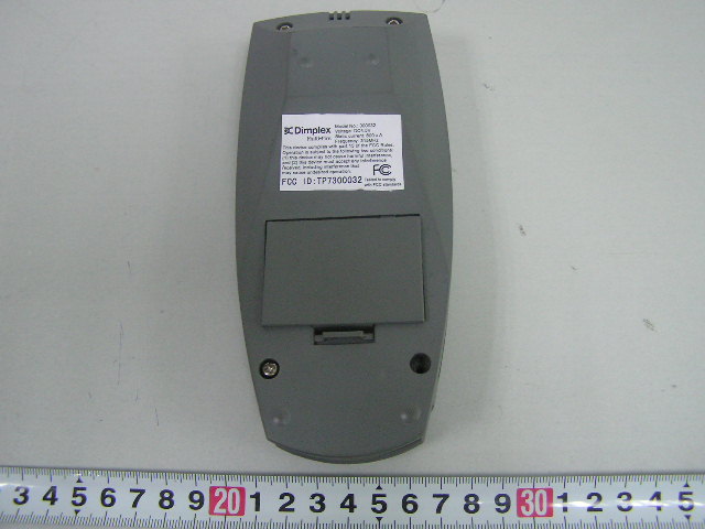
Remote Controller - FCC ID TP7300032 - Dimplex North America LTD
Click to zoom

Application Details

Equipment Class
DXX - Part 15 Low Power Communication Device Transmitter
Date of Grant
Nov 13, 2005
Application Purpose
Original Equipment
Date of Application
Nov 13, 2005
Equipment Note
Remote Controller
Frequency Range
315.00000000 - 315.00000000
Company
Dimplex North America LTD
Country
Canada

Documents & Files

Select a file to view

Users Manual

↗

Cover Letter(s)

↗

External Photos

↗

ID Label/Location Info

↗
↗

Internal Photos

↗

Test Report

↗

Test Setup Photos

↗

Document Text

Text extracted from the exhibit documents filed with the FCC. Open a document above to read the original.

Users Manual

FEDERAL COMMUNICATIONS COMMISSION INTERFERENCE STATEMENT This equipment has been tested and found to comply with the limits for a Class B digital device, pursuant to Part 15 of the FCC Rules. These limits are designed to provide reasonable protection against harmful interference in a residential installation. This equipment generates, uses and can radiate radio frequency energy and, if not installed and used in accordance with the instructions, may cause harmful interference to radio communications. However, there is no guarantee that interference will not occur in a particular installation. If this equipment does cause harmful interference to radio or television reception, which can be determined by turning the equipment off and on, the user is encouraged to try to correct the interference by one or more of the following measures: -- Reorient or relocate the receiving antenna. -- Increase the separation between the equipment and receiver. -- Connect the equipment into an outlet on a circuit different from that to which the receiver is connected. -- Consult the dealer or an experienced radio/TV technician for help. CAUTION: Any changes or modifications not expressly approved by the grantee of this device could void the user's authority to operate the equipment. Remote display Up button Left Button Flame ON/OFF button FLAME ON/OFF BUTTON Press the Flame On/Off button to turn the flame ON. HEATER ON/OFF BUTTON Press the Heater On/Off button to turn the heater NOTE A red indicator light will illuminate on the fireplace to indicate that the heater is ON. NOTE When the flame and/or the heater are ON, the unit will turn OFF when both control buttons are pressed at the same time. SLEEP TIMER 1. Set the sleep timer to the length of time you want the unit to operate by pressing the sleep timer button. NOTE The sleep timer can be set from 30 minutes to 8 hours. 2. Pressing the sleep timer button repeatedly will increase the sleep timer by 30 minute increments. 3. Press the flame button and/or the heater button to turn the unit ON. 4. The fireplace will automatically turn OFF when the sleep timer reaches 0 minutes. 5. The sleep timer can be reset by pressing the sleep timer button repeatedly until the sleep timer display disappears and the room temperature display is shown. SET CLOCK 1. Press the ENTER button until the middle display flashes. 2. Use the direction buttons on the hand held remote to move the cursor to the clock and press the ENTER button. 3. A day of the week will flash. 4. Use the left or right button to set the day of the week. Right button Down button Sleep timer button Heater ON/OFF button Enter button Occupancy Sensor Set temperature Day of week Room temperature Time of day Ambient Light Sensor Batteries 5. Press the up button and the hour display will flash. 6. Use the left or right button to set the hour. 7. Press the up button and the minute display will flash. 8. Use the left or right button to set the minute. 9. Press ENTER to return to the main menu. SET °F OR °C 1. Press the ENTER button until the middle display flashes. 2. Use the direction buttons on the hand held remote to move the cursor to and press ENTER. 3. Use the left or right button to toggle between °F and °C. 4. Press ENTER to select °F or °C. FLICKERING FIRELIGHT 1. Press the flame button to turn the flame ON. 2. Press the ENTER button until the middle display flashes. 3. Use the direction buttons on the hand held remote to move the cursor to and press ENTER. 4. Press the up button to turn the flickering top lights ON. 5. Press ENTER to return to the main menu. NOTE To turn the flickering lights OFF repeat steps 1 to 3 and then press the down button. FLAME SPEED 1. Press the flame button to turn the flame ON. 2. Press the ENTER button until the middle display flashes. 3. Use the direction buttons on the hand held remote to move the cursor to and press ENTER. 4. Repeatedly press the left or right arrow keys to change the flame speed. NOTE The bar graph located on the top of the screen displays the speed range of the flame motor. 5. Press ENTER to return to the main menu. LIGHT DIMMER 1. Press the flame button to turn the flame ON. 2. Press the ENTER button until the middle display flashes. 3. Use the direction buttons on the hand held remote to move the cursor to and press ENTER. 4. Repeatedly press the left or right arrow keys to change the brightness of the upper lights. NOTE The bar graph located on the top of the screen displays the upper light brightness range. AMBIENT LIGHT SENSOR When the room gets darker the upper lights dim allowing for a more intense and realistic flame effect. 1. Press the flame button to turn the flame ON. 2. Press the ENTER button until the middle display flashes. 3. Use the direction buttons on the hand held remote to move the cursor to and press ENTER. 4. Press the up button to turn the ambient light sensor ON. 5. Press ENTER to return to the main menu. NOTE To turn the ambient light sensor OFF repeat steps 1 to 3 and then press the down button. SLOW START/FADING EMBERS If the slow start function is being used at start up then the fading embers function will automatically be programmed at shut down. 1. Press the ENTER button until the middle display flashes. 2. Use the direction buttons on the hand held remote to move the cursor to and press ENTER. 3. Press the left or right button to select 1, 5, or 10 minutes. NOTE When the timer is set to 1, 5, or 10 minutes it determines the length of time over which the embers will fade upon turning the unit OFF. NOTE The slow start function timer is automatically programmed for 1 minute. This timer setting cannot be changed. 4. Press the up button to turn the slow start/fading embers function ON. 5. Press ENTER to return to the main menu. 6. Press the flame on/off button to activate slow start. NOTE When turning the unit OFF and the slow start/fading ember function is ON, the slow start/fading ember indicator will flash. OCCUPANCY SENSOR T…

Text truncated - open the document above for the full version.

Cover Letter(s)

FCC Confidential Authorization 2005-9-20 FEDERAL COMMUNICATIONS COMMISSIONS Authorization and Evaluation Division 7435 Oakland Mills Road Columbia, MD 21046 Confidentiality Request regarding application for certification of FCC ID: TP7300032. Pursuant to Sections 0.457 and 0.459 of the Commission’s Rules, we hereby request confidential treatment of information accompanying this application as outlined below: (1Technical information or operation description (2Description of the circuit functions (3Equipment specification (4Block diagram (5 Schematic diagram (6Bill of material (7PCB layout The above materials contain trade secrets and proprietary information not customarily released to the public. The public disclosure of these materials may be harmful to the applicant and provide unjustified benefits to its competitors. The applicant understands that pursuant to Section 0.457 of the Rules, disclosure of this application and all accompanying documentation will not be made before the date of the Grant for this application. Sincerely Yours, Mars huo Purchasing Manager Dimplex North America LTD Dimplex North America LTD

External Photos

External Photos EUT Front View EUT Rear View

ID Label/Location Info

ID Label Label

Internal Photos

Internal Photos EUT – Inside View EUT – All Module Front View EUT – All Module Rear View EUT – Main PCB Front View EUT – Main PCB Rear View EUT – LCD Module Front View EUT – LCD Module Rear View

Test Report

Note: The test report is specially limited to the above company and this particular sample only. It may not be duplicated without prior written consent of Bay Area Compliance Lab Corp. (ShenZhen). This report must not be used by the client to claim product certification, approval, or endorsement by NVLAP, NIST or any agency of the US Government. FCC PART 15.231 EMI MEASUREMENT AND TEST REPORT For Dimplex North America LTD 1367 Industrial Road Cambridge ON N1R 7G8 CANADA FCC ID: TP7300032 November 1, 2005 This Report Concerns: Original Report Equipment Type: Remote Controller Test Engineer: Merry Zhao Report No.: TSC05092801 Test Date: September 30-October 31, 2005 Reviewed By: Chris Zeng Prepared By: Bay Area Compliance Lab Corp. (ShenZhen) 6/F, the 3rd Phase of WanLi Industrial Building, ShiHua Road, FuTian Free Trade Zone, ShenZhen, Guangdong 518038, P.R.China Tel: +86-755-33320018 Fax: +86-755-33320008 Dimplex North America LTD. FCC ID: TP7300032 Report # TSC05092801 New Page 2 of 18 FCC Part 15.231 Test Report TABLE OF CONTENTS GENERAL INFORMATION.......................................................................................................................................3 PRODUCT DESCRIPTION FOR EQUIPMENT UNDER TEST (EUT) ....................................................................................3 OBJECTIVE...................................................................................................................................................................3 RELATED SUBMITTAL(S)/GRANT(S).............................................................................................................................3 TEST METHODOLOGY..................................................................................................................................................3 TEST FACILITY.............................................................................................................................................................3 SYSTEM TEST CONFIGURATION ..........................................................................................................................4 JUSTIFICATION.............................................................................................................................................................4 EUT EXERCISE SOFTWARE..........................................................................................................................................4 SPECIAL ACCESSORIES.................................................................................................................................................4 EQUIPMENT MODIFICATIONS.......................................................................................................................................4 CONFIGURATION OF TEST SETUP.................................................................................................................................5 BLOCK DIAGRAM OF TEST SETUP................................................................................................................................5 SUMMARY OF TEST RESULTS ...............................................................................................................................6 §15.203 - ANTENNA REQUIREMENT......................................................................................................................7 STANDARD APPLICABLE..............................................................................................................................................7 §15.205, §15.209, §15.231 (E)- RADIATED EMISSION...........................................................................................8 MEASUREMENT UNCERTAINTY....................................................................................................................................8 EUT SETUP..................................................................................................................................................................8 TEST RECEIVER SETUP.................................................................................................................................................8 TEST EQUIPMENT LIST AND DETAILS...........................................................................................................................9 TEST PROCEDURE........................................................................................................................................................9 STANDARD APPLICABLE..............................................................................................................................................9 CORRECTED AMPLITUDE & MARGIN CALCULATION...................................................................................................9 TEST RESULTS SUMMARY..........................................................................................................................................10 TEST DATA................................................................................................................................................................10 §15.231(C) 20DB BANDWIDTH TESTING .............................................................................................................14 REQUIREMENT...........................................................................................................................................................14 TEST EQUIPMENT LIST AND DETAILS.........................................................................................................................14 TEST PROCEDURE......................................................................................................................................................14 TEST DATA................................................................................................................................................................…

Text truncated - open the document above for the full version.

Test Setup Photos

Test Setup Photos Radiated Emission - Front View (Below 1GHz) Radiated Emission - Rear View (Below 1GHz) Radiated Emission - Front View (Above 1GHz) Radiated Emission - Rear View (Above 1GHz)

Contact Information

Applicant

Mars Huo
[email protected]519-650-3630Fax: 519-650-3651

Test Firm

Bay Area Compliance LaboratoryJohn Chan
[email protected]408-732-9162Fax: 408-732-9164

Technical Specifications

#Rule PartsFrequency RangePower Output
115C315 MHz - 315 MHz-
Confidentiality
Long Term

Other Applications from Dimplex North America LTD
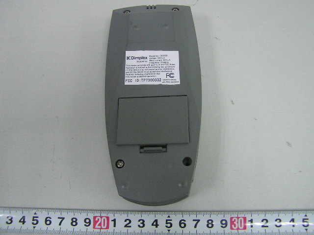
Remote Controller - FCC ID TP730032 - Dimplex North America LTD
TP730032

Remote Controller

Nov 09, 2005

Equipment Class

DXX - Part 15 Low Power Communication Device Transmitter