TPADX6000105Marine Radar
Simrad Stovring AS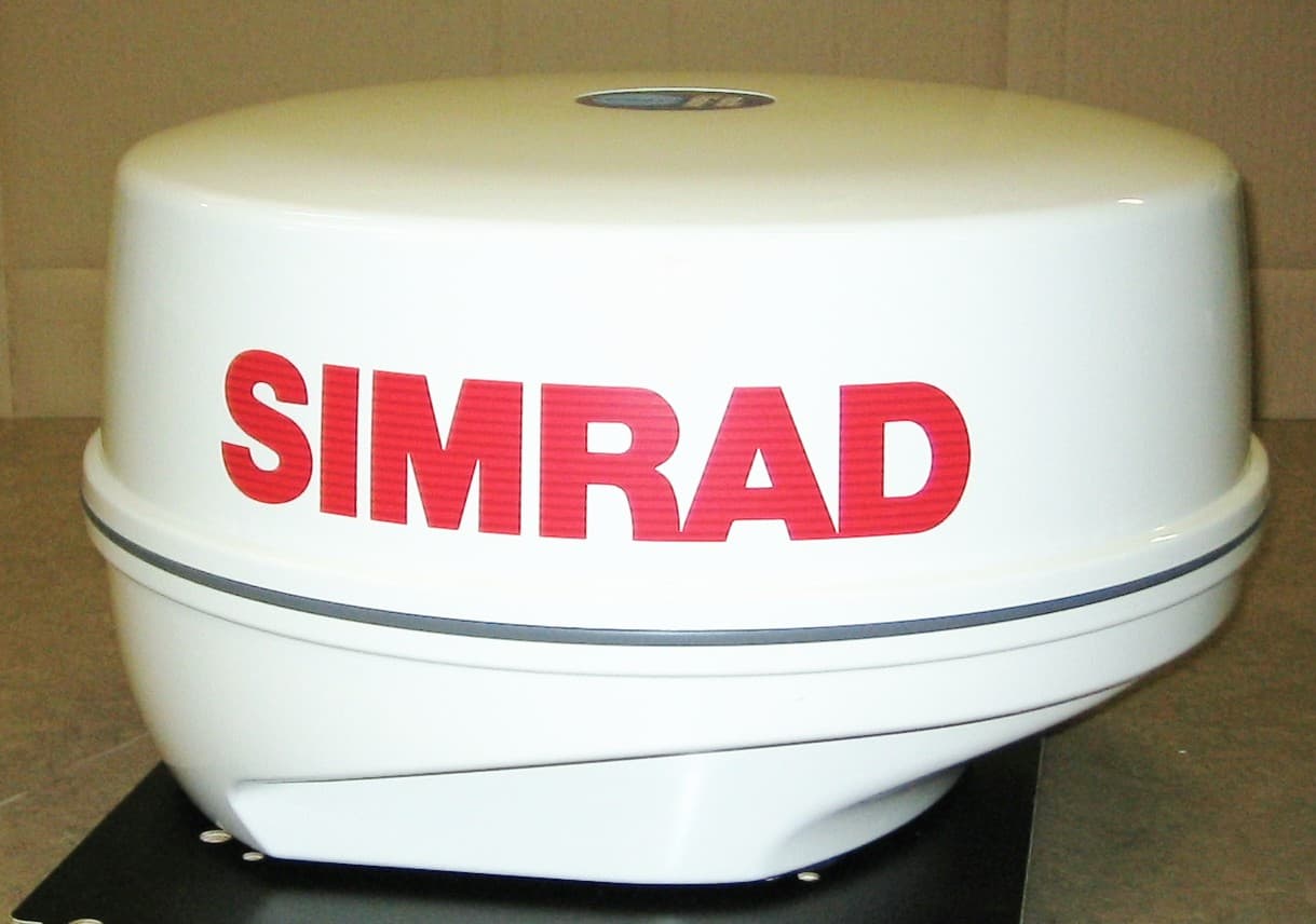
Click to zoom
Application Details
- Equipment Class
- MRD - Marine Radar
- Date of Grant
- Jan 03, 2006
- Application Purpose
- Original Equipment
- Date of Application
- Jan 03, 2006
- Equipment Note
- Marine Radar
- Frequency Range
- 9300.00000000 - 9500.00000000
- Company
- Simrad Stovring AS
- Country
- Denmark
Documents & Files
Document Text
Text extracted from the exhibit documents filed with the FCC. Open a document above to read the original.
Users Manual
INSTALLATION MANUAL SIMRAD DX45/60 Marine Radar Scanner 183-xxxx-102 English Preliminary Important information and warnings! The active radar scanner radiates powerful RF energy. Continuous exposure to RF energy may cause harmful effects to the human body. It also causes Cardiac Pacemaker to malfunction. A person who uses a Cardiac Pacemaker should under no circumstances be exposed to RF radiation. Most countries accept that RF power density levels below 100 W/m 2 cause no significant RF hazard. Please read the Safety Notices on the next page. Page-II About this manual The technical data, information and illustrations contained in this publication were to the best of our knowledge correct at the time of going to print. We reserve the right to change specifi cations, equipment, installation and maintenance instructions without notice as part of our policy of continuous development and improvement. No part of this publication may be reproduced, stored in a retrieval system or transmitted in any form, electronic or otherwise without prior permission from Simrad AS. No liability can be accepted for any inaccuracies or omissions in the publication, although every care has been taken to make it as complete and accurate as possible. This manual provides information for installation, safety notices and mainte- nance safety of the radar scanner DX45/60. The installation will require connection to a compatible display unit: CX34/44/54. A typical radar system is illustrated below: Radar scanner Display unit GPS antenna Compass 12/24 Volt supply AT44 12 Volt supply SimNet Safety notices Beware of RF radiation hazard The active radar scanner radiates powerful RF energy. Continuous exposure to RF energy may cause harmful effects to the human body. It also causes Cardiac Pacemaker to malfunction. A person who uses a Cardiac Pacemaker should under no circumstances be exposed to RF radiation. Page-III Most countries accept that RF power density levels below 100 W/m 2 cause no significant RF hazard. Distance vs. specified RF power density level: Power / scanner size100 W/m 2 10 W/m 2 4 kW / 1.5 ft. / 465 mm x.x mx.x m 4 kW / 2.0 ft. / 615 mm x.x mx.x m Precaution Do not open the equipment, only authorized Simrad technicians are qualifi ed to do so. There is high voltage present inside the scanner which may also be present even after the power switch has been turned off. Power source, fuse and power cable The radar scanner will get its power from the display unit. Ensure that the power cable is fi rmly attached to the appropriate port on the display unit. Note: the appropriate fuse(s) must be employed, see fuse rating in the specifi cations. Maintenance safety Beware of residual high voltages High voltages may remain in the capacitors several minutes after you have turned the power switch off and disconnected the cable between the radar scanner and display unit. Wait for at least five minutes or discharge them to ground before starting your inspection. Main power supply must be disconnected To prevent electrical injury due to erroneous power switching, make sure that the main power supply and the system power switch are both OFF. Also attach a safety label showing that service is in progress. Avoid inhaling dust When cleaning inside of the equipment, avoid inhaling the dust, as it could be a temporary health hazard. Avoid static electricity Take care not to damage the ESDs (Electrostatic Sensitive Devices) due to static electricity from carpeting and clothing. Routine check Periodically check that the scanner’s mounting bolts are tight and not cor- roded. Every 6-12 months an even coating of grease should be applied to the entire surface of the scanner drive gear with a spatula or brush. Most of the maintenance of the radar scanner should be left to qualified personnel. If there are problems with the performance, please contact your authorized dealer. Surface cleaning Wipe the scanner surfaces with a clean damp cloth. For heavier cleaning, use a clean, damp cloth which has been dipped in a solution of mild dish detergent and water. Wring out firmly before wiping the scanner. ) Never use cleaning solutions containing spirit, alcohol, gasoline or oils. Repair and service There are no user serviceable parts in the radar scanners. Unauthorized handling of the scanner will void its warranty. If your radar scanner requires servicing or repair, call your authorized SIMRAD dealer, but first check Troubleshooting on next page. Troubleshoot i ng SymptomPossible causeSuggested solution Scanner is not respond- ing. Cable is damaged or not firmly attached to display unit. Check that the cable connecting the scanner to the display unit is firmly attached: turn the plug as far as it will go into the receptacle marked ‘RADAR’ on the rear of the cabinet and turn the plug’s coupling ring clockwise until it’s tight. Echo image on radar display differs from actual image. Ship’s heading is incor- rect. Adjust ship’s heading* Echo images on radar display are blurred. Gain, Sea or Rain set- tings may be incorrect. Adjust Gain, Sea or Rain* Too much noise in radar display. Tuning setting may be incorrect. Adjust tuning* Alarm/warning appears on radar display. See below list of alarms/ warnings. *) refer to procedure described in display unit’s Operator manual, section 9.1. Page-IV List of alarms/warnings - Bearing pulse alarm (check if scanner is rotating) - Bearing zero alarm (check if scanner is rotating) - Changing to Head-Up alarm (indicates the orientation mode has changed - see section 3.2.5 and 3.2.7*) - Communication failure alarm (check connection to scanner) - Communication time-out failure alarm (no communication between display and scanner) - Guard Zone alarm (see GZ under section 3.2.5*) - Heading missing alarm (check connection to compass) - Position missing alarm (see Position update under section 6.3*) - Rotation lock alarm (check if scanner is rotating) - Trigger fail alarm (check connection to scanner) *) refer …
Text truncated - open the document above for the full version.
Cover Letter(s)
Date Nov 30 th 2005 Telecommunication Certification Body RFI Global Services Ltd. Pavilion A Ashwood Park Basingstoke Hampshire RG23 8BG United Kingdom Subject: Certification Application FCC ID: TPADX6000105 1. Identification of the specific information for which confidential treatment is sought: It is requested that the following information is to be held confidential on behalf of Simrad Stovring AS. FCC Rules Part 0.459 refers. Schematic diagram 1 file 12 pages “Schematic DX 45 and 60.pdf” Partlists 1 file 10 pages “Partlists DX45 and 60.pdf” PCB layout 1 file 20 pages “PCB DX45 and 60.pdf” Operational description 1file 4 pages “Operational description.pdf” Mainbord circuit 1file 10 pages ”Mainboard Circuit description-3477.pdf” 2. Identification of the Commission proceeding in which the information was submitted or a description of the circumstances giving rise to the submission: The proceeding is that involving the application for equipment authorization (certification) under FCC ID No: TPADX6000105 3. Explanation of the degree to which the information is commercial or financial, or contains a trade secret or is privileged: This material includes a detailed theory of operation, circuit diagrams, and schematics. As such, this material is treated as highly confidential business information and not available as general information. 4. Explanation of the degree to which the information concerns a service that is subject to competition: The material for which confidentiality is sought is employed in the design and manufacture of this transmitting equipment that is offered on a highly competitive basis. Customers for this equipment have a variety of competing sources. 5. Explanation of how disclosure of the information could result in substantial competitive harm: Disclosure would, in effect, give away Simrads investment in this product. 6. Identification of any measures taken by the submitting party to prevent unauthorized disclosure: The information for which confidential treatment is sought is kept confidential by Simrad and not made available to third parties except pursuant to non-disclosure agreements. 7. Identification of whether the information is available to the public and the extent of any previous disclosure of the information to third parties: To the knowledge of those preparing this application, the information has not been disclosed publicly before. The general theory of operation of this equipment has been the subject of numerous disclosures with suppliers and consultants. 8. Justification of the period during which the submitting party asserts that the material should not be available for public disclosure: This material should not be disclosed for at least 10 years. While improvements in design are made relatively frequently, disclosure of the design information would lead to insights into both design and manufacturing techniques that could have an adverse competitive effect for many years to come. This equipment is designed for commercial, industrial, and governmental applications. As such, unlike most consumer equipment, this equipment could be used for more than a decade in some cases. As such, it is important that the design not be made available to unauthorized persons who might attempt to use knowledge of the design to compromise the applications for which the equipment will be employed. Yours sincerely René Østergaard Hardware Manager Simrad Støvring AS Østre Alle 6 DK-9530 Støvring Denmark
Cover Letter(s)
Question: Section 7.2.7 of the report lists a conducted emission level of -13.7dBm (for 700ns setting). The corresponding plot does not seem to have a significant emission at that frequency. Please clarify how average emission levels are computed as listed in that section. Response from Test Lab: Having study the plots mentioned and revising the recorded data. It seems I have a typographical mistake with the results in this section. The result was supposed to be – 23.7dBm rather then –13.7dBm. This was not obtained by calculation. It was in fact, taken from the analyser with an average detector when I closed into the identified emission. As for the 70ns pulse setting reading, this was just a noise floor measurement, as the emission was below the receiver noise floor. During this measurement I have only take into account of the losses of the attenuators, test fixture and cables, which is coupled to the EUT’s antenna port and the measurement receiver. To resolve this matter, I will inform the secretaries to update the old report with the results amended. Question: Please address the same issue with an example calculation for the radiated emissions readings listed in section 7.2.8 of the report. Response from Test Lab: As for the radiated emissions measurements, I have taken the same approach to obtain the emissions average level instead of calculating it from the peak values. The plots shown within the reports were only preliminary scans made with peak detectors and trace Max Hold. Identified emissions were then closed in and measured using an average detector function. The levels were than recorded; with the antenna factors, cable loss and the correction factor of 95.2dB (correction factor for converting field strength at 3 metre to dBm EIRP) at the measured frequencies taken into account.
External Photos
DX45 60 Photo external List of figures: Figure 1 DX45 scanner.............................................................................................................................................................1 Figure 2 DX60 Dome scanner..................................................................................................................................................1 Figure 1 DX45 scanner Figure 2 DX60 Dome scanner Init: ROS Saved: 05-11-11 12:35 Printed: 05-11-11 12:55 by ROS Page 1 of 1 File: C:\Documents and Settings\ROS\Skrivebord\DX45_60 Photo external.doc
ID Label/Location Info
SIMRAD Stovring A/S, OGG Dec. 21st 2005 Reference: Equipment Under Test (EUT): DX60 RFI Quote/Job Number: 47603JD01 Test Description: FCC Part 80 and RSS-138 FCC ID: TPA DX6000105 Date: Dec. 21 st 2005 Label visibility and durability The label carrying the FCC ID and other information is placed on the outside of the enclosure of the DX45 and DX60, as shown in photos below. The label is readily visible and readable. The label material and the method of imprinting are of such quality, that readability for at least 10 years under normal maritime conditions is ensured. The adhesive prohibits removal of the label without the application of grinding or cutting tools. Ole Gregersen Radar Project manager Simrad Stovring A/S Ostre Alle 6 DK-9530 Stovring Denmark Telephone +45 9986 5100 Following pages: Photographs showing the position of the FCC-ID label on the exterior of the products. Statement from the manufacturer of the label in question. FCC ID label placement List of figures: Figure 1 DX45 scanner FCC ID label placement.....................................................................................................................1 Figure 2 DX60 scanner FCC ID label placement.....................................................................................................................1 Figure 1 DX45 scanner FCC ID label placement Figure 2 DX60 scanner FCC ID label placement Init: ROS Saved: 05-12-21 23:59 Printed: 05-12-22 00:00 by ROS Page 1 of 1 File: F:\Projekt\P32\Projektmappe\Godkendelser\Dokumentation til FCC DXxx\Krav 11 til 12 ROS\DX45_60 Photo label placement.doc Simrad Shipmate A/S Østre Allé 6 9530 Støvring Att.: Hans Fischer Aalborg, den 21. december 2005 Melsen Tryk A/S kan garantere 10 års holdbarhed trykt med silkschreen på 3M 7940 folie. / Melsen Tryk A/S garanties 10 years validity of print with silkschreen at 3M 7940 foil. Med venlig hilsen/best regrads Melsen Tryk A/S Kurt Møller
ID Label/Location Info
DX45 60 Photo label FCC ID List of figures: Figure 1 Label DX45................................................................................................................................................................1 Figure 2 Label DX60................................................................................................................................................................1 Figure 1 Label DX45 Figure 2 Label DX60 Label measurements are 24 x 110 mm Init: ROS Saved: 05-11-24 13:21 Printed: 05-11-24 13:21 by ROS Page 1 of 1 File: F:\Projekt\P32\Projektmappe\Godkendelser\Dokumentation til FCC DXxx\Krav 11 til 12 ROS\DX45_60 Photo Label.doc
Internal Photos
DX45 60 Photo internal List of figures: Figure 1 DX45 scanner.............................................................................................................................................................1 Figure 2 DX60 Dome scanner..................................................................................................................................................2 Figure 3 DX 45/60 absorber removed......................................................................................................................................2 Figure 4 DX 45/60 Antenna removed.......................................................................................................................................3 Figure 5 DX 45/60 Electronics removed..................................................................................................................................3 Figure 6 Antenna unit opposite side.........................................................................................................................................4 Figure 7 Electronics unit oposite side.......................................................................................................................................4 Figure 8 Mainboard 3477 component side...............................................................................................................................5 Figure 9 Mainborad 3477 solder side.......................................................................................................................................6 Figure 10 IF board 3476 component side.................................................................................................................................7 Figure 11 IF Board 3476 solder side........................................................................................................................................7 Figure 12 FE unit 3482 side 1...................................................................................................................................................8 Figure 13 FE unit 3482 side 2...................................................................................................................................................9 Figure 1 DX45 scanner Init: ROS Saved: 05-11-15 13:28 Printed: 05-11-15 13:28 by ROS Page 1 of 9 File: F:\Projekt\P32\Projektmappe\Godkendelser\Dokumentation til FCC DXxx\Krav 11 til 12 ROS\DX45_60 Photo internal.doc DX45 60 Photo internal Figure 2 DX60 Dome scanner Figure 3 DX 45/60 absorber removed Init: ROS Saved: 05-11-15 13:28 Printed: 05-11-15 13:28 by ROS Page 2 of 9 File: F:\Projekt\P32\Projektmappe\Godkendelser\Dokumentation til FCC DXxx\Krav 11 til 12 ROS\DX45_60 Photo internal.doc DX45 60 Photo internal Figure 4 DX 45/60 Antenna removed Figure 5 DX 45/60 Electronics removed Init: ROS Saved: 05-11-15 13:28 Printed: 05-11-15 13:28 by ROS Page 3 of 9 File: F:\Projekt\P32\Projektmappe\Godkendelser\Dokumentation til FCC DXxx\Krav 11 til 12 ROS\DX45_60 Photo internal.doc DX45 60 Photo internal Figure 6 Antenna unit opposite side Figure 7 Electronics unit oposite side Init: ROS Saved: 05-11-15 13:28 Printed: 05-11-15 13:28 by ROS Page 4 of 9 File: F:\Projekt\P32\Projektmappe\Godkendelser\Dokumentation til FCC DXxx\Krav 11 til 12 ROS\DX45_60 Photo internal.doc DX45 60 Photo internal Figure 8 Mainboard 3477 component side Init: ROS Saved: 05-11-15 13:28 Printed: 05-11-15 13:28 by ROS Page 5 of 9 File: F:\Projekt\P32\Projektmappe\Godkendelser\Dokumentation til FCC DXxx\Krav 11 til 12 ROS\DX45_60 Photo internal.doc DX45 60 Photo internal Figure 9 Mainborad 3477 solder side Init: ROS Saved: 05-11-15 13:28 Printed: 05-11-15 13:28 by ROS Page 6 of 9 File: F:\Projekt\P32\Projektmappe\Godkendelser\Dokumentation til FCC DXxx\Krav 11 til 12 ROS\DX45_60 Photo internal.doc DX45 60 Photo internal Figure 10 IF board 3476 component side Figure 11 IF Board 3476 solder side Init: ROS Saved: 05-11-15 13:28 Printed: 05-11-15 13:28 by ROS Page 7 of 9 File: F:\Projekt\P32\Projektmappe\Godkendelser\Dokumentation til FCC DXxx\Krav 11 til 12 ROS\DX45_60 Photo internal.doc DX45 60 Photo internal Figure 12 FE unit 3482 side 1 Init: ROS Saved: 05-11-15 13:28 Printed: 05-11-15 13:28 by ROS Page 8 of 9 File: F:\Projekt\P32\Projektmappe\Godkendelser\Dokumentation til FCC DXxx\Krav 11 til 12 ROS\DX45_60 Photo internal.doc DX45 60 Photo internal Figure 13 FE unit 3482 side 2 Init: ROS Saved: 05-11-15 13:28 Printed: 05-11-15 13:28 by ROS Page 9 of 9 File: F:\Projekt\P32\Projektmappe\Godkendelser\Dokumentation til FCC DXxx\Krav 11 til 12 ROS\DX45_60 Photo internal.doc
Test Report
TEST REPORT FROM RFI GLOBAL SERVICES LTD Test of: Simrad Stovring. DX60. To: FCC Part 80 2005 Test Report Serial No: RFI\MPTE3\RP47603JD01A Supersedes Test Report Serial No: RFI\MPTE2\RP47603JD01A This Test Report Is Issued Under The Authority Of Andrew Brown, Operations Manager: Tested By: Steven Wong Checked By: Tony Henriques Report Copy No: PDF01 Issue Date: 03 January 2006 Test Dates: 10 October 2005 to 28 October 2005 This report is issued in Adobe Acrobat portable document format (PDF). It is only a valid copy of the report if it is being viewed in PDF format with the following security options not allowed: Changing the document, Selecting text and graphics, Adding or changing notes and form fields. This report may be copied in full. The results in this report apply only to the sample(s) tested. RFI GLOBAL SERVICES LTD TEST REPORT S.No. RFI\MPTE3\RP47603JD01A Page 2 of 56 Issue Date: 03 January 2006 Test of: Simrad Stovring. DX60. To: FCC Part 80 2005 This page has been left intentionally blank. Test Report Serial No: RFI\MPTE3\RP47603JD01A Supersedes Test Report Serial No: RFI\MPTE2\RP47603JD01A RFI GLOBAL SERVICES LTD TEST REPORT S.No. RFI\MPTE3\RP47603JD01A Page 3 of 56 Issue Date: 03 January 2006 Test of: Simrad Stovring. DX60. To: FCC Part 80 2005 Table of Contents 1. Client Information .............................................................................................................4 2. Equipment Under Test (EUT) ...........................................................................................5 3. Test Specification, Methods and Procedures ................................................................8 4. Deviations from the Test Specification...........................................................................9 5. Operation of the EUT During Testing............................................................................10 6. Summary of Tests ...........................................................................................................11 7. Measurements, Examinations and Derived Results ....................................................12 8. Measurement Uncertainty ..............................................................................................44 9. Measurement Methods ...................................................................................................45 Appendix 1. Test Equipment Used ....................................................................................55 RFI GLOBAL SERVICES LTD TEST REPORT S.No. RFI\MPTE3\RP47603JD01A Page 4 of 56 Issue Date: 03 January 2006 Test of: Simrad Stovring. DX60. To: FCC Part 80 2005 1. Client Information Company Name: Simard Stovring Address: Ostre Alle 6 Stovring DK-9530 Contact Name: Mr R Ostergaard RFI GLOBAL SERVICES LTD TEST REPORT S.No. RFI\MPTE3\RP47603JD01A Page 5 of 56 Issue Date: 03 January 2006 Test of: Simrad Stovring. DX60. To: FCC Part 80 2005 2. Equipment Under Test (EUT) The following information (with the exception of the Date of Receipt) has been supplied by the client: 2.1. Identification of Equipment Under Test (EUT) Brand Name: Simard Model Name or Number: DX60 Serial Number: 15 FCC ID Number: TPADX6000105 Country of Manufacture: Denmark Date of Receipt: 10 October 2005 2.2. Description of EUT The equipment under test is a radar scanner for non-solas maritime applications. 2.3. Modifications Incorporated in EUT During the transmitter testing, the EUT antenna was removed and replaced with a waveguide coupler with 30dB of attenuation. This was done in order to allow access to the magnetron output (antenna port) and provide sufficient attenuation to the transmitter power. Any losses incurred with test fixtures were accounted for in the final data. RFI GLOBAL SERVICES LTD TEST REPORT S.No. RFI\MPTE3\RP47603JD01A Page 6 of 56 Issue Date: 03 January 2006 Test of: Simrad Stovring. DX60. To: FCC Part 80 2005 2.4. Additional Information Related to Testing Power Supply Requirement: DC Supply of 12 V Intended Operating Environment: Maritime Vessel Equipment Category: Maritime Radar Type of Unit: Fixed Maritime. Transmit Frequency Range: N/A Single Channel Channel ID Channel Number Channel Frequency (MHz) Transmit Channels Tested: Single Frequency N/A 9410 Receive Frequency Range: N/A Single Channel Channel ID Channel Number Channel Frequency (MHz) Receive Channels Tested: Single Frequency N/A 9410 Maximum Mean Power Output 34.2 dBm 2.5. Port Identification Port Description Type/Length Applicable 1 Display Unit Interface Port 15 m, Multi-core Y RFI GLOBAL SERVICES LTD TEST REPORT S.No. RFI\MPTE3\RP47603JD01A Page 7 of 56 Issue Date: 03 January 2006 Test of: Simrad Stovring. DX60. To: FCC Part 80 2005 2.6. Support Equipment No support equipment was used to exercise the EUT during testing. RFI GLOBAL SERVICES LTD TEST REPORT S.No. RFI\MPTE3\RP47603JD01A Page 8 of 56 Issue Date: 03 January 2006 Test of: Simrad Stovring. DX60. To: FCC Part 80 2005 3. Test Specification, Methods and Procedures 3.1. Test Specifications Reference: FCC Part 80 2005 Title: Code of Federal Regulations, Part 80 (47CFR80) Stations in the Maritime Services. 3.2. Methods and Procedures The methods and procedures used were as detailed in: ANSI C63.2 (1987) Title: American National Standard for Instrumentation - Electromagnetic noise and field strength. ANSI C63.4 (2003) Title: American National Standard Methods of Measurement of Electromagnetic Emissions from Low Voltage Electrical and Electronic Equipment in the Range of 9 kHz to 40 GHz. ANSI C63.5 (1988) Title: American National Standard for the Calibration of antennas used for Radiated Emission measurements in Electromagnetic Interference (EMI) control. ANSI C63.7 (1988) Title: American National Standard Guide for Construction of Open Area Test Sites for performing Radiated Emission Measurements. CISPR 16-1: (1999) Title: Specification For Radio Disturbance and Immunity Measuring Apparatus and Methods. Part 1: Radio Disturba…
Text truncated - open the document above for the full version.
Contact Information
Applicant
Ole Gregers Gregersen
Test Firm
RFI Global Services Ltd.Allan Hume
Technical Specifications
| # | Rule Parts | Frequency Range | Power Output | Emission |
|---|---|---|---|---|
| 1 | 80 | 9.30 GHz - 9.50 GHz | 4000 W | 52M6P0N |