TPYTRM801WIRELESS MICROPHONE
Logitek Standard Electronics Cable Manufacturing Co., Ltd.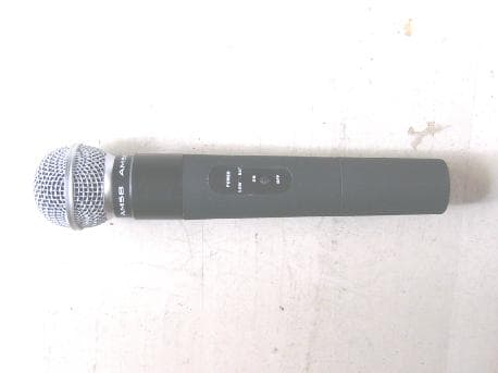
Click to zoom
Application Details
- Equipment Class
- TBF - Licensed Broadcast Transmitter Held to Face
- Date of Grant
- Oct 19, 2005
- Application Purpose
- Original Equipment
- Date of Application
- Oct 19, 2005
- Equipment Note
- WIRELESS MICROPHONE
- Frequency Range
- 801.78500000 - 801.78500000
- Country
- China
Documents & Files
Document Text
Text extracted from the exhibit documents filed with the FCC. Open a document above to read the original.
Users Manual
***************Foreword*************** Thanks for your support and trust to buy professional wireless microphone products. Please read this user’s manual carefully before using in order to exert the ultimate effect and store this manual in a safe place after reading for future reference. Our products is used in the entertainment places as a larger and a middle and small stage, karaoke hall, meeting room, classroom or at home. ***************CONTENTS***************** FOREWORD ------------------------------------------------------------------------------------------- 1 GRAPHIC ILLUSTRATION------------------------------------------------------------------------ 2 SPECIFICATION ILLUSTRATION ------------------------------------------------------------------ 3 OPERATION INTRODUCTION ------------------------------------------------------------------ 5 USE CAUTIONS --------------------------------------------------------------------------------------- 6 1) RECEIVER MODULE FRONT PART INTRODUCTION 1. antenna 2. AF signal lamp 3. RF signal lamp 4. Main volume adjustment knop (1) (2) (3) (4) 2) RECEIVER MODULE BACK PART INTRODUCTION 5. AF signal lamp output 6. RF signal lamp output 7. DC power 9V output 8. AF audio signal output 9. GND (5) (6) (7)(8)(9) 3) RECEIVER MODULE FRAMEWORK 4) MICROPHONE INTRODUCTION 10. catridge head 11. power lamp 12. thin power lamp 13. power switch 14. battery cover (10) (11)(12) (13) (14) 5) MICROPHONE FRAMEWORK *********************SPECIFICATION ILLUSTRATION*************************** MICROPHONE FEATURES AND SPECIFICATION A. frequency: 801.8MHz B. antenna: Built in C. maximum deviation range: ±30KHz D. power output: 10mW E. accord wave radiation: <45dB F. power: Standard 9V battery G. consumed current: 35mA H. pick up sound: cardioid pattern RECEIVER FEATURE AND SPECIFICATION A. quartz crystal shaking aptotic frequency reveiver B. sensitivity: 10Bd /uV C. S/N ratio: >90dB D. Feint interference ratio: >80dB E. Voltage: DC12V,100mA F. Audio output: 200mV OVERALL SYSTEM A. Frequency range: 801.8MHz B. Frequency stability: ±0.005% C. Maximum deviation range: ±30KHz D. Frequency response: 30HZ-15Hz E. S/N ratio: >90dB T.H.D:<1%@1KHz F. Audio yard locked: 32.768KHz **************************OPERATION INTRODUCTION************************* 1. Connect the power supply positive to the socket at the back side of the receiver(7), negative to (9) , then connect the power supply to appointed voltage AC socket. 2. Audio output connecting connect the one side of the cable insert the back side audio output (8), another insert KTV OR amplifier “MIC IN” socket. 3. Pull out all antennas, adjust them to be 90 angle with the receiver. 4. Open the battery cover and install the 9v battery correctly in the microphone, and then make it tight. 5. Put the microphone transmitter power supply (13) ON, power lamp (11) light, thin power lamp (12) blink instantly, and then extinct, it indicate the microphone transmitter is on the using situation. 6. At the same time one of the receiver RF lamp (3)will light, then adjust the volume knop (4) , if the tone of the receiver is on the normal using volume situation, it finishes the microphone test. 7. When the microphone is on the thin power situation, the thin power lamp(12) will turn on. Then you must give up the microphone transmitter. *****************************USE CAUTIONS********************************** 1. One receiver cannot receive the more than two the same frequency microphone signal or other different frequency microphone signal. It only receives the corresponding frequency microphone signal. Different frequency and different brand microphone cannot use in this receiver. 2. If there are some obstacles between and receiver and transmitter or the situation of the receiver is not very good, it will affect the effect. The best effect is there is nothing between them. 3. Please take away the battery if don’t use the system permanently. 4. Please keep the power adapter socket and sockets on the products clean, you must wipe off the dust. The dust will bring on power connect inadequately and bring several trouble. 5. Do not put the water and other liquids into the main machine in order to avoid the circuit board and other spare parts in damp atmosphere bring short circuit and broken down.
Cover Letter(s)
CONFIDENTIALITY FORM Date: October 18, 2005 Federal Communications Commission 7435 Oakland Mills Road Columbia, MD 21046 Gentlemen: This letter is to comply with Section 0.457(d)(2)(i) and 0.459 pertaining to confidential material. Logitek Standard Electronics Cable Manufacturing Co., Ltd. would like the following documents regarding this submission for FCC ID: TPYTRM801 to be kept confidential. 1. Schematic 2. Block Diagram 3. Operational Description 4. Parts List The above material contains trade secrets or technical data, which would customarily be guarded from competitors. We do not want these documents to be accessible to the general public. Sincerely, Yin Bangyan / QC Manager
External Photos
Applicant: Logitek Standard Electronics Cable Manufacturing Co., Ltd. FCC ID: TPYTRM801 Tx EUT view
ID Label/Location Info
Applicant: Logitek Standard Electronics Cable Manufacturing Co., Ltd. FCC ID: TPYTRM801 This device complies with Part 74 of the FCC Rules. Proposed Label Location on EUT EUT Bottom View/Proposed FCC ID Location FCC ID: TPYTRM801
Internal Photos
Applicant: Logitek Standard Electronics Cable Manufacturing Co., Ltd. FCC ID: TPYTRM801 Tx EUT inside whole view Tx Main board component side Tx Main board solder side
Parts List/Tune Up Info
Applicant: Logitek Standard Electronics Cable Manufacturing Co., Ltd. FCC ID: TPYTRM801 Tune-UP Procedure 1.Remove battery cover. 2. Insert 1 pieces of 9V to battery terminals. 3. Slide power switch to “on” position while observing LED (green). 4. RF power output adjustment for TRM801 1) Please place TRM801 at 30 cm from Spectrum Analyzer Antenna and PARALLET to antenna. 2) Adjust “L3,L4,VC2,VC3,VC6”, on the TRM801 PCB to obtain power level of less than 105dBuV. 3) Adjust L2 on the TRM801 PCB to obtain the correct frequency ±6KHz. 4) Observe current meter and it should be less than 35mA. 5. TRM801 AF Adjustment 1) Connect a 1KHz and 50mV audio signal to MIC input socket on the TRM801 PCB, then adjust VR2 until the deviation is 15±2KHz. 2) Observe MOD scope for an undistorted sin wave. 6. TRM801 TONE Adjustment 1) Adjust VR1 until the TONE level is 5KHz±1KHz.
Test Report
The test report consists 24 pages in total. It may be duplicated completely for legal use with the allowance of the applicant. It shall not be reproduced except in full, without the written approval of Ke Mei Ou Laboratory Corporation. The test result in the report only applied to the tested sample. FCC TEST REPORT Under FCC Part 74 Subpart H, Prepared For: Logitek Standard Electronics Cable Manufacturing Co., Ltd. Science & Technology Zone, Jiangshan Town, Yinzhou District, Ningbo Zhejiang, China. October 17, 2005 FCC ID: TPYTRM801 EUT: Wireless Microphone Model: TRM 801 Report Type: Original Report Test Engineer: Peter Lin Test Date: October 10, 2005 Review By: Apollo Liu / Manager Ke Mei Ou Laboratory Co., Ltd. 7A, Jiaxiangge, Jiahuixincheng, No.3027, Shennan Rd., Futian, Shenzhen, Guangdong, P.R.China. Zip Code: 518033 Tel: + 86 755 83642690 Fax: + 86 755 83297077 www.kmolab.com FEDERAL COMMUNICATIONS COMMISSION Registration Number: 125782 INDUSTRY CANADA Registration Number: IC4986 Logitek Standard Electronics Cable Manufacturing Co., Ltd. FCC ID: TPYTRM801 FCC ID Report Report #: KSZ2005082402J Page 2 of 24 TABLE OF CONTENTS 1. General Information....................................................................................................................................................3 1. 1 Notes......................................................................................................................................................................3 1. 2 Testing Laboratory..................................................................................................................................................3 1. 3 Details of Applicant................................................................................................................................................3 1. 4 Application Details..................................................................................................................................................3 1. 5 Test Item.................................................................................................................................................................3 1. 6 Test Standards.........................................................................................................................................................3 2. Technical Test...............................................................................................................................................................4 2. 1 Summary of Test Results.........................................................................................................................................4 3. EUT Modifications.......................................................................................................................................................4 4. Conducted Power Line Test.........................................................................................................................................5 4. 1 Test Equipment.......................................................................................................................................................5 4. 2 Test Procedure........................................................................................................................................................5 4. 3 Test Setup...............................................................................................................................................................5 4. 4 Configuration of The EUT.......................................................................................................................................6 4. 5 EUT Operating Condition........................................................................................................................................7 4. 6 Conducted Power Line Emission Limits..................................................................................................................7 4. 7 Conducted Power Line Test Result...........................................................................................................................7 5. Output Power Measurement........................................................................................................................................8 5. 1 Test Equipment.......................................................................................................................................................8 5. 2 Test Procedure........................................................................................................................................................8 5. 3 Test Setup...............................................................................................................................................................8 5. 4 Configuration of The EUT.......................................................................................................................................9 5. 5 EUT Operating Condition........................................................................................................................................9 5. 6 Rules and Specification Limits................................................................................................................................9 5. 7 Output Power Test Result........................................................................................................................................9 5. 8 Result Calculation...................................................................................................................................................9 6. Modulation Characteristics.......................................................................................................................................10 6. 1 Test Equipment.......................................................................…
Text truncated - open the document above for the full version.
Test Setup Photos
Applicant: Logitek Standard Electronics Cable Manufacturing Co., Ltd. FCC ID: TPYTRM801 Radiated emission test view
Contact Information
Applicant
Lane Shaw
Test Firm
Ke Mei Ou Laboratory Co., Ltd.Apollo Liu
Technical Specifications
| # | Rule Parts | Frequency Range | Power Output | Emission | Tolerance |
|---|---|---|---|---|---|
| 1 | 74.861 | 801.785 MHz - 801.785 MHz | 390.00 µW | 116KF3E | 0.0050000000 % |
Other Applications from Logitek Standard Electronics Cable Manufacturing Co., Ltd.

TPYDX-M1114
Jun 14, 2006WIRELESS MICROPHONE
Equipment Class
TBF - Licensed Broadcast Transmitter Held to Face
TPYDX-M1113
Jun 14, 2006WIRELESS MICROPHONE
Equipment Class
TBF - Licensed Broadcast Transmitter Held to Face