TQ8-AC244HGANDIGITAL CAR AUDIO SYSTEM
HYUNDAI MOBIS CO., LTD.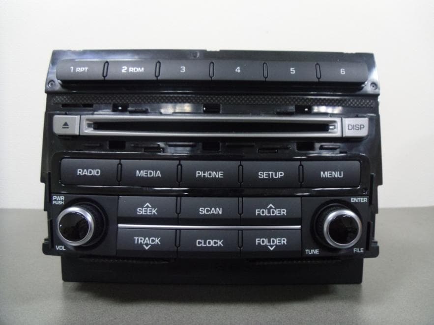
Click to zoom
Application Details
- Equipment Class
- DSS - Part 15 Spread Spectrum Transmitter
- Date of Grant
- Feb 12, 2014
- Application Purpose
- Original Equipment
- Date of Application
- Feb 12, 2014
- Equipment Note
- DIGITAL CAR AUDIO SYSTEM
- Frequency Range
- 2402.00000000 - 2480.00000000
- Company
- HYUNDAI MOBIS CO., LTD.
- Country
- South Korea
Documents & Files
Document Text
Text extracted from the exhibit documents filed with the FCC. Open a document above to read the original.
Users Manual
41 Features of your vehicle How vehicle audio works AM and FM radio signals are broad- cast from transmitter towers located around your city. They are intercept- ed by the radio antenna on your vehi- cle. This signal is then processed by the radio and sent to your vehicle speakers. When a strong radio signal has reached your vehicle, the precise engineering of your audio system ensures the best possible quality reproduction. However, in some cas- es the signal coming to your vehicle may not be strong and clear. This can be due to factors, such as the distance from the radio station, closeness of other strong radio sta- tions or the presence of buildings, bridges or other large obstructions in the area. AM broadcasts can be received at greater distances than FM broad- casts. This is because AM radio waves are transmitted at low fre- quencies. These long distance,low frequency radio waves can follow the curvature of the earth rather than travelling straight. In addition, they curve around obstructions resulting in better signal coverage. JBM002 AM reception JBM001 FM reception Features of your vehicle 24 FM broadcasts are transmitted at high frequencies and do not bend to follow the earth's surface. Because of this, FM broadcasts generally begin to fade within short distances from the station. short distances from the station. Also, FM signals are eas- ily affected by buildings, mountains, and obstructions. This can lead to undesirable or unpleasant listening conditions which might lead you to believe a problem exists with your radio. The following conditions are normal and do not indicate radio trouble: • Fading - As your vehicle moves away from the radio station, the signal will weaken and sound will begin to fade. When this occurs, we suggest that you select another stronger station. • Flutter/Static - Weak FM signals or large obstructions between the transmitter and your radio can dis- turb the signal causing static or fluttering noises to occur. Reducing the treble level may lessen this effect until the disturbance clears. • Station Swapping - As an FM sig- nal weakens, another more power- ful signal near the same frequency may begin to play. This is because your radio is designed to lock onto the clearest signal. If this occurs, select another station with a stronger signal. • Multi-Path Cancellation - Radio signals being received from sever- al directions can cause distortion or fluttering. This can be caused by a direct and reflected signal from the same station, or by signals from two stations with close fre- quencies. If this occurs, select another station until the condition has passed. JBM003 FM radio station JBM005 JBM004 43 Features of your vehicle Using a cellular phone or a two-way radio When a cellular phone is used inside the vehicle, noise may be produced from the audio system. This does not mean that something is wrong with the audio equipment. In such a case, try to operate mobile devices as far from the audio equipment as possi- ble. Caring for disc • If the temperature inside the car is too high, open the car windows to venti- late before using the system. • It is illegal to copy and use MP3/WMA files without permission. Use CDs that are created only by lawful means. • Do not apply volatile agents, such as benzene and thinner, normal cleaners and magnetic sprays made for analogue disc onto CDs. • To prevent the disc surface from getting damaged, hold CDs by the edges or the center hole only. • Clean the disc surface with a piece of soft cloth before playback (wipe it from the center to the outside edge). • Do not damage the disc surface or attach pieces of sticky tape or paper. • Make certain only CDs are insert- ed into the CD player (Do not insert more than one CD at a time). • Keep CDs in their cases after use to protect them from scratches or dirt. CAUTION When using a communication system such as a cellular phone or a radio set inside the vehicle, a separate external antenna must be fitted. When a cellular phone or a radio set is used with an internal antenna alone, it may interfere with the vehi- cle's electrical system and adversely affect safe operation of the vehicle. WARNING Do not use a cellular phone while driving. Stop at a safe location to use a cellular phone. Features of your vehicle 44 • Depending on the type of CD- R/CD-RW CDs, certain CDs may not operate normally according to the manufacturing companies. In such circumstances, continued use may cause malfunctions to your audio system. ✽✽ NOTICE - Playing an Incompatible Copy Protected Audio CD Some copy protected CDs, which do not comply with international audio CD standards (Red Book), may not play on your car audio. Please note that inabilities to properly play a copy protected CD may indicate that the CD is defective, not the CD player. NOTE: Order of playing files (folders) : 1. Song playing order :to sequentially. 2. Folder playing order : ❋If no song file is contained in the folder, that folder is not displayed. 45 Features of your vehicle CAUTION • Operating the device while driving could lead to acci- dents due to a lack of atten- tion to external surroundings. First park the vehicle before operating the device. • Adjust the volume to levels that allow the driver to hear sounds from outside of the vehicle. Driving in a state where external sounds cannot be heard may lead to acci- dents. • Pay attention to the volume setting when turning the device on. A sudden output of extreme volume upon turning the device on could lead to hearing impairment. (Adjust the volume to a suitable levels before turning off the device.) (Continued) WARNING • Do not stare at the screen while driving. Staring at the screen for prolonged periods of time could lead to traffic accidents. • Do not disassemble, assem- ble, or modify the audio sys- tem. Such acts could result in accidents, fire, or electric shock. • Using the phone while driving may lead to a lack of attention of traffic conditions and increase the like…
Text truncated - open the document above for the full version.
Cover Letter(s)
Hyundai MOBIS Co., Ltd. 203, Teheran‐ro, Gangnam‐gu, Seoul, 135‐977, Korea Tel. 82‐31‐260‐0092 11 February 2014 Federal Communications Commission Authorization and Evaluation Division 7435 Oakland Mills Road, Columbia, MD 21046 Letter of Authorization We, Hyundai MOBIS Co., Ltd. hereby authorize SGS Korea Co., Ltd. to act on our behalf in all matters of certification. Any and all acts carried out by SGS Korea on our behalf shall have the same effect as acts of our own. This authorization is valid until further written notice. Sincerely, __________________________ Seung Hoon Choe Senior Researcher Hyundai MOBIS Co., Ltd.
Cover Letter(s)
Hyundai MOBIS Co., Ltd. 203, Teheran‐ro, Gangnam‐gu, Seoul, 135‐977, Korea Tel. 82‐31‐260‐0092 11 February 2014 Federal Communications Commission Authorization and Evaluation Division 7435 Oakland Mills Road, Columbia, MD 21046 Request of Confidentiality for FCC ID: TQ8‐AC244HGAN To Whom It May Concern: Pursuant to Sections 0.457 and 0.459 of the Commission’s Rules (CFR 47), and Section 552 (b) (4) of the Freedom of Information Act, Hyundai MOBIS Co., Ltd. hereby requests confidentiality and treatment of certain information accompanying this application. The materials contain trade secrets and proprietary information not customarily released to the public. The public disclosure of these matters might be harmful to the Applicant and provide unjustified benefits to its competitors. We are also hereby request Short‐Term Confidentiality for 180 days after the grant as outlined in Public Notice DA 04‐1705. This provision will give Hyundai MOBIS Co., Ltd. temporary confidentiality of commercially sensitive information prior to product release. The requested Permanent and Temporary Confidential exhibits are listed as follows: CONFIDENTIAL LIST Permanent 1 Block Diagram 2 Operational Descriptions 3 Schematics Short‐Term 4 External Photos 5 Internal Photos 6 Test‐Setup Photos 7 User’s Manual The Applicant understands that pursuant to Rule 0.457, disclosure of this application and all accompanying documentations, where applicable, will not be made public before the date of the Grant for this application. Sincerely, __________________________ Seung Hoon Choe Senior Researcher Hyundai MOBIS Co., Ltd.
External Photos
External photos of EUT Top view of EUT Bottom view of EUT Front view of EUT Rear view of EUT Side view of EUT
ID Label/Location Info
AC244HGANFCC LABEL Information LABEL LOCATION FCC LABEL Information Hyundai MOBIS Co., Ltd. FCC MODEL: AC244HGAN FCC ID: TQ8 ‐ AC244HGAN LABEL LOCATION Nonremovable This device complies with part 15 of the FCC rules and industry Canada license ‐ exempt RSS standard(s). Operation is subject to the following two conditions: (1) This device may not cause harmful interference, and (2) This device must accept any interference received, including interference that may cause undesired operation. LABEL operation.Made in Korea MANUFACTURED BY HYUNDAI MOBIS PRODUCT LABEL FRONT TOP Hyundai MOBIS Co., Ltd.
Internal Photos
Internal photos of EUT Internal view of EUT Top view of Sub PCB Bottom view of Sub PCB Top view of Keypad PCB1 Bottom view of Keypad PCB1 Top view of Keypad PCB2 Bottom view of Keypad PCB2 Top view of Keypad PCB2 Bottom view of Keypad PCB2 Top view of CD Player Bottom view of CD Player Top view of Main PCB (With shilding cap) Top view of Main PCB (Without shilding cap) Bottom view of Main PCB Top view of Bluetooth Antenna Bluetooth Antenna
RF Exposure Info
Report Number : F690501/RF-RTL007394 Page: 2 of 5 The results shown in this test report refer only to the sample(s) tested unless otherwise stated. This test report cannot be reproduced, except in full, without prior written permission of the Company. SGS Korea Co., Ltd. (Gunpo Laboratory) 4, LS-ro 182beon-gil, Gunpo-si, Gyeonggi-do, Korea, 435-040 http://www.sgsgroup.kr RTT5041-20(2014.01.20)(2) Tel. +82 31 428 5700 / Fax. +82 31 427 2370 A4(210 mmx297 mm) INDEX Table of Contents Page 1. General Information -------------------------------------------------------------------------------- 3 2. RF Exposure Evaluation -------------------------------------------------------------------------- 4 Report Number : F690501/RF-RTL007394 Page: 3 of 5 The results shown in this test report refer only to the sample(s) tested unless otherwise stated. This test report cannot be reproduced, except in full, without prior written permission of the Company. SGS Korea Co., Ltd. (Gunpo Laboratory) 4, LS-ro 182beon-gil, Gunpo-si, Gyeonggi-do, Korea, 435-040 http://www.sgsgroup.kr RTT5041-20(2014.01.20)(2) Tel. +82 31 428 5700 / Fax. +82 31 427 2370 A4(210 mmx297 mm) 1. General Information 1.1. Testing Laboratory SGS Korea Co., Ltd. (Gunpo Laboratory) - Wireless Div. 3FL, 4, LS-ro 182beon-gil, Gunpo-si, Gyeonggi-do, Korea, 435-040 - 35, Giheungdanji-ro 121beon-gil, Giheung-gu, Yongin-si, Gyeonggi-do, Korea 446-901 All SGS services are rendered in accordance with the applicable SGS conditions of service available on request and accessible at http://www.sgs.com/en/Terms-and-Conditions.aspx. Phone No. : +82 31 428 5700 Fax No. : +82 31 427 2370 1.2. Details of Applicant Applicant : Hyundai MOBIS Co., Ltd. Address : 203, Teheran-ro, Gangnam-gu, Seoul, 135-977, Korea Contact Person : Choi, Seung-Hoon Phone No. : +82 31 260 0098 1.3. Description of EUT Kind of Product DIGITAL CAR AUDIO SYSTEM Model Name AC244HGAN Power Supply DC 14.4 V Frequency Range 2 402 ㎒ ~ 2 480 ㎒ Modulation Technique GFSK, π/4DQPSK, 8DPSK Number of Channels 79 Antenna Type Chip antenna Antenna Gain -5.83 ㏈i 1.4. Test report revision Revision Report number Description 0 F690501/RF-RTL007394 Initial Report Number : F690501/RF-RTL007394 Page: 4 of 5 The results shown in this test report refer only to the sample(s) tested unless otherwise stated. This test report cannot be reproduced, except in full, without prior written permission of the Company. SGS Korea Co., Ltd. (Gunpo Laboratory) 4, LS-ro 182beon-gil, Gunpo-si, Gyeonggi-do, Korea, 435-040 http://www.sgsgroup.kr RTT5041-20(2014.01.20)(2) Tel. +82 31 428 5700 / Fax. +82 31 427 2370 A4(210 mmx297 mm) 2. RF Exposure Evaluation 2.1. Environmental evaluation and exposure limit according to FCC CFR 47 part 1, 1.1307(b), 1.1310 According to FCC 1.1310 : The criteria listed in the following table shall be used to evaluate the environment impact of human exposure to radio frequency (RF) radiation as specified in §1.1307(b) LIMITS FOR MAXIMUM PERMISSIBLE EXPOSURE (MPE) 2.1.1. Friis transmission formula: Pd = (Pout*G)/(4*pi*R 2 ) Where Pd = power density in ㎽/㎠ Pout = output power to antenna in ㎽ G = gain of antenna in linear scale Pi = 3.1416 R = distance between observation point and center of the radiator in ㎝ Pd the limit of MPE, 1 ㎽/㎠. If we know the maximum gain of the antenna and the total power input to the antenna, through the calculation, we will know the distance where the MPE limit is reached. Frequency Range (㎒) Electric Field Strength(V/m) Magnetic Field Strength (A/m) Power Density (㎽/㎠) Average Time (A) Limits for Occupational /Control Exposures 300 – 1 500 -- -- F/300 6 1 500 – 100 000 -- -- 5 6 (B) Limits for General Population/Uncontrol Exposures 300 – 1 500 -- -- F/1500 6 1 500 – 100 000 -- -- 1 30 Report Number : F690501/RF-RTL007394 Page: 5 of 5 The results shown in this test report refer only to the sample(s) tested unless otherwise stated. This test report cannot be reproduced, except in full, without prior written permission of the Company. SGS Korea Co., Ltd. (Gunpo Laboratory) 4, LS-ro 182beon-gil, Gunpo-si, Gyeonggi-do, Korea, 435-040 http://www.sgsgroup.kr RTT5041-20(2014.01.20)(2) Tel. +82 31 428 5700 / Fax. +82 31 427 2370 A4(210 mmx297 mm) 2.1.2. Test Result of RF Exposure Evaluation Test Item : RF Exposure Evaluation Data Test Mode : Normal Operation 2.1.3. Output Power into Antenna & RF Exposure Evaluation Distance FHSS : GFSK Channel Channel Frequency (㎒) Output Average Power to Antenna (㏈m) Antenna Gain (㏈i) Duty Cycle (%) Power Density at 20㎝ (㎽/㎠) Limits (㎽/㎠) Low 2 402 0.53 -5.83 78 0.000 075 1 Middle 2 441 0.59 -5.83 78 0.000 076 1 High 2 480 0.66 -5.83 78 0.000 078 1 FHSS : 8DPSK Channel Channel Frequency (㎒) Output Average Power to Antenna (㏈m) Antenna Gain (㏈i) Duty Cycle (%) Power Density at 20㎝ (㎽/㎠) Limits (㎽/㎠) Low 2 402 0.31 -5.83 78 0.000 072 1 Middle 2 441 0.42 -5.83 78 0.000 073 1 High 2 480 0.91 -5.83 78 0.000 082 1 Note : 1. The power density Pd (5th column) at a distance of 20㎝ calculated from the friis transmission formula is far below the limit of 1 ㎽/㎠.
Test Report
Report Number: F690501/RF-RTL007393-1 Page: 2 of 65 The results shown in this test report refer only to the sample(s) tested unless otherwise stated. This test report cannot be reproduced, except in full, without prior written permission of the Company. SGS Korea Co., Ltd. (Gunpo Laboratory) 4, LS-ro 182beon-gil, Gunpo-si, Gyeonggi-do, Korea, 435-040 http://www.sgsgroup.kr RTT5041-20(2014.01.20)(2) Tel. +82 31 428 5700 / Fax. +82 31 427 2370 A4(210 mmx297 mm) INDEX Table of Contents Page 1. General Information --------------------------------------------------------------------------------- 3 2. Transmitter Radiated Spurious Emissions and Conducted Spurious Emission ------ 7 3. 20㏈ Bandwidth-------------------------------------------------------------------------------------- 35 4. Maximum Peak Output Power ------------------------------------------------------------------- 42 5. Hopping Channel Separation --------------------------------------------------------------------- 44 6. Number of Hopping Frequency ------------------------------------------------------------------ 47 7. Time of Occupancy(Dwell Time) ----------------------------------------------------------------- 51 8. Antenna Requirement ------------------------------------------------------------------------------ 65 Report Number: F690501/RF-RTL007393-1 Page: 3 of 65 The results shown in this test report refer only to the sample(s) tested unless otherwise stated. This test report cannot be reproduced, except in full, without prior written permission of the Company. SGS Korea Co., Ltd. (Gunpo Laboratory) 4, LS-ro 182beon-gil, Gunpo-si, Gyeonggi-do, Korea, 435-040 http://www.sgsgroup.kr RTT5041-20(2014.01.20)(2) Tel. +82 31 428 5700 / Fax. +82 31 427 2370 A4(210 mmx297 mm) 1. General Information 1.1. Testing Laboratory SGS Korea Co., Ltd. (Gunpo Laboratory) - Wireless Div. 3FL, 4, LS-ro 182beon-gil, Gunpo-si, Gyeonggi-do, Korea, 435-040 All SGS services are rendered in accordance with the applicable SGS conditions of service available on request and accessible at http://www.sgs.com/en/Terms-and-Conditions.aspx. Telephone : +82 31 428 5700 FAX : +82 31 427 2370 1.2. Details of Applicant Applicant : Hyundai MOBIS Co., Ltd. Address : 203, Teheran-ro, Gangnam-gu, Seoul, 135-977, Korea Contact Person : Choi, Seung-Hoon Phone No. : +82 31 260 0098 1.3. Description of EUT Kind of Product DIGITAL CAR AUDIO SYSTEM Model Name AC244HGAN Power Supply DC 14.4 V Frequency Range 2 402 ㎒ ~ 2 480 ㎒ Modulation Technique GFSK, π/4DQPSK, 8DPSK Number of Channels 79 Antenna Type Chip antenna Antenna Gain -5.83 ㏈i 1.4. Declaration by the manufacturer - Adaptive Frequency Hopping is supported and use at least 20 channels Report Number: F690501/RF-RTL007393-1 Page: 4 of 65 The results shown in this test report refer only to the sample(s) tested unless otherwise stated. This test report cannot be reproduced, except in full, without prior written permission of the Company. SGS Korea Co., Ltd. (Gunpo Laboratory) 4, LS-ro 182beon-gil, Gunpo-si, Gyeonggi-do, Korea, 435-040 http://www.sgsgroup.kr RTT5041-20(2014.01.20)(2) Tel. +82 31 428 5700 / Fax. +82 31 427 2370 A4(210 mmx297 mm) 1.5. Information about the FHSS characteristics: 1.5.1. Pseudorandom Frequency Hopping Sequence The channel is represented by a pseudo-random hopping sequence hopping through the 79 RF channels. The hopping sequence is unique for the piconet and is determined by the Bluetooth device address of the master; the phase in the hopping sequence is determined by the Bluetooth clock of the master. The channel is divided into time slots where each slot corresponds to an RF hop frequency. Consecutive hops correspond to different RF hop frequencies. The nominal hop rate is 1 600 hops/s. 1.5.2. Equal Hopping Frequency Use The selection of frequencies is equal from the inventory of available frequencies. 1.5.3. Example of a 79 hopping sequence in data mode: 40, 21, 44, 23, 42, 53, 46, 55, 48, 33, 52, 35, 50, 65, 54, 67, 56, 37, 60, 39, 58, 69, 62, 71, 64, 25, 68, 27, 66, 57, 70, 59, 72, 29, 76, 31, 74, 61, 78, 63, 01, 41, 05, 43, 03, 73, 07, 75, 09, 45, 13, 47, 11, 77, 15, 00, 64, 49, 66, 53, 68, 02, 70, 06, 01, 51, 03, 55, 05, 04 1.5.4. System Receiver Input Bandwidth Each channel bandwidth is 1㎒ 1.5.5. Equipment Description 15.247(a)(1) that the rx input bandwidths shift frequencies in synchronization with the transmitted 15.247(g): In accordance with the Bluetooth Industry Standard, the system is designed to comply with all of the regulations in Section 15.247 when the transmitter is presented with a continuous data (or information) system. 15.247(h): In accordance with the Bluetooth Industry Standard, the system does not coordinate it channels selection/ hopping sequence with other frequency hopping systems for the express purpose of avoiding the simultaneous occupancy of individual hopping frequencies by multiple transmitters. Report Number: F690501/RF-RTL007393-1 Page: 5 of 65 The results shown in this test report refer only to the sample(s) tested unless otherwise stated. This test report cannot be reproduced, except in full, without prior written permission of the Company. SGS Korea Co., Ltd. (Gunpo Laboratory) 4, LS-ro 182beon-gil, Gunpo-si, Gyeonggi-do, Korea, 435-040 http://www.sgsgroup.kr RTT5041-20(2014.01.20)(2) Tel. +82 31 428 5700 / Fax. +82 31 427 2370 A4(210 mmx297 mm) 1.6. Test Equipment List Equipment Manufacturer Model S/N Cal Date Cal Interval Cal Due. Signal Generator R&S SMR40 100540 Jan. 08, 2014 Annual Jan. 08, 2015 Signal Generator Agilent E4438C MY42082477 Mar. 28, 2013 Annual Mar. 28, 2014 Spectrum Analyzer R&S FSV30 101004 Jul. 20, 2013 Annual Jul. 20, 2014 Bluetooth Tester TESCOM TC-3000C 3000C000296 Jul. 02, 2013 Annual Jul. 02, 2014 Directional Coupler KRYTAR 152613 127445 Jul. 02, 2013 Annual Jul. 02, 2014 High Pass Filter Wainwright WHK3.0/18G-6SS 4 Jul. 02, 2013 Annual Jul. 02, 2014 High Pass Filter Wainwright WHK7.5/26.5G-6SS 15 Jul. 03, 2013 Annual Jul…
Text truncated - open the document above for the full version.
Test Setup Photos
Test setup photos of EUT A. Photo of Radiated Spurious Emission Test (9 ㎑ ~ 30 ㎒) B. Photo of Radiated Spurious Emission Test (30 ㎒ ~ 1 ㎓) C. Photo of Radiated Spurious Emission Test (Above 1 ㎓)
Contact Information
Applicant
Seung Hoon Choe(Senior Engineer)
Test Firm
SGS KOREA CO., Ltd.Jackie Jeon
Technical Specifications
| # | Rule Parts | Frequency Range | Power Output |
|---|---|---|---|
| 1 | 15C | 2.40 GHz - 2.48 GHz | 3.20 mW |
Other Applications from HYUNDAI MOBIS CO., LTD.
TQ8-FOB-4FC0M22
Sep 11, 2026FOB Smart Key
Equipment Class
DSC - Part 15 Security/Remote Control TransmitterTQ8-FOB-4FC0M44
Sep 10, 2026FOB Smart Key
Equipment Class
DSC - Part 15 Security/Remote Control TransmitterTQ8-FOB-4FC1U44
Jul 20, 2026FOB Smart Key
Equipment Class
DSC - Part 15 Security/Remote Control TransmitterTQ8-FOB-4FC1M44
Jul 08, 2026FOB Smart Key
Equipment Class
DSC - Part 15 Security/Remote Control TransmitterTQ8-FOB-4FC0U22
Jun 17, 2026FOB Smart Key
Equipment Class
DSC - Part 15 Security/Remote Control Transmitter