TQ8-AM1A0A9ANDIGITAL CAR AUDIO SYSTEM
HYUNDAI MOBIS CO., LTD.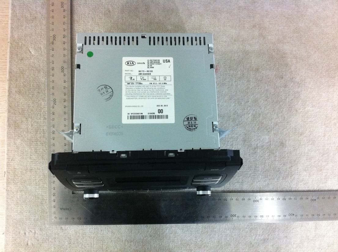
Click to zoom
Application Details
- Equipment Class
- DSS - Part 15 Spread Spectrum Transmitter
- Date of Grant
- Feb 13, 2014
- Application Purpose
- Original Equipment
- Date of Application
- Feb 13, 2014
- Equipment Note
- DIGITAL CAR AUDIO SYSTEM
- Frequency Range
- 2402.00000000 - 2480.00000000
- Company
- HYUNDAI MOBIS CO., LTD.
- Country
- South Korea
Documents & Files
Document Text
Text extracted from the exhibit documents filed with the FCC. Open a document above to read the original.
Users Manual
41 Features of your vehicle How vehicle audio works AM and FM radio signals are broad- cast from transmitter towers located around your city. They are intercept- ed by the radio antenna on your vehi- cle. This signal is then received by the radio and sent to your vehicle speakers. When a strong radio signal has reached your vehicle, the precise engineering of your audio system ensures the best possible quality reproduction. However, in some cases the signal coming to your vehi- cle may not be strong and clear. This can be due to factors, such as the distance from the radio station, closeness of other strong radio sta- tions or the presence of buildings, bridges or other large obstructions in the area. AM broadcasts can be received at greater distances than FM broad- casts. This is because AM radio waves are transmitted at low fre- quencies. These long, low frequency radio waves can follow the curvature of the earth rather than travelling straight out into the atmosphere. In addition, they curve around obstruc- tions so that they can provide better signal coverage. JBM002 AM reception JBM001 FM reception Features of your vehicle 24 FM broadcasts are transmitted at high frequencies and do not bend to follow the earth's surface. Because of this, FM broadcasts generally begin to fade at short distances from the station. Also, FM signals are eas- ily affected by buildings, mountains, or other obstructions. These can result in certain listening conditions which might lead you to believe a problem exists with your radio. The following conditions are normal and do not indicate radio trouble: • Fading - As your vehicle moves away from the radio station, the signal will weaken and sound will begin to fade. When this occurs, we suggest that you select another stronger station. • Flutter/Static - Weak FM signals or large obstructions between the transmitter and your radio can dis- turb the signal causing static or fluttering noises to occur. Reducing the treble level may lessen this effect until the disturbance clears. • Station Swapping - As a FM signal weakens, another more powerful signal near the same frequency may begin to play. This is because your radio is designed to lock onto the clearest signal. If this occurs, select another station with a stronger signal. • Multi-Path Cancellation - Radio signals being received from sever- al directions can cause distortion or fluttering. This can be caused by a direct and reflected signal from the same station, or by signals from two stations with close fre- quencies. If this occurs, select another station until the condition has passed. JBM003 FM radio station JBM005 JBM004 43 Features of your vehicle Using a cellular phone or a two- way radio When a cellular phone is used inside the vehicle, noise may be produced from the audio system. This does not mean that something is wrong with the audio equipment. In such a case, use the cellular phone at a place as far as possible from the audio equip- ment. CAUTION When using a communication system such as a cellular phone or a radio set inside the vehicle, a separate external antenna must be fitted. When a cellular phone or a radio set is used with an internal antenna alone, it may interfere with the vehi- cle's electrical system and adversely affect safe operation of the vehicle. WARNING Do not use a cellular phone while driving. Stop at a safe location to use a cellular phone. Features of your vehicle 44 CAUTION • Operating the device while driving could lead to acci- dents due to a lack of atten- tion to external surroundings. parkthe vehicle before operat- ing the device. • Adjust the volume to levels that allow the driver to hear sounds from outside of the vehicle. Driving in a state where external sounds cannot be heard may lead to acci- dents. • Pay attention to the volume setting when turning the device on. A sudden output of extreme volume upon turning the device on could lead to hearing impairment. (Adjust the volume to a suitable levels before turning off the device.) (Continued) WARNING • Do not stare at the screen while driving. Staring at the screen for prolonged periods of time could lead to traffic accidents. • Do not disassemble, assem- ble, or modify the audio sys- tem. Such acts could result in accidents, fire, or electric shock. • Using the phone while driving may lead to a lack of attention of traffic conditions and increase the likelihood of accidents. Use the phone feature after parking the vehicle. • Heed caution not to spill water or introduce foreign objects into the device. Such acts could lead to smoke, fire, or product malfunction. (Continued) (Continued) • Please refrain from use if the screen is blank or no sound can be heard as these signs may indicate product mal- function.Continued use in such conditions could lead to accidents(fires, electric shock) or product malfunc- tions. • Do not touch the antenna dur- ing thunder or Lightning Suc h acts may cause electric shock by lightning. •Do not stop or park in park- ing-restricted areas to operate the product. Such acts could lead to traffic accidents. • Use the system with the vehi- cle ignition turned on. Prolonged use with the igni- tion turned off could result in battery discharge. 45 Features of your vehicle (Continued) • If you want to change the posi- tion of device installation, please inquire with your place of purchase or service mainte- nance center.Technical expertise is required to install or disassemble the device. • Turn on the car ignition before using this device. Do not oper- ate the audio system for long periods of time with the igni- tion turned off as such opera- tions may lead to battery dis- charge. •Keep the device safe from se vere shock or impact.Direct pressure onto the front side of the monitor may cause dam- age to the LCD or touch screen. (Continued) (Continued) • When cleaning the device, make sure to turn off the device and use a dry and smooth cloth. Never use tough materials, chemical cloths, or s…
Text truncated - open the document above for the full version.
Cover Letter(s)
Hyundai Mobis Co., Ltd. 203, Teheran-ro, Gangnam-gu, Seoul, Korea (135-977) Tel. 82-31-260-0098 / Fax. 82-31-899-1788 Date: February 14, 2014 To: SIEMIC, INC. 775 Montague Expressway, Milpitas, CA 95035 USA Dear Sir/Madam, Re: Project and Product Certification Representative Authorization Letter We, Hyundai Mobis Co., Ltd., hereby authorize SIEMIC, INC. to act as a Certification Body for certifying for the following project : - Product : DIGITAL CAR AUDIO SYSTEM - Model name : AM1A0A9AN - FCC ID : TQ8-AM1A0A9AN We affirm that between SIEMIC and Hyundai Mobis Co., Ltd., any difference in understanding, including test plan, measurement methods, applicable standards and relevant procedures and processes have been resolved prior to commencement of testing activities. I, the undersigned, hereby certify that we are not subject to a denial of federal benefits, that includes FCC benefits, pursuant to Section 5301 of the Anti-Drug Abuse Act of 1988, 21 U.S.C. 853(a). This authorization is valid until further written notice from the applicant. Sincerely Yours, ______________________________________ Seung-Hoon Choe /Manager /Hyundai Mobis Co., Ltd.
Cover Letter(s)
Hyundai Mobis Co., Ltd. 203, Teheran-ro, Gangnam-gu, Seoul, Korea (135-977) Tel. 82-31-260-0098 / Fax. 82-31-899-1788 FCC Confidentiality Request Letter Date: February 14, 2014 Federal Communications Commission Authorization and Evaluation Division 7435 Oakland Mills Road Columbia MD 21046 Subject: Permanent Confidentiality Request for FCC ID: TQ8-AM1A0A9AN We hereby request confidential treatment of information accompanying this application as outlined below: Block diagram Schematics Operation Description The above materials contain trade secrets and proprietary information not customarily released to the public. The public disclosure of these materials may be harmful to the applicant and provide unjustified benefits to its competitors. The applicant understands that pursuant to Section 0.457 & 0.459 of the Rules, disclosure of this application and all accompanying documentation will not be made before the date of the Grant for this application. Sincerely Yours, ______________________________________ Seung-Hoon Choe /Manager /Hyundai Mobis Co., Ltd.
Cover Letter(s)
Hyundai Mobis Co., Ltd. 203, Teheran-ro, Gangnam-gu, Seoul, 135-977 Korea Tel. 82-31-260-0098 / Fax. 82-31-899-1788 Doc No. RF1402-036 Date : Feb. 13, 2014 Subject: Letter of Similarity Dear Sirs, The general specification of basic model name is as below : Basic model name for USA Description AM1A0A9AN Specification : Car audio with Bluetooth (BDR/EDR) For USA/General market, we use common marking on front panel button by character (power, volume, phone, setup, display) Comparing to basic model name, the difference of variant model names are as below : Variant model name Description Remarks AM1A0A9KN Variant model name for Canada market All model names are electrically identical in construction, radio characteristics, and features. AM110A9GG Variant model name for General market AM112A9GG Variant model name for General market (RDS function add) AM110A9GN Variant model name for most Latin America market AM110A9GE Variant model name for some Eastern EU market AM110A9GL Variant model name for some Middle East market Sincerely yours, __________________________________ JongTae Kim /Manager /Hyundai Mobis Co., Ltd.
External Photos
External photos of EUT
ID Label/Location Info
FCC ID LABEL 1. FCC ID label drawing 2. FCC ID label location
Internal Photos
Internal photos of EUT BT Module Antenna
RF Exposure Info
http://www.emc2000.co.kr FCC/IC TEST REPORT Report No.: EMC-FCC-R0145 EMC compliance Ltd. Page: 55 of 56 65, Sinwon-ro, Yeongtong-gu, Suwon- si, Gyeonggi-do, 443-390, Korea 82-31-336-9919 (Main) 82-505-299-8311 (Fax) This test report shall not be reproduced except in full, Without the written approval. 5.8 RF Exposure 5.8.1 Regulation According to §15.247(i), systems operating under the provisions of this section shall be operated in a manner that ensures that the public is not exposed to radio frequency energy levels in excess of the Commission's guidelines. See § 1.1307(b)(1) of this Chapter. Limits for Maximum Permissive Exposure: RF exposure is calculated. Frequency Range Electric Field Strength [V/m] Magnetic Field Strength [A/m] Power Density [mW/cm 2 ] Av er ag ing Time [minute] Limits for General Population / Uncontrolled Exposure 0.3 ~ 1.34 614 1.63 *(100) 30 1.34 ~ 30 824 /f 2.19/f *(180/f 2 ) 30 30 ~ 300 27.5 0.073 0.2 30 300 ~ 1500 / / f/1500 30 1500 ~ 15000 / / 1.0 30 f=frequency in MHz, *= plane-wave equivalent power density MPE (Maximum Permissive Exposure) Prediction Predication of MPE limit at a given distance: Equation from page 18 of OET Bulletin 65, Edition 97-01 SPGRRPGS4 4 2 S=power density [mW/cm 2 ] P=Power input to antenna [mW] G=Power gain of the antenna in the direction of interest relative to an isotropic radiator R= distance to the center of radiation of the antenna [cm] EUT: Maximum peak output power = 2.18 [mW](= 3.39 dBm) Antenna gain= 2.24(= 3.5 [dBi]) 100 mW, at 20 cm from an antenna 6[dBi] S = PG/4πR² = 100 × 3.98 / (4 × π × 400) = 0.079 18 [mW/cm 2 ] < 1.0 [mW/cm 2 ] 2.239 mW, at 20 cm from an antenna 3.5 [dBi] S = PG/4πR²= 0.000 97 [mW/cm 2 ] < 1.0 [mW/cm 2 ] 2.239 mW, at 2.5 cm from an antenna 3.5 [dBi] S = PG/4πR²= 0.062 22 [mW/cm 2 ] < 1.0 [mW/cm 2 ] 5.8.2 RF Exposure Compliance Issue The information should be included in the user’s manual: This appliance and its antenna must not be co-located or operation in conjunction with any other antenna or transmitter. A minimum separation distance of 20 cm must be maintained between the antenna and the person for this appliance to satisfy the RF exposure requirements.
Test Report
http://www.emc2000.co.kr FCC/IC TEST REPORT Report No.: EMC-FCC-R0145 EMC compliance Ltd. Page: 2 of 56 65, Sinwon-ro, Yeongtong-gu, Suwon- si, Gyeonggi-do, 443-390, Korea 82-31-336-9919 (Main) 82-505-299-8311 (Fax) This test report shall not be reproduced except in full, Without the written approval. [ Contents ] 1. Client information ............................................................................................................................................. 3 2. Laboratory information .................................................................................................................................... 4 3. Description of E.U.T. ......................................................................................................................................... 5 3.1 Basic description ........................................................................................................................................... 5 3.2 General description ....................................................................................................................................... 5 3.3 Test frequency ............................................................................................................................................... 6 3.4 Test Voltage ................................................................................................................................................... 6 4. Summary of test results ..................................................................................................................................... 7 4.1 Standards & results ....................................................................................................................................... 7 4.2 Uncertainty ................................................................................................................................................... 7 5. Test results .......................................................................................................................................................... 8 5.1 Antenna Requirement ................................................................................................................................... 8 5.2 Maximum Peak Output Power ...................................................................................................................... 9 5.3 Carrier Frequency Separation ..................................................................................................................... 14 5.4 20 dB Channel Bandwidth .......................................................................................................................... 19 5.5 Number of Hopping Channels .................................................................................................................... 27 5.6 Time of Occupancy(Dwell Time) ............................................................................................................... 32 5.7 Spurious Emission, Band edge, and Restricted bands ................................................................................ 37 5.8 RF Exposure .............................................................................................................................................. 55 6. Test equipment used for test ........................................................................................................................... 56 http://www.emc2000.co.kr FCC/IC TEST REPORT Report No.: EMC-FCC-R0145 EMC compliance Ltd. Page: 3 of 56 65, Sinwon-ro, Yeongtong-gu, Suwon- si, Gyeonggi-do, 443-390, Korea 82-31-336-9919 (Main) 82-505-299-8311 (Fax) This test report shall not be reproduced except in full, Without the written approval. 1. Client information Applicant: Hyundai Mobis Co., Ltd. Address: 203, Teheran-ro, Gangnam-gu, Seoul, Korea (135-977) Telephone number: +82-31-260-0098 Facsimile number: +82-31-899-1788 Contact person: Seung-Hoon Choe / [email protected] Manufacturer: Hyundai Mobis Co., Ltd. Address: 69-23, Hansam-Ro, Ducksan-Myeon, Jinchun-Gun, Chungcheongbuk-Do 365-843 Korea http://www.emc2000.co.kr FCC/IC TEST REPORT Report No.: EMC-FCC-R0145 EMC compliance Ltd. Page: 4 of 56 65, Sinwon-ro, Yeongtong-gu, Suwon- si, Gyeonggi-do, 443-390, Korea 82-31-336-9919 (Main) 82-505-299-8311 (Fax) This test report shall not be reproduced except in full, Without the written approval. 2. Laboratory information Address EMC compliance Ltd. 65, Sinwon-ro, Yeongtong-gu, Suwon- si, Gyeonggi-do, 443-390, Korea Telephone Number: 82-31-336-9919 Facsimile Number: 82-505-299-8311 Certificate KOLAS No.: 231 FCC Site Registration No.: 687132 VCCI Site Registration No.: R-3327, G-198, C-3706, T-1849 IC Site Registration No.:8035A-2 SITE MAP EMC Compliance Ltd. Suwon city http://www.emc2000.co.kr FCC/IC TEST REPORT Report No.: EMC-FCC-R0145 EMC compliance Ltd. Page: 5 of 56 65, Sinwon-ro, Yeongtong-gu, Suwon- si, Gyeonggi-do, 443-390, Korea 82-31-336-9919 (Main) 82-505-299-8311 (Fax) This test report shall not be reproduced except in full, Without the written approval. 3. Description of E.U.T. 3.1 Basic description Applicant Hyundai Mobis Co., Ltd. Address of Applicant 203, Teheran-ro, Gangnam-gu, Seoul, Korea (135-977) Manufacturer Hyundai Mobis Co., Ltd. Address of Manufacturer 69-23, Hansam-Ro, Ducksan-Myeon, Jinchun-Gun, Chungcheongbuk-Do 365-843 Korea Type of equipment DIGITAL CAR AUDIO SYSTEM Basic Model AM1A0A9AN Variant Model* AM1A0A9KN, AM110A9GG, AM112A9GG, AM110A9GN, AM110A9GE, AM110A9GL Serial number Proto Type * Variant model names are different only for the marketing area, and all model names are electrically identical in construction, radio characteristics, and features. 3.2 General description Frequency Range 2 402 MHz ~ 2 480 MHz Type of Modulation Modulation technologies: FHSS Modulation : GFSK, π/4DQPSK, 8DPSK Number of Channels 79 channels Type of Antenna Integral type Antenn…
Text truncated - open the document above for the full version.
Test Setup Photos
http://www.emc2000.co.kr FCC/IC TEST REPORT Report No.: EMC-FCC-R0145 EMC compliance Ltd. Page: 1 of 2 65, Sinwon-ro, Yeongtong-gu, Suwon- si, Gyeonggi-do, 443-390, Korea 82-31-336-9919 (Main) 82-505-299-8311 (Fax) This test report shall not be reproduced except in full, Without the written approval. Te s t setup photos * 9 kHz ~ 30 MHz * 30 MHz ~ 1 GHz http://www.emc2000.co.kr FCC/IC TEST REPORT Report No.: EMC-FCC-R0145 EMC compliance Ltd. Page: 2 of 2 65, Sinwon-ro, Yeongtong-gu, Suwon- si, Gyeonggi-do, 443-390, Korea 82-31-336-9919 (Main) 82-505-299-8311 (Fax) This test report shall not be reproduced except in full, Without the written approval. * 1 GHz Over
Contact Information
Applicant
Seung Hoon Choe(Senior Engineer)
Test Firm
EMC Compliance Ltdchangmin kim
Technical Specifications
| # | Rule Parts | Frequency Range | Power Output |
|---|---|---|---|
| 1 | 15C | 2.40 GHz - 2.48 GHz | 2.20 mW |
Other Applications from HYUNDAI MOBIS CO., LTD.
TQ8-FOB-4FC0M22
Sep 11, 2026FOB Smart Key
Equipment Class
DSC - Part 15 Security/Remote Control TransmitterTQ8-FOB-4FC0M44
Sep 10, 2026FOB Smart Key
Equipment Class
DSC - Part 15 Security/Remote Control TransmitterTQ8-FOB-4FC1U44
Jul 20, 2026FOB Smart Key
Equipment Class
DSC - Part 15 Security/Remote Control TransmitterTQ8-FOB-4FC1M44
Jul 08, 2026FOB Smart Key
Equipment Class
DSC - Part 15 Security/Remote Control TransmitterTQ8-FOB-4FC0U22
Jun 17, 2026FOB Smart Key
Equipment Class
DSC - Part 15 Security/Remote Control Transmitter