TQ8-AM1A0C6ANDIGITAL CAR AUDIO SYSTEM
HYUNDAI MOBIS CO., LTD.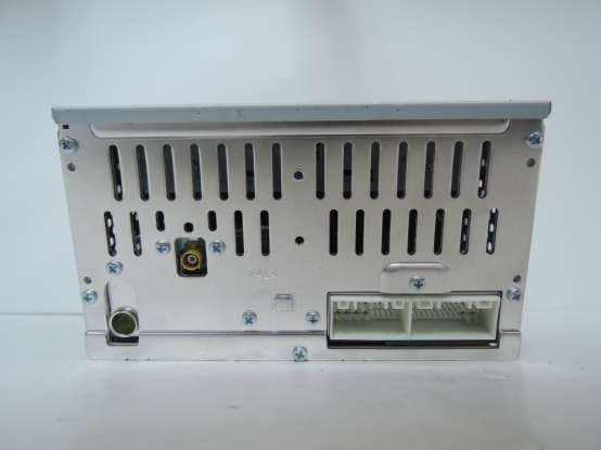
Click to zoom
Application Details
- Equipment Class
- DSS - Part 15 Spread Spectrum Transmitter
- Date of Grant
- Apr 21, 2014
- Application Purpose
- Original Equipment
- Date of Application
- Apr 21, 2014
- Equipment Note
- DIGITAL CAR AUDIO SYSTEM
- Frequency Range
- 2402.00000000 - 2480.00000000
- Company
- HYUNDAI MOBIS CO., LTD.
- Country
- South Korea
Documents & Files
Document Text
Text extracted from the exhibit documents filed with the FCC. Open a document above to read the original.
Users Manual
41 Features of your vehicle How vehicle audio works AM and FM radio signals are broad- cast from transmitter towers located around your city. They are intercept- ed by the radio antenna on your vehi- cle. This signal is then received by the radio and sent to your vehicle speakers. When a strong radio signal has reached your vehicle, the precise engineering of your audio system ensures the best possible quality reproduction. However, in some cases the signal coming to your vehi- cle may not be strong and clear. This can be due to factors, such as the distance from the radio station, closeness of other strong radio sta- tions or the presence of buildings, bridges or other large obstructions in the area. AM broadcasts can be received at greater distances than FM broad- casts. This is because AM radio waves are transmitted at low fre- quencies. These long, low frequency radio waves can follow the curvature of the earth rather than travelling straight out into the atmosphere. In addition, they curve around obstruc- tions so that they can provide better signal coverage. ¢¢¢ JBM001 ¢¢¢¢¢¢ JBM002 FM reception AM (MW, LW) reception Features of your vehicle 24 FM broadcasts are transmitted at high frequencies and do not bend to follow the earth's surface. Because of this, FM broadcasts generally begin to fade at short distances from the station. Also, FM signals are eas- ily affected by buildings, mountains, or other obstructions. These can result in certain listening conditions which might lead you to believe a problem exists with your radio. The following conditions are normal and do not indicate radio trouble: • Fading - As your vehicle moves away from the radio station, the signal will weaken and sound will begin to fade. When this occurs, we suggest that you select another stronger station. • Flutter/Static - Weak FM signals or large obstructions between the transmitter and your radio can dis- turb the signal causing static or fluttering noises to occur. Reducing the treble level may lessen this effect until the disturbance clears. • Station Swapping - As a FM signal weakens, another more powerful signal near the same frequency may begin to play. This is because your radio is designed to lock onto the clearest signal. If this occurs, select another station with a stronger signal. • Multi-Path Cancellation - Radio signals being received from sever- al directions can cause distortion or fluttering. This can be caused by a direct and reflected signal from the same station, or by signals from two stations with close fre- quencies. If this occurs, select another station until the condition has passed. ¢¢¢ JBM004JBM005JBM003 FM radio station 43 Features of your vehicle Using a cellular phone or a two- way radio When a cellular phone is used inside the vehicle, noise may be produced from the audio system. This does not mean that something is wrong with the audio equipment. In such a case, use the cellular phone at a place as far as possible from the audio equip- ment. Caring for disc • If the temperature inside the car is too high, open the car windows to ventilate before using the system. • It is illegal to copy and use MP3/WMA files without permis- sion. Use CDs that are created only by lawful means. • Do not apply volatile agents, such as benzene and thinner, normal cleaners and magnetic sprays made for analogue disc onto CDs. • To prevent the disc surface from getting damaged, hold CDs by the edges or the center hole only. • Clean the disc surface with a piece of soft cloth before playback (wipe it from the center to the outside edge). • Do not damage the disc surface or attach pieces of sticky tape or paper. • Make certain only CDs are insert- ed into the CD player (Do not insert more than one CD at a time). • Keep CDs in their cases after use to protect them from scratches or dirt. CAUTION When using a communication system such as a cellular phone or a radio set inside the vehicle, a separate external antenna must be fitted. When a cellular phone or a radio set is used with an internal antenna alone, it may interfere with the vehi- cle's electrical system and adversely affect safe operation of the vehicle. WARNING Do not use a cellular phone while driving. Stop at a safe location to use a cellular phone. Features of your vehicle 44 • Depending on the type of CD- R/CD-RW CDs, certain CDs may not operate normally according to manufacturing companies or mak- ing and recording methods. In such circumstances, continued use may cause malfunctions to your audio system. ✽NOTICE - Playing an Incompatible Copy Protected Audio CD Some copy protected CDs, which do not comply with international audio CD standards (Red Book), may not play on your car audio. Please note that inabilities to properly play a copy protected CD may indicate that the CD is defective, not the CD player. NOTE: Order of playing files (folders) : 1. Song playing order :to sequentially. 2. Folder playing order : ❋If no song file is contained in the folder, that folder is not dis- played. 45 Features of your vehicle CAUTION • Operating the device while driving could lead to acci- dents due to a lack of atten- tion to external surroundings. First park the vehicle before operating the device. • Adjust the volume to levels that allow the driver to hear sounds from outside of the vehicle. Driving in a state where external sounds cannot be heard may lead to acci- dents. • Pay attention to the volume setting when turning the device on. A sudden output of extreme volume upon turning the device on could lead to hearing impairment. (Adjust the volume to a suitable levels before turning off the device.) (Continued) WARNING • Do not stare at the screen while driving. Staring at the screen for prolonged periods of time could lead to traffic accidents. • Do not disassemble, assem- ble, or modify the audio sys- tem. Such acts could result in accidents, fire, or electric shock. • Using the phone while driving may lead to a lack of attention of traffic…
Text truncated - open the document above for the full version.
Cover Letter(s)
HYUNDAI MOBIS Co., Ltd. 203 Teheran-ro, Gangnam-gu, Seoul, Korea, 135-977 Date : April 16, 2014 Letter of Authorization We, the undersigned, hereby authorize Harvey Sung of Digital EMC Co., Ltd. to act on our behalf in all manners relating to application for equipment authorization for FCCID: TQ8-AM1A0C6AN including signing of all documents relating to these matters. Any and all acts carried out by Harvey Sung of Digital EMC Co., Ltd. on our behalf shall have the same a ffect as acts of our own. This authorization is valid until further written notice from HYUNDAI MOBIS Co., Ltd. “I, the undersigned, hereby certify that we are not subject to a denial of federal benefits, that includes FCC benefits, pursuant to Section 5301 of the Anti-Drug Abuse Act of 1988, 21 U.S.C. 853(a).” Sincerely, Seung Hoon Choe Manager
Cover Letter(s)
Digital EMC Co., Ltd. 42, Yurim-ro, 154beon-gil, Cheoin-gu, Yongin-si, Gyeonggi-do, Korea 449-935 Date: April 16, 2014 Compliance Certification Services Certification Division 47173 Benicia Street Fremont, CA 94538, USA To whom it may concern: I, the undersigned, hereby authorize Ms. Claire Hoque/Application Examiner of Compliance Engineering Services, Inc., d.b.a. Compliance Certification Services and hereafter referred to as CCS, to act on our behalf in all manners relating to application for equipment authorization, including signing of all documents relating to these matters. Any and all acts carried out by Ms. Claire Hoque of CCS on our behalf shall have the same effect as acts of our own. In authorizing CCS as our agent, we still recognize that we are responsible to: a) comply with the relevant provisions of the certification program; b) make all necessary arrangements for the conduct of the evaluation, including provision for examining documentation and access to all areas, records (including internal audit reports) and personnel for the purposes of evaluation (e.g. testing, inspection, assessment, surveillance, reassessment) and resolution of complaints; c) make claims regarding certification only in respect of the scope for which certification has been granted; d) do not use our product certification in such a manner as to bring the Certification Division into disrepute and not make any statement regarding our product certification which the Certification Division may consider misleading or unauthorized; e) upon suspension or cancellation of certification, discontinue use of all advertising matter that contains any reference thereto and return any certification documents as required by the Certification Division; f) use certification only to indicate the products are certified as being in conformity with specified standards;
Cover Letter(s)
HYUNDAI MOBIS Co., Ltd. 203 Teheran-ro, Gangnam-gu, Seoul, Korea, 135-977 Date: April 16, 2014 Compliance Certification Services Certification Division 47173 Benicia Street Fremont, CA 94538, USA RE: Request of Confidentiality for FCCID: TQ8-AM1A0C6AN To Whom It may Concern: Pursuant to Sections 0.457 and 0.459 of the Commission`s Rules(CFR 47), and Section 552 (b) (4) of the Freedom of Information Act, HYUNDAI MOBIS Co., Ltd. hereby requests confidentiality and treatment of certain information accompanying this application. The materials contain trade secrets and proprietary information not customarily released to the public. The public disclosure of these matters might be harmful to the Applicant and provide unjustified benefits to its competitors. We are also hereby request Short-Term Confidentiality for 180 days after the grant as outlined in Public Notice DA 04-1705. This provision will give HYUNDAI MOBIS Co., Ltd. temporary confidentiality of commercially sensitive information prior to product release. The requested permanent and Short-Term Confidential exhibits are listed as follows: PERMANENT & SHORT-TERM CONFIDENTIAL LIST Exhibit Description PERMANENT 1 Block Diagram 2 Schematics 3 Part Lists 4 Operation Description SHORT-TERM 5 Internal Photos 6 External Photos 7 Test-Setup Photos 8 User Manual The Applicant understands that pursuant to Rule 0.457, disclosure of this application and all accompanying documentations, where applicable, will not be public before the date of the Grant for this application. Sincerely, Seung Hoon Choe Manager
External Photos
FCCID: TQ8-AM1A0C6AN Copyright Ⓒ 2014, Digital EMC Co., Ltd. Page 1 / 3 View 1 FCCID: TQ8-AM1A0C6AN Copyright Ⓒ 2014, Digital EMC Co., Ltd. Page 2 / 3 View 2 FCCID: TQ8-AM1A0C6AN Copyright Ⓒ 2014, Digital EMC Co., Ltd. Page 3 / 3 View 3
ID Label/Location Info
FCC ID: TQ8-AM1A0C6AN Copyright Ⓒ 2014, Digital EMC Co., Ltd. SAMPLE LABEL & LOCATION LABELLING REQUIREMENTS The Label shown shall be permanently affixed at a conspicuous location on the device and be readily visible to the user at the time of purchase Label locate Top side This device complies with Part 15 of the FCC Rules. Operation is subject to the following two conditions: 1) This device may not cause harmful interference, and 2) This device must accept any interference received, including interference that may cause undesired operation of the device. - The FCC label shown is representative of the label that will appear on the radio when in production. Other information may also be included on this label.
Internal Photos
FCCID: TQ8-AM1A0C6AN Copyright Ⓒ 2014, Digital EMC Co., Ltd. View 1 FCCID: TQ8-AM1A0C6AN Copyright Ⓒ 2014, Digital EMC Co., Ltd. View 2 FCCID: TQ8-AM1A0C6AN Copyright Ⓒ 2014, Digital EMC Co., Ltd. View 3 FCCID: TQ8-AM1A0C6AN Copyright Ⓒ 2014, Digital EMC Co., Ltd. View 4 FCCID: TQ8-AM1A0C6AN Copyright Ⓒ 2014, Digital EMC Co., Ltd. View 5 FCCID: TQ8-AM1A0C6AN Copyright Ⓒ 2014, Digital EMC Co., Ltd. View 6 FCCID: TQ8-AM1A0C6AN Copyright Ⓒ 2014, Digital EMC Co., Ltd. View 7 FCCID: TQ8-AM1A0C6AN Copyright Ⓒ 2014, Digital EMC Co., Ltd. View 8 FCCID: TQ8-AM1A0C6AN Copyright Ⓒ 2014, Digital EMC Co., Ltd. View 9 FCCID: TQ8-AM1A0C6AN Copyright Ⓒ 2014, Digital EMC Co., Ltd. View 10 FCCID: TQ8-AM1A0C6AN Copyright Ⓒ 2014, Digital EMC Co., Ltd. View 11 FCCID: TQ8-AM1A0C6AN Copyright Ⓒ 2014, Digital EMC Co., Ltd. View 12 <Antenna>
RF Exposure Info
-~ - - ± &dBm ) - - The MPE calculation for this exposure is shown below. ▪=+- =+ == - ▪S=- = = MHz MPE Calculations : (Bluetooth) HYUNDAI MOBIS Co., Ltd. FCCID: TQ8-AM1A0C6AN Frequency range : 2402 MHz2480 dBm Min. Measured RF output power :dBm Target Power & Tolerance :dBm 2.19 1.001.5-0.5 Maximum antenna peak gain :dBi Maximum output power for the calculation : 2.50 dBm dB ( Max. 3.50 2.5 The EUT will only be used with a separation of 20 centimeters or greater between the antenna and the body of the EIRPPGNote 2.50 dBm3.50 dBiP = Power input to the antenna(dBm) 6.00 dBm3.982 mWG = Power gain of the antenna(dBi) Power density at the specific separation EIRP / ( 4 R 2 π ) Note 3.982 / ( 4 X 20 2 X π )S = Maximum power dencity(mW/cm 2 ) The maximum permissible exposure(MPE) of the general population/Uncontrolled for this device is 1.0 mW/cm 2 . 0.000793 mW/cm 2 EIRP = Equivalent Isotropic Radiated Power(mW) R = Distance to the center of the radiation of the antenna(20cm) Conclusion : The exposure condition of this device is compliant with FCC rules. TRF-RF-206(01)140415
Test Report
FCCID: TQ8-AM1A0C6AN DEMC1404-01195 Report No.: DRTFCC1404-0488 TRF-RF-212(02)140314 Page 2 / 71 Copyright ○ C 2014, Digital EMC Co., Ltd. Test Report Version Test Report No. Date Description DRTFCC1404-0488 Apr. 17, 2014 Initial issue FCCID: TQ8-AM1A0C6AN DEMC1404-01195 Report No.: DRTFCC1404-0488 TRF-RF-212(02)140314 Page 3 / 71 Copyright ○ C 2014, Digital EMC Co., Ltd. Table of Contents 1.General Information ................................................................................................................ 5 1.1. Testing Laboratory .......................................................................................... 5 1.2. Details of Applicant ......................................................................................... 5 1.3. Description of EUT .......................................................................................... 5 1.4. Declaration by the manufacturer .................................................................... 5 1.5. Information about the FHSS characteristics: ................................................ 6 1.6. Test Equipment List ........................................................................................ 7 1.7. Summary of Test Results ................................................................................ 8 1.8 Conclusion of worst-case and operation mode .............................................. 9 2. Transmitter Radiated Spurious Emissions and Conducted Spurious Emission .......... 10 2.1. Test Setup ...................................................................................................... 10 2.2. Limit ................................................................................................................ 10 2.3. Test Procedures............................................................................................. 11 2.3.1. Test Procedures for Radiated Spurious Emissions................................ 11 2.3.2. Test Procedures for Conducted Spurious Emissions ............................ 11 2.4. Test Results ................................................................................................... 12 2.4.1. Radiated Emission .................................................................................... 12 2.4.2. Conducted Spurious Emissions .............................................................. 15 3. Carrier Frequency Separation............................................................................................. 39 3.1.Test Setup ..................................................................................................... 39 3.2. Limit .............................................................................................................. 39 4. Number of Hopping Frequencies ....................................................................................... 44 4.1. Test Setup..................................................................................................... 44 4.2. Limit .............................................................................................................. 44 5. 20dBc BW .............................................................................................................................. 50 5.1. Test Setup..................................................................................................... 50 5.2. Limit .............................................................................................................. 50 5.3. Test Procedure ............................................................................................. 50 5.4. Test Results .................................................................................................. 50 6. Time of Occupancy (Dwell Time) ........................................................................................ 56 6.1. Test Setup..................................................................................................... 56 6.2. Limit .............................................................................................................. 56 6.3. Test Procedure ............................................................................................. 56 6.4. Test Results .................................................................................................. 56 7. Maximum Peak Output Power Measurement .................................................................... 61 7.1. Test Setup..................................................................................................... 61 7.2. Limit .............................................................................................................. 61 7.3. Test Procedure ............................................................................................. 61 7.4. Test Results .................................................................................................. 62 8. Transmitter AC Power Line Conducted Emission ............................................................ 68 FCCID: TQ8-AM1A0C6AN DEMC1404-01195 Report No.: DRTFCC1404-0488 TRF-RF-212(02)140314 Page 4 / 71 Copyright ○ C 2014, Digital EMC Co., Ltd. 8.1. Test Setup..................................................................................................... 68 8.2. Limit .............................................................................................................. 68 8.3. Test Procedures ........................................................................................... 68 8.4. Test Results: N/A ......................................................................................... 68 9. Antenna Requirement .......................................................................................................... 69 10. Occupied Bandwidth(99%) ................................................................................................ 70 APPENDIX I ...............................................…
Text truncated - open the document above for the full version.
Test Setup Photos
FCC ID: TQ8-AM1A0C6AN Copyright Ⓒ 2014, Digital EMC Co., Ltd. Test Setup photographs EUT Position: X-axis FCC ID: TQ8-AM1A0C6AN Copyright Ⓒ 2014, Digital EMC Co., Ltd. Test Setup Photo of Radiated Measurement (0.009 ~ 30MHz) FCC ID: TQ8-AM1A0C6AN Copyright Ⓒ 2014, Digital EMC Co., Ltd. Test Setup Photo of Radiated Measurement (below 1000MHz) FCC ID: TQ8-AM1A0C6AN Copyright Ⓒ 2014, Digital EMC Co., Ltd. Test Setup Photo of Radiated Measurement (Above 1GHz)
Contact Information
Applicant
Seung Hoon Choe(Senior Engineer)
Test Firm
DT&C Co.,Changho Lee
Technical Specifications
| # | Rule Parts | Frequency Range | Power Output |
|---|---|---|---|
| 1 | 15C | 2.40 GHz - 2.48 GHz | 1.66 mW |
Other Applications from HYUNDAI MOBIS CO., LTD.
TQ8-FOB-4FC0M22
Sep 11, 2026FOB Smart Key
Equipment Class
DSC - Part 15 Security/Remote Control TransmitterTQ8-FOB-4FC0M44
Sep 10, 2026FOB Smart Key
Equipment Class
DSC - Part 15 Security/Remote Control TransmitterTQ8-FOB-4FC1U44
Jul 20, 2026FOB Smart Key
Equipment Class
DSC - Part 15 Security/Remote Control TransmitterTQ8-FOB-4FC1M44
Jul 08, 2026FOB Smart Key
Equipment Class
DSC - Part 15 Security/Remote Control TransmitterTQ8-FOB-4FC0U22
Jun 17, 2026FOB Smart Key
Equipment Class
DSC - Part 15 Security/Remote Control Transmitter