Text extracted from the exhibit documents filed with the FCC. Open a document above to read the original.
Phone 401.828.4000 • Fax 401.822.2430 • Technical Support 877.472.7779 • E-mail [email protected] Web site: www.grass-telefactor.com USERS MANUAL Manual Part Number M636K05 600 East Greenwich Avenue, West Warwick, RI 02893 AURA ® PSG GRASS-TELEFACTOR ® WITH AURAPSG AMPLIFIER SYSTEM WIRELESS /AMBULATORY RECORDER Release A © COPYRIGHT 2005ASTRO-MED, INC. This manual is copyrighted with all rights reserved. No part of this manual may be reproduced, transmitted, transcribed, stored in a retrieval system, or translated into any language in any form by any means without written permission of Grass-Telefactor, An Astro-Med, Inc. Product Group. Information in this document is subject to change without notice. Astro-Med, Inc. assumes no responsibility for any errors, omissions or inaccuracies whatsoever. The software described in this document is furnished under a software license agreement. The software may be used only in accordance with the terms of this agreement. Except as permitted by the software license agreement, no part of this software may be reproduced, transmitted, transcribed, stored in a retrieval system, or translated into any language, in any form or by any means, electronic, mechanical, magnetic, optical, chemical, or manual, including photocopying, anywhere in the world without the written permission of Astro-Med, Inc. TRADEMARKS AURA ® , Aurora ® , Beehive ® , Beehive Millennium ® , Brain Navigator ® , BrainTree ® , Comet ® , EZM ® , EC2 ® , FASS ™ , Gamma ® , GrassLab ® , Heritage ® , H2O ® , Panorama ® , PolyVIEW ® , SAFELEAD ® , SleepTrek ® , Sonoma ® , SzAC ® , TWin ® and TWinLOOK ® are trademarks of Astro-Med, Inc. CompactFlash ® is a trademark of SanDisk Corporation. Windows ® is a trademark of Microsoft Corporation. Bluetooth ™ is a trademark of Bluetooth SIG, Inc. PureLight ® is a trademark of Nonin Medical, Inc. Other brand and product names are trademarks or registered trademarks of their representative holders. Printed in the United States of America AMPLIFIER SYSTEM IDENTIFICATION DATA Congratulations. Your Grass-Telefactor purchase is an investment in the finest of state-of-the-art medical technology. The information provided below lists the model number and serial number of your Amplifier system. If, for any reason, it should be necessary for you to contact Astro–Med, Inc. regarding your purchase, please refer to the following: Amplifier Serial Number: ______________________ Base Station Serial Number:______________________ IMPORTANT This manual is subject to periodic review, update, and revision. Customers are cautioned to verify that the manual’s information applies to the software and hardware present in the equipment. This product performs as described in this manual, and in accompanying labels and/or inserts, when assembled, operated, maintained, and repaired in accordance with the instructions provided. This product must be cleaned and checked periodically. Do not use a defective product. Parts that are broken, missing, worn, or contaminated should be replaced immediately. If repair or replacement becomes necessary, call or write to request service advice from Grass-Telefactor. This product must not be altered without the prior written approval of Grass-Telefactor. The user of this product shall have the sole responsibility for any malfunction that results from improper use, faulty maintenance, improper repair, unauthorized service, or alteration by anyone other than Grass-Telefactor. The safety, reliability, and performance of this device can only be assured under the following conditions: •If the device has been used according to the accompanying operating instructions. •If changes or repairs have been carried out by Grass-Telefactor. •If it is used in buildings having ground equalization wiring that complies with relevant UL, CSA, IEC or other local standards and regulations. REGULATORY NOTICES This device has been designed and certified to comply with the requirements of the international standard EN60601-1 and EN60601-2-26, EN60601-1-2, and EN60601-1-1 the United States standard UL 60601-1, and the Canadian standard CAN/CSA22.2 No.601.1. The device is classified: CLASS I, Type BF 100-250 VAC, 50/60 Hz, 80 VA The above classification is based on the condition that this device is installed and configured according to the instructions supplied. In order for the complete system to maintain compliance with the relevant standards, the host computer must be approved to the IEC950 standard. This equipment has been tested and found to comply with the limits for a Class B digital device, pursuant to part 15 of the FCC Rules. These limits are designed to provide reasonable protection against harmful interference in a residential installation. This equipment generates, uses and can radiate radio frequency energy and, if not installed and used in accordance with the instructions, may cause harmful interference to radio communications. However, there is no guarantee that interference will not occur in a particular installation. If this equipment does cause harmful interference to radio or television reception, which can be determined by turning the equipment off and on, the user is encouraged to try to correct the interference by one or more of the following measures: •Reorient or relocate the receiving antenna. •Increase the separation between the equipment and receiver. •Connect the equipment into an outlet on a circuit different from that to which the receiver is connected. •Consult the dealer or an experienced radio/TV technician for help. This device complies with part 15 of the FCC Rules. Operation is subject to the following two conditions: 1. This device may not cause harmful interference, and 2. This device must accept any interference received, including interference that may cause undesired operation. EQUIPMENT CLASSIFICATIONS Shock Prevention: Class 1 Degree of Protection Against Harmful Ingress of Water: Ordinary Equipment, IPX0 Degree of Sa…
Text truncated - open the document above for the full version.
Attention: Application Examiner Reviewing Engineer Re: Request for confidentiality per Section 0.459 of FCC Rules Applicant: Astro-Med, Inc. FCC ID: TQC-PSGBASE To whom it may concern, Request is hereby submitted by Astro-Med, Inc., to withhold from public review certain portions of the application for equipment certification for the referenced FCC identifier. In particular, the following sections of the application and report are requested to be kept confidential: ∑ Schematics ∑ Detailed Block diagrams ∑ Detailed Operational/Functional Description Rationale for request for confidentiality: Astro-Med, Inc. wishes to keep these items confidential to maintain a competitive advantage in the marketplace. The $145 fee for confidentiality has been submitted along with the fee for certification. If you have questions or need further information, please contact the undersigned. Sincerely, Date: Dec 7, 2005 Peter J. Fournier Senior Engineer
B 1 234 5 REVISIONS LETTER DESCRIPTION DATE OF CHANGE DATE OF APPROVAL 600 East Greenwich Ave, West Warwick, RI 02893 (401) 828-4000 REV SIZECLASS SCALE USED ON AURA PSG BASE FINISH MATERIAL SEE ABOVE ISS APP ENG CHK DWN REMOVE BURRS AND SHARP EDGES ALL SURFACES 63 UNLESS OTHERWISE SPECIFIED DIMENSIONS ARE IN INCHES TOLERANCES: DECIMAL .XX .01 DECIMAL .XXX .005 FRACTIONAL 1/64 ANGULAR 2 INITIALSDATE HLB-21930 SHEET 1 LABEL FCC/IC AURA PSG BASE BS10/27/05 C D A A B C D 678 87 6542 HLB-21930 3 1 OF 1 A GRASS-TELEFACTOR 1.) UNLESS NOTED, ALL TEXT IS ARIAL 9pt 2.) MATERIAL : 33501-113 3.) RIBBON : RY SCALE 1:1 SCALE 2:1 2” 1” Arial 9pt BOLD Model :AURA-PSG BASE FCC ID :TQC-PSGBASE IC :6176A-PSGBASE Serial : Model :AURA-PSG BASE FCC ID :TQC-PSGBASE IC :6176A-PSGBASE Serial :
H E G C B A F D 8 7 6 5 2 4 1 3 F A B C G E D H 1 3 4 2 5 6 7 8 REVDESCRIPTIONISSUER ECO # DATE 600 East Greenwich Ave, West Warwick, RI 02893 (401) 828-4000 Material: Finish: Class -- used on AURA PSG BASE STATION E 42145-000 REV 1 : 1 scale Sheet 1 of 2 PROPRIETARY INFORMATION: THIS DRAWING AND ALL INFORMATION CONTAINED WITHIN IS THE SOLE PROPERTY OF ASTRO-MED, INC., AND SHALL NOT BE REPRODUCED, COPIED, OR DISCLOSED WITHOUT THE WRITTEN PERMISSION OF ASTRO-MED, INC. Dimensions: inches. Remove burrs and break edges. Tolerances: .XX .01; .XXX .005; X/X 1/64; X2 Surfaces: 63 DWN: CHK: ENG: APP: ISS: INITIALSDATE D SIZE JPC 10/28/05 B NO CHANGES THIS SHEET 4345 5/23/05 C NO CHANGES THIS SHEET 4353 CZB JPC 5/27/05 D 7/18/05 JPC 4902 NO CHANGES THIS SHEET E 10/28/05 JPC 5074 NEW LABELS AND LABEL NOTES ADDED 2.61 GRASS-TELEFACTOR LOGO 7.50 7.00 #6-32 UNC-2B .156 (4) PLCS AFFIX LABELS AS SHOWN HLB-21836 HLB-21930 1.675 1.184 LEMO NUT AND DC INPUT JACK HEX NUT MUST BE TIGHTENED AT FINAL ASSEMBLY H E G C B A F D 8 7 6 5 2 4 1 3 F A B C G E D H 1 3 4 2 5 6 7 8 REVDESCRIPTIONISSUER ECO # DATE 600 East Greenwich Ave, West Warwick, RI 02893 (401) 828-4000 Material: Finish: Class -- used on AURA PSG BASE STATION E 42145-000 REV 2 : 3 scale Sheet 2 of 2 PROPRIETARY INFORMATION: THIS DRAWING AND ALL INFORMATION CONTAINED WITHIN IS THE SOLE PROPERTY OF ASTRO-MED, INC., AND SHALL NOT BE REPRODUCED, COPIED, OR DISCLOSED WITHOUT THE WRITTEN PERMISSION OF ASTRO-MED, INC. Dimensions: inches. Remove burrs and break edges. Tolerances: .XX .01; .XXX .005; X/X 1/64; X2 Surfaces: 63 DWN: CHK: ENG: APP: ISS: INITIALSDATE D SIZE JPC 10/28/05 B 5/23/05JPC 4345 LEMO CONNECTOR HARNESS NOTES ADDED C GROUND HARNESS TERMINAL & THREAD FORMING SCREWS ADDED 4353 CZB 5/27/05 D 7/18/05 JPC 4902 DC INPUT HEX NUT AND LEMO NUT ASSEMBLY NOTES ADDED E NO CHANGES THIS SHEET 5074 JPC 10/28/05 COMPLETE ASSEMBLY SCALE 1:1 THESE VIEWS ONLY 4 x 14236-442 4 x 10649-002 4 x 10650-002 4 x 10640-004 4 x 10650-004 26959-100 42712-01X 8 x 10608-006 5 x 26617-000 7 x 14347-620 14370-000 32719-275 26641-10X 42711-11X 26615-000 42809-001 INSTALL THESE (7) SCREWS AS THE FINAL STEP 20312-112 4 x 10612-024 4 x 10643-002 4 x 10644-002 10786-000 10650-004
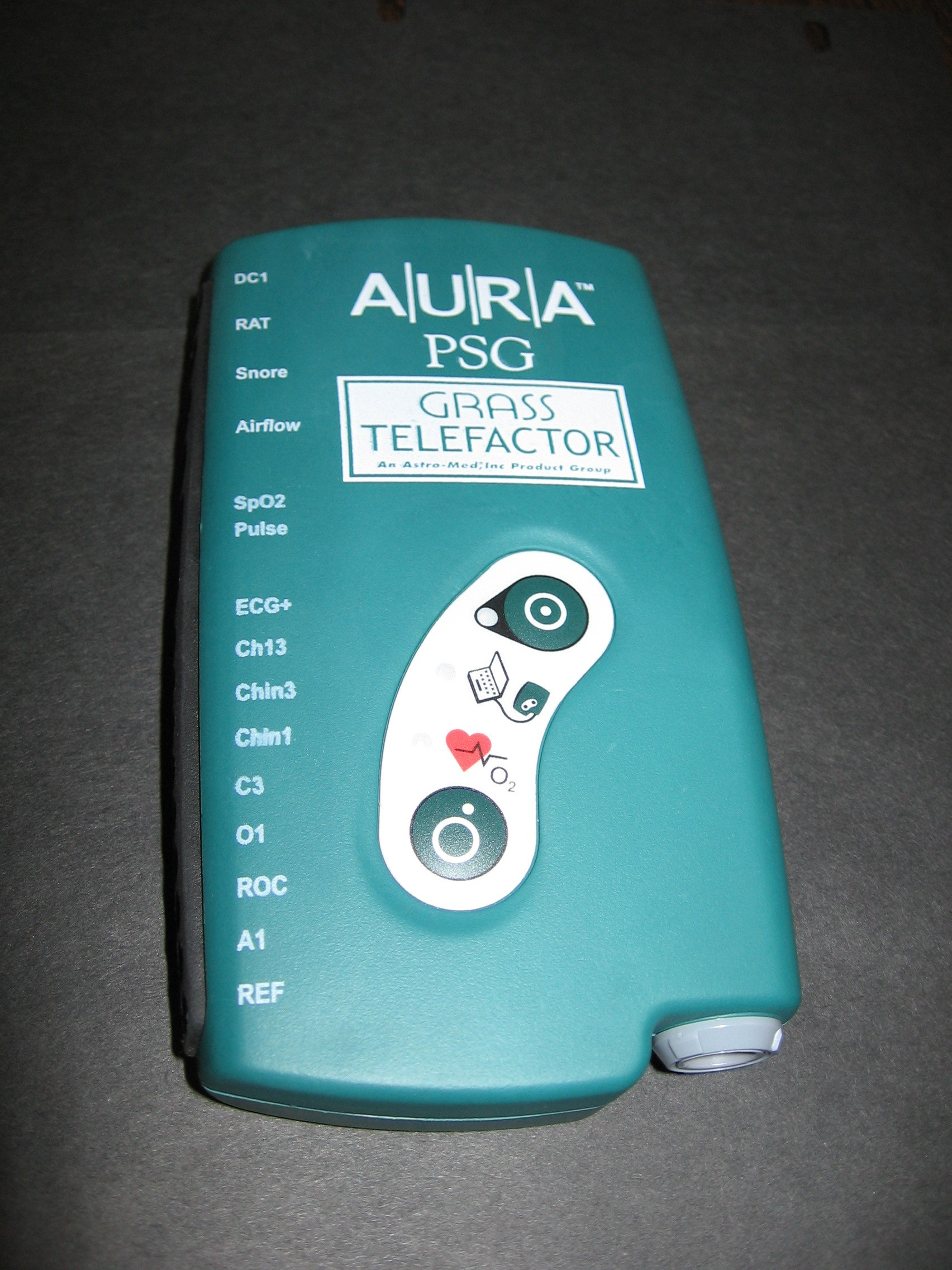
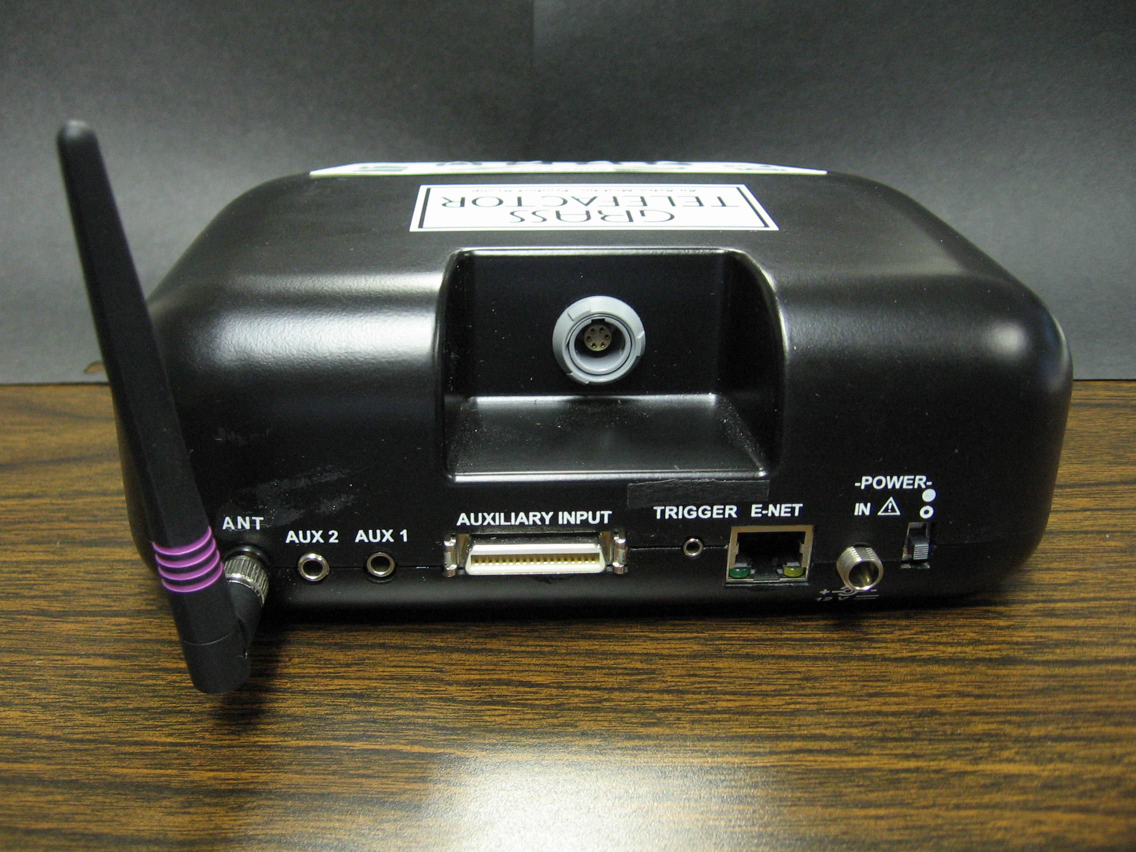
Aura-PSG System Operational Description The AURA PSG amplifier system is intended for recording routine electroencephalography (EEG) and polysomnography (PSG). The device is intended to be used only by physicians, technicians, or other medical professionals that are trained in electroencephalography or polysomnography. The system features a compact, wearable 24-channel Amplifier Unit and a Base Station that can be mounted in a variety of locations. The Amplifier Unit digitizes the signals of interest and transmits them to a Base Station which adds any further information required and passes the data to the end user’s computer via Ethernet. The wireless mode allows ambulatory applications within 25 feet (without obstructions) of the Base Station. The Amplifier and Base make use of the National Semiconductor LMX9820A Bluetooth Module (FCCID: ED9LMX9820ASM) for wireless connections. The Amplifier uses an SMD antenna which is not accessible to the user. The Base uses an external swivel SMA antenna.
Emissions Report for Astro-Med, Inc. on the AURA-PSG Base Station and Amplifier, Model AURA- PSG Report Number 3078319BOX.017a Page 2 of 29 1.0 Job Description 1.1 Client Information This EUT has been tested at the request of Company: Astro-Med, Inc. 600 East Greenwich Avenue West Warwick, RI 02893 Contact: Michael Sullivan Telephone: Fax: 401-828-4000 401-822-2430 1.2 Equipment Under Test Equipment Type: EEG Amplifier with Wireless Mode Model Number(s): AURA-PSG Serial number(s): #3 & #4, and #5 & #5 Manufacturer: Astro-Med, Inc. EUT receive date: 06/24/2005 EUT received condition: Good Test start date: 06/24/2005 Test end date: 10/18/2005 1.3 Test Plan Reference: Tested according to the standards listed and ANSI C63.4:2003 1.4 Test Configuration 1.4.1 Block Diagram Laptop Aura PSG Aura PSG Base Station P/S Aux Function Generator Power Cable Simulator Cable Turntable Ethernet Cable (to base station) Ethernet Cable (to laptop) AC Cable Event Cable SPO2 Cable Remote Location Emissions Report for Astro-Med, Inc. on the AURA-PSG Base Station and Amplifier, Model AURA- PSG Report Number 3078319BOX.017a Page 3 of 29 1.4.2 Cable List: Cable Shielding Connector Length (m) Qty. Event Cable Braid Metal Jack 3.0 1 Auxiliary Cable Braid Metal/360 2.0 1 AC Mains Cable None Plastic 3.0 1 Power Supply Cable None Metal Jack 2.0 1 Ethernet Cable Foil RJ45 with Metal Shield Grounds 5.0 1 Tether Cable None Plastic 3.0 1 SPO2 Cable None Plastic 1 1 Simulator Cable None Plastic 0.75 1 1.4.3 Support Equipment: Name: Model No.: Serial No.: Sony Laptop PCG-955A 283183303623910 Name: Model No.: Serial No.: Medi Cal Function Generator 220 904 Name: Model No.: Serial No.: Grass Telefactor Power Supply RPSAS40 04A0696G Name: Model No.: Serial No.: Auxiliary DC Input Module DCM8 03B0565G 1.5 Mode of Operation: The AURA-PSG Base Station was activated from nominal AC power (120V/60Hz) and the AURA-PSG was activated from a fresh battery. A function generator was used to provide simulated EEG signals to the AURA-PSG. The AURA-PSG transmitted the amplified EEG signals to the AURA-PSG Base Station wirelessly via a transmitter. Emissions Report for Astro-Med, Inc. on the AURA-PSG Base Station and Amplifier, Model AURA- PSG Report Number 3078319BOX.017a Page 4 of 29 2.0 Test Summary TEST STANDARD RESULTS FCC Part 15 Subpart C 15.247 SUB-TEST TEST PARAMETER COMMENT Occupied Bandwidth and Hopping Characteristics FCC 15.247(a)(1), (a)(1)(ii) The hopping characteristics must conform to the requirements of FCC 15.247(a)(1), (a)(1)(ii). The channel bandwidth is the 20 dB bandwidth. The channel separation must be greater than the 20dB bandwidth. The minimum number of hopping channels is 15. The maximum channel dwell time is 0.4 seconds over the period of 0.4 seconds multiplied by the number of hopping channels. Pass Transmitter Output Power and EIRP, and Human RF Exposure FCC 15.247(b)(1, 4-5) The output power must not exceed 1 Watt (30 dBm) and 36 dBm EIRP. The human RF Exposure limit is 1 mW/cm 2 . Pass Radiated Spurious Emissions FCC 15.205, 15.209, 15.247(d) The spurious emissions must be attenuated below the level of the fundamental by at least 20 dBc. Emissions which fall in the restricted bands must meet the general limits of 15.209. Pass Band Edge Compliance FCC 15.215 The fundamental frequency must stay within the assigned frequency band. Pass AC Line-Conducted Emissions FCC 15.207 The AC line-conducted emissions must not exceed the limits of 15.207. Pass The channels selected for test were channels 0, 39, and 78. Channel 0: 2402 MHz Channel 39: 2441 MHz Channel 78: 2480 MHz Emissions Report for Astro-Med, Inc. on the AURA-PSG Base Station and Amplifier, Model AURA- PSG Report Number 3078319BOX.017a Page 5 of 29 3.0 Sample Calculations The field strength is calculated by adding the Antenna Factor and Cable Factor, and subtracting the Amplifier Gain (if any) from the measured reading. The basic equation with a sample calculation is as follows: FS = RA + AF + CF - AG Where FS = Field Strength in dBμV/m RA = Receiver Amplitude (including preamplifier) in dBμV CF = Cable Attenuation Factor in dB AF = Antenna Factor in dB AG = Amplifier Gain in dB In the following table(s), the reading shown on the data table reflects the preamplifier gain. An example for the calculations in the following table is as follows. Assume a receiver reading of 52.0 dBμV is obtained. The antenna factor of 7.4 dB and cable factor of 1.6 dB is added. The amplifier gain of 29 dB is subtracted, giving a field strength of 32 dBμV/m. This value in dBμV/m was converted to its corresponding level in μV/m. RA = 52.0 dBμV AF = 7.4 dB/m CF = 1.6 dB AG = 29.0 dB FS = 32 dBμV/m Level in μV/m = [10( 32 dBμV/m)/20] = 39.8 μV/m The following is how net line-conducted readings were determined: NF = RF + LF + CF + AF Where NF = Net Reading in dBμV RF = Reading from receiver in dBμV LF = LISN Correction Factor in dB CF = Cable Correction Factor in dB AF = Attenuator Loss Factor in dB To convert from dBμV to μV or mV the following was used: UF = 10 (NF / 20) where UF = Net Reading in μV Example: NF = RF + LF + CF + AF = 28.5 + 0.2 + 0.4 + 20.0 = 49.1 dBμV UF = 10 (48.1 dBμV / 20) = 254 μV/m Emissions Report for Astro-Med, Inc. on the AURA-PSG Base Station and Amplifier, Model AURA- PSG Report Number 3078319BOX.017a Page 6 of 29 3.1 Measurement Uncertainty Compliance of the product is based on the measured value. However, the measurement uncertainty is included for informational purposes. The expanded uncertainty (k = 2) for radiated emissions from 30 to 1000 MHz has been determined to be: ±3.5 dB at 10m, ±3.8 dB at 3m The expanded uncertainty (k = 2) for mains conducted emissions from 150 kHz to 30 MHz has been determined to be: ±2.6 dB The expanded uncertainty (k = 2) for telecom port conducted emissions from 150 kHz to 30 MHz has been determined to be: ±3.2 for ISN and voltage probe measurements ±3.1 for current probe measurements Emissions Report for Astro-Med, Inc.…
Text truncated - open the document above for the full version.
Emissions Report for Astro-Med, Inc. on the AURA-PSG Base Station and Amplifier, Model AURA- PSG Report Number 3078319BOX.017a Page 21 of 29 Setup Photos Emissions Report for Astro-Med, Inc. on the AURA-PSG Base Station and Amplifier, Model AURA- PSG Report Number 3078319BOX.017a Page 22 of 29
600 East Greenwich Ave · West Warwick, Rhode Island · United States
| # | Rule Parts | Frequency Range | Power Output |
|---|---|---|---|
| 1 | 15C | 2.40 GHz - 2.48 GHz | 4.00 mW |

PSG Amp physiological signal recording
Equipment Class
DSS - Part 15 Spread Spectrum Transmitter