TQH13EATQHWireless motion detector system
Ultrec Engineered Products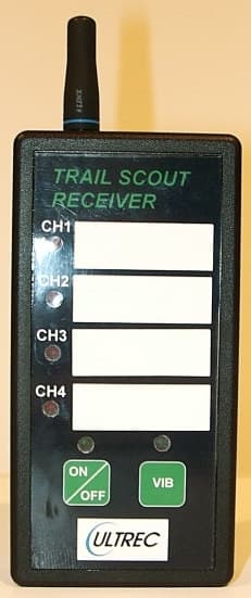
Click to zoom
Application Details
- Equipment Class
- DSR - Part 15 Remote Control/Security Device Transceiver
- Date of Grant
- Sep 18, 2006
- Application Purpose
- Original Equipment
- Date of Application
- Jun 20, 2006
- Equipment Note
- Wireless motion detector system
- Frequency Range
- 418.00000000 - 418.00000000
- Company
- Ultrec Engineered Products
- Country
- United States
Documents & Files
Document Text
Text extracted from the exhibit documents filed with the FCC. Open a document above to read the original.
Users Manual
Innovative products for the Outdoorsman TrailScout™ Operating Instructions Introduction The TrailScout sensor system is design to work with 1 to 4 sensors and 1 receiver. Each sensor can be set at a different channel, therefore providing sensing coverage of 4 different areas. Each sensor contains a PIR (pyroelectric infrared sensor). Infrared radiation exists in the electromagnetic spectrum at a wavelength that is longer than visible light. It cannot be seen but it can be detected. Objects that generate heat also generate infrared radiation and those objects include animals and the human body. Figure 1, Receiver Power & Vibrator switches Figure 2, Sensor power switch Receiver power switch ON OFF Vibrator power switch Quick start The TrailScout sensor system can be used indoors or outdoors. To conserve battery life, turn the receiver and sensor when not in use. Mount the sensors using the strap to a tree or post. (See sensor mounting and orientation) Close the external case and make sure the latches are secure. Turn the sensor power switch on, forward towards the front of the sensor, (see figure 2) and exit the area. Turn the receiver power switch on by pushing the power on/off button once. The green power on LED will illuminate indicating that the receiver power is on. Turn the receiver vibrator motor on by pushing the “VIB” button once. The green vibrator power on LED will illuminate indicating that the vibrate feature is turned on. Note that it is not necessary to turn on the vibrate feature for the receiver to operate properly. To turn off the receiver power or vibrate feature, push the corresponding button a second time. Sensor mounting and orientation Mount the sensors to a rigid support, such as a tree or post, using the strap provided. The sensor can also be mounted by using a small nail through the hole at the top of the mounting bracket. Aim the sensor at the desired subject area and then tighten the strap. The passive infrared motion sensor detects changes in heat within its coverage area. When a human or animal enters the sensor’s coverage area, it triggers the sensor, which sends a signal to the receiver to illuminate the appropriate LED and activate the vibrator motor, when the vibrator motor is turned on. The LED will be illuminated for approximately 18 seconds when the receiver unit receives a signal from the sensor. If the vibrator motor is turned on, the motor will run for approximately 4-5 seconds. The sensor is more sensitive to movement across its coverage zone and less sensitive to movement directly toward or away from the coverage zone. Therefore, choose a mounting location where the subject must walk across the coverage zone. When you choose the sensor mounting location, avoid a location where sunlight shines directly on the sensor. Setup Tips 1. When you choose the sensor mounting location, avoid a location where sunlight shines directly on the sensor. 2. Never attach the sensor to a tree or object that can move in the wind. Select a tree that is at least 7 inches or more in diameter. 3. Make sure that there are no branches or leaves blocking the view of the sensor. 4. When setting up your TrailScout system, bring along a spare 9VDC battery. This will allow you to swap the batteries if needed. 5. If you are using your system for bear hunting, make sure that you do not get any bait scent on the sensor housing. Otherwise, the bears will think that there is bait inside your sensor and destroy it trying to get inside. Sensor Control Settings Locate the 8 position dip switch inside the battery compartment of the sensor, see Figure 3. You must remove the battery to gain access to the dip switches. The default settings are switch 1 ON and all other switches turned off, as shown in Figure 3. Figure 3, SensorControl Settings dip switches Channel Operation Settings The channel selection is controlled using switch positions 1 thru 4 as follows. Channel 1 SW1 – ON SW2 – OFF SW3 – OFF SW4 – OFF Channel 2 SW1 – OFF SW2 – ON SW3 – OFF SW4 – OFF Channel 3 SW1 – OFF SW2 – OFF SW3 – ON SW4 – OFF Channel 4 SW1 – OFF SW2 – OFF SW3 – OFF SW4 – ON Walk Test LED (Red) The red test LED is controlled using switch position 5 as follows. LED on SW5 – ON LED off SW5– OFF PIR Sensitivity Adjustment The sensitivity adjustment allows you to easily set the PIR detecting sensitivity. The sensor is more sensitive in winter then in summer, be sure to reduce the sensitivity in summer by adjusting the sensitivity dip switches numbers 6-8, to avoid false triggering, see Figure 3. Sensitivity Level 1 (lowest) SW6 – OFF SW7 – OFF SW8 – OFF Sensitivity Level 2 SW6 – ON SW7 – OFF SW8 – OFF Sensitivity Level 3 SW6 – ON SW7 – ON SW8 – OFF Sensitivity Level 4 (highest) SW6 – ON SW7 – ON SW8 – ON Limited Warranty This product is warranted by Ultrec Engineered Products against manufacturing defects in material and workmanship, under normal use for 6 months from the date of purchase from Ultrec Engineered Products and authorized Ultrec Engineered Products dealers. In the event of a product defect during the warranty period, send the defective product along with a copy of you sales receipt to Ultrec Engineered Products, 860 Maple Ridge Lane, Brookfield WI, 53045. Ultrec Engineered Products at its option will (a) correct the defect by product repair without charge for parts and labor; (b) replace the product with one of a similar design. New or reconditioned parts and product may be used in the performance of the warranty service. Repaired or replaced parts and products are warranted for the remainder of the original warranty period. You will be charged for repair or replacement of the product made after the original warranty period. This warranty does not cover: (a) damage or failure caused by or attributable to acts of God, abuse, accident, misuse, improper or abnormal usage, failure to follow instructions, improper maintenance, bear attack, alteration, lightning or other incidence of excess voltage or current;…
Text truncated - open the document above for the full version.
Users Manual
Innovative products for the Outdoorsman TrailScout™ Operating Instructions Introduction The TrailScout sensor system is design to work with 1 to 4 sensors and 1 receiver. Each sensor can be set at a different channel, therefore providing sensing coverage of 4 different areas. Each sensor contains a PIR (pyroelectric infrared sensor). Infrared radiation exists in the electromagnetic spectrum at a wavelength that is longer than visible light. It cannot be seen but it can be detected. Objects that generate heat also generate infrared radiation and those objects include animals and the human body. Figure 1, Receiver Power & Vibrator switches Figure 2, Sensor power switch Receiver power switch ON OFF Vibrator power switch Quick start The TrailScout sensor system can be used indoors or outdoors. To conserve battery life, turn the receiver and sensor when not in use. Mount the sensors using the strap to a tree or post. (See sensor mounting and orientation) Close the external case and make sure the latches are secure. Turn the sensor power switch on, forward towards the front of the sensor, (see figure 2) and exit the area. Turn the receiver power switch on by pushing the power on/off button once. The green power on LED will illuminate indicating that the receiver power is on. Turn the receiver vibrator motor on by pushing the “VIB” button once. The green vibrator power on LED will illuminate indicating that the vibrate feature is turned on. Note that it is not necessary to turn on the vibrate feature for the receiver to operate properly. To turn off the receiver power or vibrate feature, push the corresponding button a second time. Sensor mounting and orientation Mount the sensors to a rigid support, such as a tree or post, using the strap provided. The sensor can also be mounted by using a small nail through the hole at the top of the mounting bracket. Aim the sensor at the desired subject area and then tighten the strap. The passive infrared motion sensor detects changes in heat within its coverage area. When a human or animal enters the sensor’s coverage area, it triggers the sensor, which sends a signal to the receiver to illuminate the appropriate LED and activate the vibrator motor, when the vibrator motor is turned on. The LED will be illuminated for approximately 18 seconds when the receiver unit receives a signal from the sensor. If the vibrator motor is turned on, the motor will run for approximately 4-5 seconds. The sensor is more sensitive to movement across its coverage zone and less sensitive to movement directly toward or away from the coverage zone. Therefore, choose a mounting location where the subject must walk across the coverage zone. When you choose the sensor mounting location, avoid a location where sunlight shines directly on the sensor. Setup Tips 1. When you choose the sensor mounting location, avoid a location where sunlight shines directly on the sensor. 2. Never attach the sensor to a tree or object that can move in the wind. Select a tree that is at least 7 inches or more in diameter. 3. Make sure that there are no branches or leaves blocking the view of the sensor. 4. When setting up your TrailScout system, bring along a spare 9VDC battery. This will allow you to swap the batteries if needed. 5. If you are using your system for bear hunting, make sure that you do not get any bait scent on the sensor housing. Otherwise, the bears will think that there is bait inside your sensor and destroy it trying to get inside. Sensor Control Settings Locate the 8 position dip switch inside the battery compartment of the sensor, see Figure 3. You must remove the battery to gain access to the dip switches. The default settings are switch 1 ON and all other switches turned off, as shown in Figure 3. Figure 3, SensorControl Settings dip switches Channel Operation Settings The channel selection is controlled using switch positions 1 thru 4 as follows. Channel 1 SW1 – ON SW2 – OFF SW3 – OFF SW4 – OFF Channel 2 SW1 – OFF SW2 – ON SW3 – OFF SW4 – OFF Channel 3 SW1 – OFF SW2 – OFF SW3 – ON SW4 – OFF Channel 4 SW1 – OFF SW2 – OFF SW3 – OFF SW4 – ON Walk Test LED (Red) The red test LED is controlled using switch position 5 as follows. LED on SW5 – ON LED off SW5– OFF PIR Sensitivity Adjustment The sensitivity adjustment allows you to easily set the PIR detecting sensitivity. The sensor is more sensitive in winter then in summer, be sure to reduce the sensitivity in summer by adjusting the sensitivity dip switches numbers 6-8, to avoid false triggering, see Figure 3. Sensitivity Level 1 (lowest) SW6 – OFF SW7 – OFF SW8 – OFF Sensitivity Level 2 SW6 – ON SW7 – OFF SW8 – OFF Sensitivity Level 3 SW6 – ON SW7 – ON SW8 – OFF Sensitivity Level 4 (highest) SW6 – ON SW7 – ON SW8 – ON Limited Warranty This product is warranted by Ultrec Engineered Products against manufacturing defects in material and workmanship, under normal use for 6 months from the date of purchase from Ultrec Engineered Products and authorized Ultrec Engineered Products dealers. In the event of a product defect during the warranty period, send the defective product along with a copy of you sales receipt to Ultrec Engineered Products, 860 Maple Ridge Lane, Brookfield WI, 53045. Ultrec Engineered Products at its option will (a) correct the defect by product repair without charge for parts and labor; (b) replace the product with one of a similar design. New or reconditioned parts and product may be used in the performance of the warranty service. Repaired or replaced parts and products are warranted for the remainder of the original warranty period. You will be charged for repair or replacement of the product made after the original warranty period. This warranty does not cover: (a) damage or failure caused by or attributable to acts of God, abuse, accident, misuse, improper or abnormal usage, failure to follow instructions, improper maintenance, bear attack, alteration, lightning or other incidence of excess voltage or current;…
Text truncated - open the document above for the full version.
Block Diagram
Block Diagram & Functional Description TrailScout sensor system Page 1 of 2 Block Diagram & Functional Description TrailScout sensor system Page 2 of 2 Operational Description The TrailScout sensor system consists of a wireless motion sensor and a wireless hand held receiver. Each sensor unit contains a PIR (pyroelectric infrared sensor) and a wireless transmitter that operates in the 418 MHz band. Infrared radiation exists in the electromagnetic spectrum at a wavelength that is longer than visible light. It cannot be seen, but it can be detected by the PIR sensor. When a human or animal enters the sensor’s coverage area, it triggers the sensor. The transmitter in the sensor unit is then activated and it transmits a signal to the receiver unit. When the receiver unit receives the signal it will illuminate a red LED for approximately 18 seconds, corresponding to the channel that the signal was received on. If the vibrator motor feature is turned on the receiver will also activate the vibrator motor for 4-5 seconds. The LED and vibrator motor will then turned off and the receiver unit will wait for the next transmission from a sensor unit. The receiver can monitor up to 4 of the sensor units by utilizing different channels.
External Photos
TrailScout External Photos Ultrec Engineered Products Figure 1, Receiver Outside Figure 2, Sensor/Transmitter Outside
Internal Photos
TrailScout Internal Photos Ultrec Engineered Products Figure 1, Receiver Inside Figure 2, Sensor/Transmitter Inside
Operational Description
Innovative products for the Outdoorsman TrailScout™ Operating Instructions Introduction The TrailScout sensor system is design to work with 1 to 4 sensors and 1 receiver. Each sensor can be set at a different channel, therefore providing sensing coverage of 4 different areas. Each sensor contains a PIR (pyroelectric infrared sensor). Infrared radiation exists in the electromagnetic spectrum at a wavelength that is longer than visible light. It cannot be seen but it can be detected. Objects that generate heat also generate infrared radiation and those objects include animals and the human body. Figure 1, Receiver Power & Vibrator switches Figure 2, Sensor power switch Quick start The TrailScout sensor system can be used indoors or outdoors. To conserve battery life, turn the receiver and sensor when not in use. Mount the sensors using the strap to a tree or post. (See sensor mounting and orientation) Close the external case and make sure the latches are secure. Turn the sensor power switch on, forward towards the front of the sensor, (see figure 2) and exit the area. Turn the receiver power switch on by pushing the power on/off button once. The green power on LED will illuminate indicating that the receiver power is on. Turn the receiver vibrator motor on by pushing the “VIB” button once. The green vibrator power on LED will illuminate indicating that the vibrate feature is turned on. Note that it is not necessary to turn on the vibrate feature for the receiver to operate properly. To turn off the receiver power or vibrate feature, push the corresponding button a second time. Sensor mounting and orientation Mount the sensors to a rigid support, such as a tree or post, using the strap provided. The sensor can also be mounted by using a small nail through the hole at the top of the mounting bracket. Aim the sensor at the desired subject area and then tighten the strap. The passive infrared motion sensor detects changes in heat within its coverage area. When a human or animal enters the sensor’s coverage area, it triggers the sensor, which sends a signal to the receiver to illuminate the appropriate LED and activate the vibrator motor, when the vibrator motor is turned on. The sensor is more sensitive to movement across its coverage zone and less sensitive to movement directly toward or away from the coverage zone. Therefore, choose a mounting location where the subject must walk across the coverage zone. When you choose the sensor mounting location, avoid a location where sunlight shines directly on the sensor. Setup Tips 1. When you choose the sensor mounting location, avoid a location where sunlight shines directly on the sensor. 2. Never attach the sensor to a tree or object that can move in the wind. Select a tree that is at least 7 inches or more in diameter. 3. Make sure that there are no branches or leaves blocking the view of the sensor. 4. When setting up your TrailScout system, bring along a spare 9VDC battery. This will allow you to swap the batteries if needed. 5. If you are using your system for bear hunting, make sure that you do not get any bait scent on the sensor housing. Otherwise, the bears will think that there is bait inside your sensor and destroy it trying to get inside. Sensor Control Settings Locate the 8 position dip switch inside the battery compartment of the sensor, see Figure 3. You must remove the battery to gain access to the dip switches. The default settings are switch 1 ON and all other switches turned off, as shown in Figure 3. Figure 3, SensorControl Settings dip switches Channel Operation Settings The channel selection is controlled using switch positions 1 thru 4 as follows. Channel 1 SW1 – ON SW2 – OFF SW3 – OFF SW4 – OFF Channel 2 SW1 – OFF SW2 – ON SW3 – OFF SW4 – OFF Channel 3 SW1 – OFF SW2 – OFF SW3 – ON SW4 – OFF Channel 4 SW1 – OFF SW2 – OFF SW3 – OFF SW4 – ON Walk Test LED (Red) The red test LED is controlled using switch position 5 as follows. LED on SW5 – ON LED off SW5– OFF PIR Sensitivity Adjustment The sensitivity adjustment allows you to easily set the PIR detecting sensitivity. The sensor is more sensitive in winter then in summer, be sure to reduce the sensitivity in summer by adjusting the sensitivity dip switches numbers 6-8, to avoid false triggering, see Figure 3. Sensitivity Level 1 (lowest) SW6 – OFF SW7 – OFF SW8 – OFF Sensitivity Level 2 SW6 – ON SW7 – OFF SW8 – OFF Sensitivity Level 3 SW6 – ON SW7 – ON SW8 – OFF Sensitivity Level 4 (highest) SW6 – ON SW7 – ON SW8 – ON Limited Warranty This product is warranted by Ultrec Engineered Products against manufacturing defects in material and workmanship, under normal use for 6 months from the date of purchase from Ultrec Engineered Products and authorized Ultrec Engineered Products dealers. In the event of a product defect during the warranty period, send the defective product along with a copy of you sales receipt to Ultrec Engineered Products, 860 Maple Ridge Lane, Brookfield WI, 53045. Ultrec Engineered Products at its option will (a) correct the defect by product repair without charge for parts and labor; (b) replace the product with one of a similar design. New or reconditioned parts and product may be used in the performance of the warranty service. Repaired or replaced parts and products are warranted for the remainder of the original warranty period. You will be charged for repair or replacement of the product made after the original warranty period. This warranty does not cover: (a) damage or failure caused by or attributable to acts of God, abuse, accident, misuse, improper or abnormal usage, failure to follow instructions, improper maintenance, bear attack, alteration, lightning or other incidence of excess voltage or current; (b) consumables such as batteries; (c) cosmetic damage; (d) costs for loss of use during the repair period. Company Contact Information Ultrec Engineered Products 860 Maple Ridge Lane Brookfield, WI 53045 (262) 821-0483, Fax: (262) 821-1156 Email: ult…
Text truncated - open the document above for the full version.
Parts List/Tune Up Info
Assembly Drawings TrailScout sensor system Page 1 of 6 Assembly Drawings TrailScout sensor system Page 2 of 6 Assembly Drawings TrailScout sensor system Page 3 of 6 Assembly Drawings TrailScout sensor system Page 4 of 6 Assembly Drawings TrailScout sensor system Page 5 of 6 Assembly Drawings TrailScout sensor system Page 6 of 6
Parts List/Tune Up Info
Parts List TrailScout sensor system Page 1 of 4 BILL OF MATERIAL (BOM) RECEIVER: Component Description Manufacturer Manuf. p/n Qty. Antenna 1/4-wave Antenna with RPSMA connection. Linx Tech. ANT-418-CW-QW or ANT-418-CW-RH 1 Antenna Connector RPSMA Female Edge Multi- Mount Linx Tech. CONREVSMA006.062 Battery Snap 9V battery Snap, 26 AWG, 6" leads Eagle 123-6006 1 Cap, 22uF, Tantalum C5,C7,C8,C9,C10; 10%, 16V, "B" Case AVX TAJB226K016R 5 Cap, 0.1uF, X7R C1,C4,C6,C11,C15,C16,C17, C18,C24; 10%, 50V, 0805 Kemet C0805C104K5RACTU 9 Cap, 2.2uF, Tantalum C19,C21,10%, 16V, "A" case Kemet T491A225K016AS 2 Cap, 4.7uF, Tantalum C2,C12,C20,C23; 10%, 16V, "B" Case Kemet T491B475K016AS 4 Cap, 100pF, NPO C3; 5%, 50V, 0805 Panasonic ECJ-2VC1H101J 1 Cap, .047uF, X7R C13; 10%, 50V, 1206 Xicom 140-CC502B473K 1 Cap, .022uF, X7R C14; 10%, 50V, 1206 Xicom 140-CC502B223K 1 LED (RED) D2,D5,D4,D10, Channel LED, T1 package Kingbright L934IT 4 DIODE D3,D6,D7,D8,D9,D11,D15,D 16,D17,D18,D19 Vishay LL4148 11 RECT D1, Power LED, T1 package MICROSEM1 1N4001MSCT 1 LED (GREEN) D13,D14, Power LED, T1 package Kingbright L934GT 2 1206 RES 15 R43 Xicon 263-15 1 1206 RES 100 R29,R31 Xicon 263-100 2 1206 RES 470K 1% R4,R11,R12,R13,R14,R26 Xicon 290-470K 4 1206 RES 47K R1,R39 Xicon 263-47K 2 1206 RES 390K R27 Xicon 263-390K 1 1206 RES 1K R3,R5,R6,R15 Xicon 263-1K 4 1206 RES 2.2K R35,R36 Xicon 263-2.2K 2 1206 RES 10K R25,R40 Xicon 263-10K 1 1206 RES 100K, 1% R24,R28,R38,R45 Xicon 290-100K 4 1206 RES 332K, 1% R2 Xicon 290-332K 1 1206 RES 20K R7,R8,R9,R10 Xicon 263-20K 4 1206 RES 1M R30,R32,R33,R34,R37,R41, R42,R44 Xicon 263-1M 8 RES Array, 100K RN1; 8TERM 4RES SMD (R20,R21,R22,R23) CTS Corp. 744C083104JTR 1 RES Array, 47K RN2; 8TERM 4RES SMD (R16,R17,R18,R19) CTS Corp. 744C083473JCT 1 220nH Inductor L1, 220nH Inductor, 0805 Panasonic ELJ-NDR22JF 1 Parts List TrailScout sensor system Page 2 of 4 56nH Inductor L2, 56nH Inductor, 0805 Bourns Inc. CI201210-56NJ 1 IC U1, 418.0 MHz Receiver RF Monolithics RX5002 1 IC U2, DECODER, 20 PIN SOP Holtek HT614 1 IC U3,NAND GATE, 14 PIN SOIC Fairchild Semi. CD4011BCM 1 IC U4, Voltage Regulator, 8- SOP Texas Instr. TPS76550D 1 IC U5, NAND W/SCHMITT INPUTS, 14 PIN SOIC Fairchild Semi. CD4093BCM 1 IC U6, Voltage Regulator, SOT- 23-5 Texas Instr. TPS77030DBVT 1 IC U7,U8; Flip Flop Dual, 14 Pin SOIC Fairchild Semi. CD4013BCM 2 Transistor Q6 PNP, SOT-23 Fairchild Semi. MMBT3906 1 Transistor Q1,Q2,Q3,Q4,Q5, NPN, SOT-23 STM Transistors MMBT3904 5 Transistor Q7, NPN, SOT-223 STM Transistors PZT3904 1 Header 3 pos. Rt. Angle header for keypad Molex 22-28-8030 1 Vib Motor Vibration motor Jinlong Mach. 6SH-0608B 1 PCB Receiver PCB bare board Imagineering, Inc.3001 1 Case Enclosure Hammond Manufacturing 1599BBKBAT 1 Keypad Keypad/overlay assembly Xymox Technologies, Inc.14904 1 screw #4 philips head, 1/4" long screw McMaster-Carr 90190A106 4 Legend Nameplate / FCC legend Brady Labels THT-6-423 1 SENSOR: Component Description Manufacture Manuf. P/N Qty. Antenna ANT1, LP Series, 1/4-wave whip Ant. Linx Tech. ANT-418-PW-LP 1 Battery Snap 9V battery Snap, 26 AWG, 6" leads Eagle 123-6006 1 Cap, 0.1uF, X7R C1,C3,C5,C9,C10,C11,C12; 10%, 50V, 0805 Kemet C0805C104K5RACTU 7 Cap, 22uF, Tantalum C2; 10%, 16V, "B" Case AVX TAJB226K016R 1 Cap, .01uF, X7R C15, 10%, 50V, 0805 Kemet C0805C103K5RACTU 1 Cap, 4.7 uF, Tantalum C16, C17; 10%, 16V, "B" Case Kemet T491B475K016AS 2 Cap, 1.0 uF, Tantalum C14; 10%, 16V, "A" Case Kemet T491A105K016AS 1 Cap, 10uF, Tantalum C4,C7,C8,C13; 10%, 16V, "B" Case Kemet T491B106K016AS 4 Cap, 100pF, NPO C6,C18,C19; 5%, 50V, 0805 Panasonic ECJ-2VC1H101J 3 RECT D7 MICROSEM1 1N4001MSCT 1 DIODE D2,D3,D4,D6 Vishay LL4148 4 Parts List TrailScout sensor system Page 3 of 4 Transistor Q1, NPN, SOT-23 Fairchild Semi. MMBT3904 1 1206 RES 1K R27 Panasonic ERJ-8GEYJ102V 1 1206 RES 2.2K R15 Panasonic ERJ-8GEYJ222V 1 1206 RES 28K R28 Panasonic ERJ-8GEYJ283V 1 1206 RES 10K R3, R9, R11 Panasonic ERJ-8GEYJ103V 3 1206 RES 47K R19, R25, R30, R31 Panasonic ERJ-8GEYJ473V 4 1206 RES 1M R2, R10, R12, R13, R16, R17, R22, R29 Panasonic ERJ-8GEYJ105V 8 1206 RES 4.7M R24 Panasonic ERJ-8GEYJ476V 1 1206 RES 100K R5 Panasonic ERJ-8GEYJ104V 1 1206 RES 180K R14 Panasonic ERJ-8GEYJ184V 1 1206 RES 200K R8 Panasonic ERJ-8GEYJ204V 1 1206 RES 680K R20 Panasonic ERJ-8GEYJ684V 1 1206 RES 470K, 1% R6,R18 Panasonic ERJ-8GEYJ474V 1 1206 RES 270K R23 Panasonic ERJ-8GEYJ274V 1 1206 RES 39K R21 Panasonic ERJ-8GEYJ393V 1 DIP SWITCH SW1, SPST 8 POS. DIP CTS Corp. 206-8RAST 1 TO-5 MOUNT MOUNT FOR U2 BIVAR 505-120 1 LED (yellow) D1, Low Battery LED, T1 3/4 package AGILENT Tech. HLMP-3401 1 LED (red) D5, Detector LED, T1 3/4 package AGILENT Tech. HLMP-3301 1 INDUCTOR L1, 220nH, 0805 Panasonic ELJ-NDR22JF 1 INDUCTOR L2, 56nH, 0805 Bourns Inc. CI201210-56NJ 1 INDUCTOR L3, 120 IMP. DCR, 1206 package Fair-Rite 2512061217YO 1 IC U1, 418Mhz Transmitter RF Monolithics TX5002 1 PIR Detector U2 Pyroelectric IR Detector Murata IRA-E710STO 1 IC U3, ENCODER, 20 pin SOP Holtek HT600 1 IC U4, DUAL OP AMP, 8 pin SO8 ST Micro. TS942AID 1 IC U5 DUAL COMPARATOR, 8 pin SOIC Linear Tech. LTC1441IS8 1 IC U6, Voltage Regulator, SOT- 23-5 TEXAS Instr. TPS77030DBVT 1 IC U7, Voltage Regulator, 8- SOP TEXAS Instr. TPS76550D 1 PCB Sensor PCB bare board Imagineering, Inc.3002 1 PIR Lens Fresnel lens Fresnel Technologies AA 1.2 GI V1 1 Case Enclosure, S-series Serpac Elec. Encl.231 1 Gasket Gasket for enclosure Serpac Elec. Encl.PS-13 1 Washer Nylon flat washer Micro Plastics, Inc. 17W02502 4 Power Switch SW2, SPST, TOGGLE, Panel Mounted Eswitch EG2358-ND 1 Switch Seal Black boot switch seal Alcoswitch 506-B14400 1 Parts List TrailScout sensor system Page 4 of 4 Bracket Mounting Bracket Engineered Metal Prod. 2015 1 Rivet Pop-rivet, 1/8" dia. X 1/4" grip McMaster-Carr 97519A025 2 Rivet backer washer, 1/8" O.D McMaster-Carr 90183A212 2 Screw #4 Philips pan head, 3/8" long screw McMaster-Carr 90190A108 8 legend Nameplate / FCC legend Brady Labels THT-6-423 1
Parts List/Tune Up Info
Assembly Drawings TrailScout sensor system Page 1 of 6 Assembly Drawings TrailScout sensor system Page 2 of 6 Assembly Drawings TrailScout sensor system Page 3 of 6 Assembly Drawings TrailScout sensor system Page 4 of 6 Assembly Drawings TrailScout sensor system Page 5 of 6 Assembly Drawings TrailScout sensor system Page 6 of 6
Schematics
trail_rec3.sch-1 - Tue Apr 22 08:06:37 2003
Schematics
sensor.sch-1 - Fri Apr 16 07:45:10 2004
Test Report
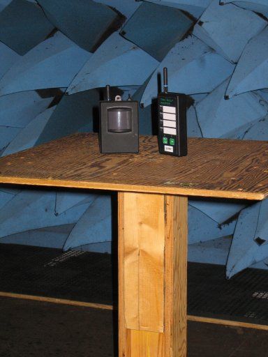
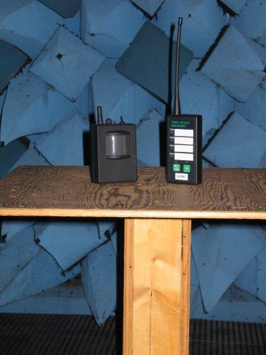
Indian Hill Hardware Compliance Test Laboratory Electromagnetic Compatibility Test Report Tested Product: TrailScout sensor system Type of Test: FCC Part 15, Subpart C, INTENTIONAL RADIATORS Indian Hill Hardware Compliance Laboratory Report No: IH-0306-01 TrailScout sensor system Page 1 of 19 CERTIFICATION OF REPORT This report has been prepared by the Indian Hill Global Hardware Compliance and Engineering Analysis Group to document compliance of the device described below to FCC Part 15, Subpart C, INTENTIONAL RADIATORS. This report may be reproduced in full, partial reproduction may only be made with written consent of the laboratory. The results in this report apply only to the sample tested. Applicant: Ultrec Engineered Products Manufacturer: Ultrec Engineered Products Model Name: TrailScout sensor system Model Numbers: TSS1 & TSR1 Test Engineer: Approving Manager: Phil Fair Test Start Date: Test End Date: March 06, 2006 March 14, 2006 Indian Hill Hardware Compliance Laboratory Report No: IH-0306-01 TrailScout sensor system Page 2 of 19 TABLE OF CONTENTS 1 CLIENT INFORMATION .........................................................................................................................3 1.1 Applicant: ............................................................................................................................................3 1.2 Manufacturer: ......................................................................................................................................3 1.3 Party Responsible for Declaration of Conformity:..............................................................................3 2 EQUIPMENT UNDER TEST (EUT).........................................................................................................4 2.1 Identification of EUT: .........................................................................................................................4 2.2 Description of EUT: ............................................................................................................................4 2.3 Modifications on EUT:........................................................................................................................4 3 TEST SPECIFICATION, METHODS AND PROCEDURES...................................................................5 3.1 Test Specification: ...............................................................................................................................5 3.2 Methods & Procedures: .......................................................................................................................5 3.2.1 Radiated emission limits, general requirements - Section 15.209................................................5 3.2.2 Periodic operation in the band, 40.66 - 40.70 MHz and above 70 MHz - Section 15.231. .........6 3.2.3 Test Procedure..............................................................................................................................8 4 OPERATION OF EUT DURING TESTING.............................................................................................9 4.1 Operating Environment: ......................................................................................................................9 4.2 Operating Modes: ................................................................................................................................9 4.3 Test Configuration:..............................................................................................................................9 4.4 Test Results .......................................................................................................................................10 4.4.1 Radiated emissions:.......................…
Text truncated - open the document above for the full version.
Contact Information
Applicant
John Kitscha
Technical Contact
Ultrec Engineered ProductsJohn J Kitscha
[email protected]262-821-0483
860 Maple Ridge Lane · Brookfield, Wisconsin · United States
Non-Technical Contact
Ultrec Engineered ProductsJohn J Kitscha
[email protected]262-821-0483
Test Firm
Alcatel-LucentNilesh Patel
Technical Specifications
| # | Rule Parts | Frequency Range | Power Output |
|---|---|---|---|
| 1 | 15.231 | 418 MHz - 418 MHz | - |