TQX-XSCAN440IISCANNING RECEIVER
KiMark International, Inc.
Click to zoom
Application Details
- Equipment Class
- CSR - Scanning Receiver
- Date of Grant
- Jan 24, 2007
- Application Purpose
- Original Equipment
- Date of Application
- Jan 24, 2007
- Equipment Note
- SCANNING RECEIVER
- Frequency Range
- 450.00000000 - 470.00000000
- Company
- KiMark International, Inc.
- Country
- United States
Documents & Files
Document Text
Text extracted from the exhibit documents filed with the FCC. Open a document above to read the original.
Users Manual
1 2 3FCC IMPORTANT NOTICE3 It is a federal crime to intentionally intercept cellular or cordless telephone transmissions. This scanner has been manufacture to lockout those frequencies assigned by the FCC for cellular telephone usage. Laws in your state may restrict or prohibit the use of scanning radios. Use of this radio in a motor vehicle may be prohibited, regulated, or require a permit. Check with state, city, and/or local jurisdictions prior to use. DECLARATION BY MANUFACTURER The Scanner receiver is not a digital scanner and is incapable of being converted or modified to a digital scanner receiver by any user. 3 3FCC IMPORTANT NOTICE 3 1. Changes or modifications to this device not expressly approved by Kimark International, Inc. could void the user’s authorization to operate this device. 2. This device complies with part 15 of the FCC Rules. Operation is subject to the following two conditions: (1) This device may not cause harmful interference, and (2) this device must accept any interference including received, interference that may cause undesired operation. 3. The scanning receiver in this equipment is incapable of tuning, or readily being altered, by the User to operate within the frequency bands allocated to the Domestic public Cellular Telecommunications Service in Part 22. WARNING: MODIFICATION OF THIS DEVICE TO RECEIVE CELLULAR RADIOTELEPHONE SERVICE SIGNALS IS PROHIBITED UNDER FCC RULES AND FEDERAL LAW. 4 3WELCOME3 The Track Scan is a new state-of-the-art compact radio frequency scanner. This scanner is designed to scan more than 400 channels over a broad frequency range that includes discrete channels for racetrack drivers and pit crews. Track Scan brings the action of the track direct to you in a sleek and compact receiver. With a programmed Track Scan simply select the race series and the car number to experience the excitement of race crews as they strategically manage the race. Track Scan gives you a behind the scenes pass to the driver, crews and spotters thoughts, frustrations and excitement as the compete head-to-head with the rest of the field. Track Scan is also capable of scanning public police, fire, rescue, air and military frequencies for those times when you are not listening to the race. We are pleased that you have chosen Track Scan! 5 3TABLE OF CONTENTS3 Production Notes : TOC will completed when graphics are finalized. .................... ............... 6 Know your scanner 1. Ext speaker jack 2. BNC connector 3. Antenna 4. Speaker 5. Programming jack 6. Left soft & right soft key 7. Up, down, left/Prev CH, right/MENU key 8. Scan key 9. Numeric/alphabet key pad 10. Car Key 11. LCD display 12. Volume down key 13. Volume up key 14. Previous channel key 3TRACK SCAN3 7 3TRACK SCAN3 Warning: Never mix alkaline battery with rechargeable battery. 8 3FEATURED HIGHLIGHTS3 Programmable Channels: 440 channels (4 banks of 110 channels each). Frequency Range: 450MHz – 470 MHz. Priority Channels: Assign multiple Priority Channels in each series. Broadcasts activity on most important channel(s) while monitoring others. Scan Lists: Customize scan lists. Over-the-Air Programming: Loads channel frequencies through remote track broadcasts. Race Series Channels: 440 channels split into four different series: 1. CUP Series – Channels 0, 00-09, 1-99 2. Bush Series – Channels 0, 00-09, 1-99 3. Truck Series – Channels 0, 00-09, 1-99 4. Open Series – Operator customizable channels 0, 00-09, 1-99 Memory Back-Up: Stores channels in nonvolatile memory. Lighted Display: Lighted Display. 4-Ways key: Allows for one hand operation. NOTE Specifications are subject to change 9 3ACCESSORIES3 Headset Antenna: short removable antennas Belt Clip Case Production Note Line Diagram of Accessories and Optional Accessories. Need to photograph accessories to convert to line art. 10 3GETTING STARTED3 Your Track Scan is designed for easy set-up and use. With a few simple steps you can quickly scan race channels. However, for maximum enjoyment you should familiarize yourself with the information located in this guide. SET-UP 1. Battery: a. Track Scan uses 3 AAA Batteries b. Do not mix brands, new and old or different types of batteries c. Battery Installation Open the cover Insert batteries Replace cover 2. Antenna: a. Install the Flexible Antenna to the BNC connector on the top of the Track Scan. The short antenna should be used at the track. The long antenna works best for distant stations. NOTE The scanner can be used with out the antenna 11 3GETTING STARTED3 FREQUENCY RANGES 1. The FCC assigns frequency bands for use by commercial and military broadcasts. The following is a general listing of some of the more common bands: Frequency Band Frequency Range VHF Low Band 29.00 – 54.00 Aviation 108.000 – 137.000 Military 137.000 – 144.000 VHF High Band 148.000 174.000 Federal Government 406.000 – 420.000 UHF/NASCAR 450.000 – 470.000 UHF “T” Band 470.000 – 512.000 Public Service Band/IRL 806.000 – 956.000 2. Racing Frequency Bands: a. NEXTEL CUP: 450-470 MHz b. BUSH SERIES: 450-470 MHz c. CRAFTSMEN TRUCK: 450-470 MHz d. CART/IRL: 450-470 MHz and 850-869 MHz 12 3GETTING STARTED3 TURNING THE SCANNER ON 1. Press and hold the Power Key for 2 seconds. 2. The scanner’s display will illuminate. 3. Adjust the volume to a safe and comfortable level before connecting the headset. NOTE Volume control keys are located on the left side of the scanner 4. Install the headset. 13 3LEARNING TO USE YOUR SCANNER3 DISPLAY SCREEN 1. Using the Display: LCD screen presents information and menu commands/prompts. Commands/prompts are displayed in the lower left and right portions of the display. a. Screen Layout Center: Main display. Upper left corner: Battery strength indicator. Bottom left corner: Commands/Prompts activated by the Left Soft Key. Bottom right corner: Commands/Prompts activated by the Right Soft Key. 14 3LEARNING TO USE YOUR SCANNER3 SCANNER BASICS 1. Command Keys a. Menu Key (MENU): Displ…
Text truncated - open the document above for the full version.
Attestation Statements
2 3FCC IMPORTANT NOTICE3 It is a federal crime to intentionally intercept cellular or cordless telephone transmissions. This scanner has been manufacture to lockout those frequencies assigned by the FCC for cellular telephone usage. Laws in your state may restrict or prohibit the use of scanning radios. Use of this radio in a motor vehicle may be prohibited, regulated, or require a permit. Check with state, city, and/or local jurisdictions prior to use. DECLARATION BY MANUFACTURER The Scanner receiver is not a digital scanner and is incapable of being converted or modified to a digital scanner receiver by any user.
External Photos
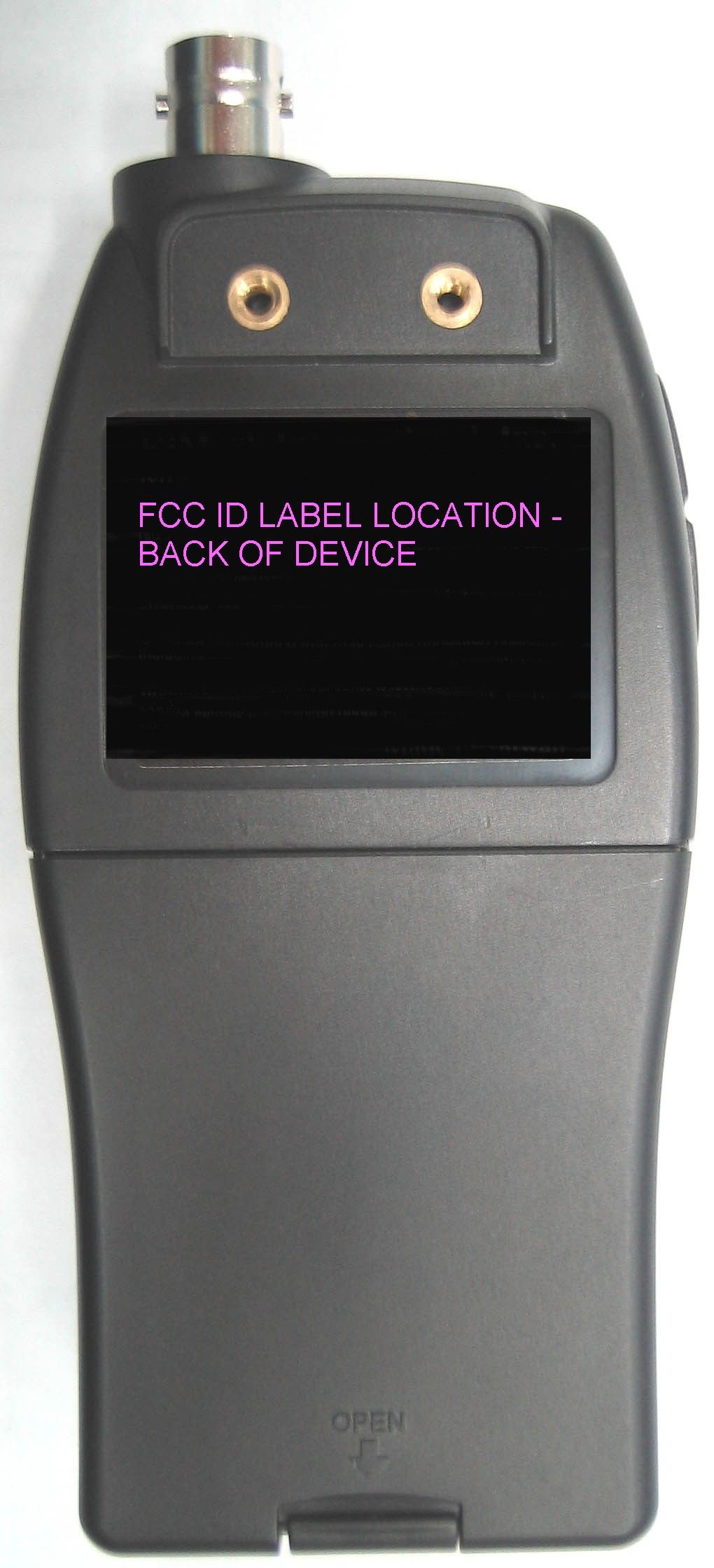
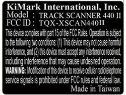
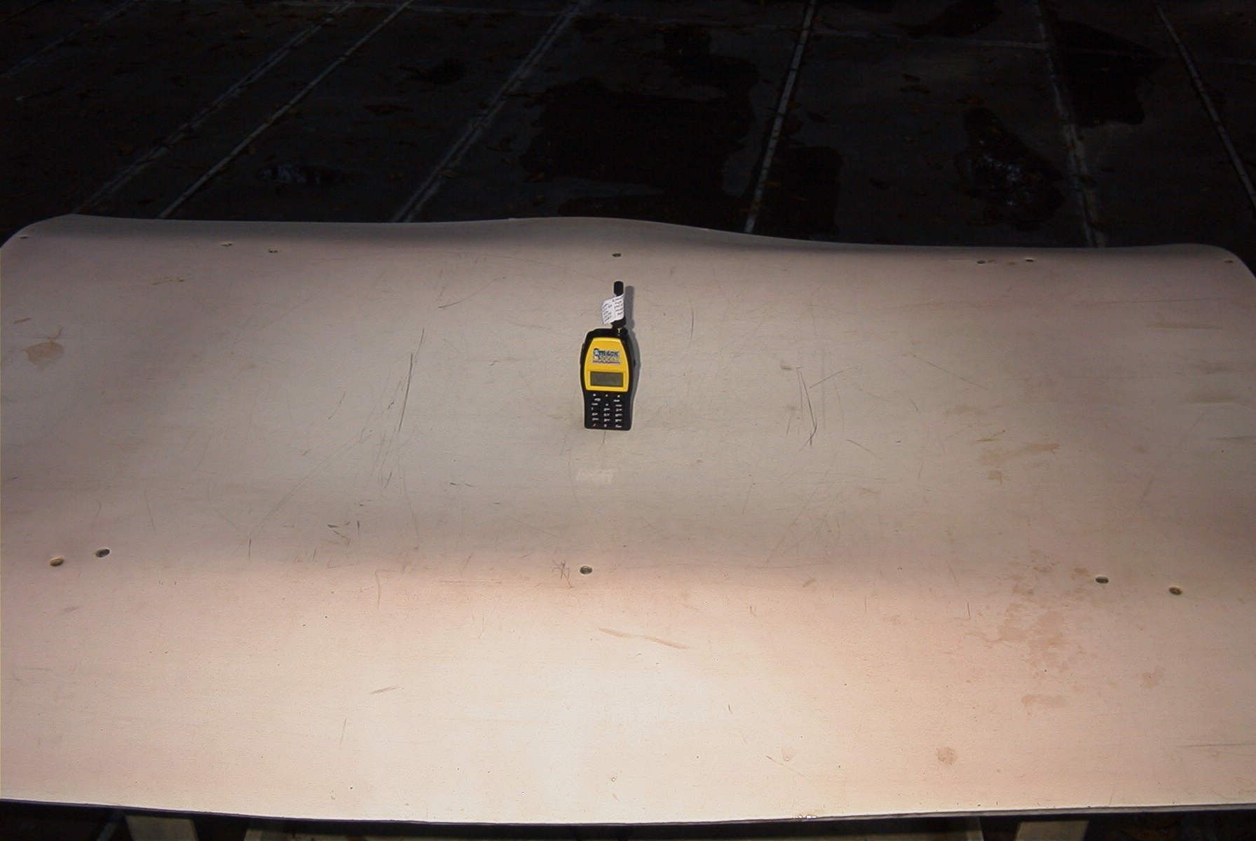
KiMARK INTERNATIONAL INC. FCC ID: TQX-XSCAN440II EXTERNAL PHOTOS
Test Report
FCC PART 15 SCANNING RECEIVER Applicant KiMARK INTERNATIONAL INC. Address 1326 CRESTVIEW DRIVE SHELBY, NC 28150 FCC ID: TQX-XSCAN440II Model Number TRACK SCANNER 440 II Product Description SCANNING RECEIVER Date Sample Received DECEMBER 18, 2006 Date Tested JANUARY 9, 2007 Tested By JOSEPH SCOGLO Approved By MARIO DE ARANZETA Report Number 3411UT6TestReport.doc Total Pages 9 Test Results PASS FAIL THE ATTACHED REPORT SHALL NOT BE REPRODUCED EXCEPT IN FULL WITHOUT THE WRITTEN APPROVAL OF TIMCO ENGINEERING, INC. 849 NW State Road 45 Newberry, Fl 32669 USA Phone: 888.472.2424 or 352.472.5500 Fax: 352.472.2030 Email: [email protected] Website: www.timcoengr.com Certificate # 0955-01 APPLICANT: KiMARK INTERNATIONAL INC. FCC ID: TQX-SSCAN440II REPORT #: V:\K\KIMARK\3411UT6\Extra3411UT6\3411UT6TestReport.doc Page 2 of 9 TABLE OF CONTENTS STATEMENT OF COMPLIANCE.................................................................................. 3 GENERAL INFORMATION .......................................................................................... 4 TEST EQUIPMENT LIST............................................................................................. 5 TEST PROCEDURE ................................................................................................... 6 RADIATED SPURIOUS EMISSIONS............................................................................ 7 POWER LINE CONDUCTED INTERFERENCE............................................................. 8 38 Db REJECTION RADIO ......................................................................................... 9 APPLICANT: KiMARK INTERNATIONAL INC. FCC ID: TQX-SSCAN440II REPORT #: V:\K\KIMARK\3411UT6\Extra3411UT6\3411UT6TestReport.doc Page 3 of 9 STATEMENT OF COMPLIANCE This equipment has been tested in accordance with the standards identified in the referenced test report. To the best of my knowledge and belief, these tests were performed using the measurement procedures described in this report and demonstrate that the equipment complies with the appropriate standards. I attest that the necessary measurements were made by me or under my supervision, at TIMCO ENGINEERING, INC. located at 849 N.W. State Road 45, Newberry, Florida 32669 USA. Certificate #0955-01 Authorized by: Mario de Aranzeta Authorized Signature: < Mario de Aranzeta> Function: Engineer Date: 1/2/2007 APPLICANT: KiMARK INTERNATIONAL INC. FCC ID: TQX-SSCAN440II REPORT #: V:\K\KIMARK\3411UT6\Extra3411UT6\3411UT6TestReport.doc Page 4 of 9 GENERAL INFORMATION The test results relate only to the items tested. DUT Description SCANNING RECEIVER Model Number TRACK SCANNER 44O II 110–120Vac/50– 60Hz DC Power DUT Power Source Battery Operated Exclusively Prototype Pre-Production Test Item Production Modifications to DUT None Test Standards FCC Part 15, Subpart B, ANSI C63.4-2003 APPLICANT: KiMARK INTERNATIONAL INC. FCC ID: TQX-SSCAN440II REPORT #: V:\K\KIMARK\3411UT6\Extra3411UT6\3411UT6TestReport.doc Page 5 of 9 TEST EQUIPMENT LIST Device Manufacturer Model Serial Number Cal/Char Date Due Date 3/10-Meter OATS TEI N/A N/A Listed 3/27/04 3/26/07 3-Meter OATS TEI N/A N/A Listed 1/11/06 1/10/09 Antenna: Biconnical Eaton 94455-1 1057 CAL 12/12/05 12/12/07 Antenna: Biconnical Eaton 94455-1 1096 CAL 10/11/06 10/11/08 Antenna: Biconnical Electro- Metrics BIA-25 1171 CAL 4/29/05 4/29/07 Analyzer Blue Tower Quasi-Peak Adapter HP 85650A 2811A01279 CAL 4/13/05 4/13/07 Analyzer Blue Tower RF Preselector HP 85685A 2926A00983 CAL 9/5/05 9/5/07 Analyzer Blue Tower Spectrum Analyzer HP 8568B 2928A04729 2848A18049 CAL 4/13/05 4/13/07 LISN Electro- Metrics ANS-25/2 2604 CAL 10/5/06 10/5/08 LISN Electro- Metrics EM-7820 2682 CAL 4/28/05 4/28/07 Antenna: Log- Periodic Eaton 96005 1243 CAL 12/14/05 12/14/07 APPLICANT: KiMARK INTERNATIONAL INC. FCC ID: TQX-SSCAN440II REPORT #: V:\K\KIMARK\3411UT6\Extra3411UT6\3411UT6TestReport.doc Page 6 of 9 TEST PROCEDURE General: This report shall NOT be reproduced except in full without the written approval of TIMCO ENGINEERING, INC. Radiation Interference: The test procedure used was ANSI Standard C63.4-2003 using a spectrum analyzer with a pre-selector. The bandwidth of the spectrum analyzer was 100 kHz with an appropriate sweep speed. The analyzer was calibrated in dB above a microvolt at the output of the antenna. The video bandwidth was always greater than or equal to the RBW. Formula Of Conversion Factors: The Field Strength at 3m was established by adding the meter reading of the spectrum analyzer (which is set to read in units of dBuV) to the antenna correction factor supplied by the antenna manufacturer. The antenna correction factors are stated in terms of dB. The gain of the Preselector was accounted for in the Spectrum Analyzer Meter Reading. Example: Freq (MHz) Meter Reading + ACF +CL = FS 33 20 dBuV + 10.36 dB/m +0.40 dB =30.36 dBuV/m @ 3m ANSI C63.4-2003 Section 10.1.7 Measurement Procedures: The unit under test was placed on a table 80 cm high and with dimensions of 1mby 1.5m. The table used for radiated measurements is capable of continuous rotation. When an emission was found, the table was rotated to produce the maximum signal strength. At this point, the antenna was raised and lowered from 1m to 4m. The antenna was placed in both the horizontal and verticals planes. APPLICANT: KiMARK INTERNATIONAL INC. FCC ID: TQX-SSCAN440II REPORT #: V:\K\KIMARK\3411UT6\Extra3411UT6\3411UT6TestReport.doc Page 7 of 9 RADIATED SPURIOUS EMISSIONS Rules Part No.: 15.109 Requirements: Frequency Limits 30 – 88 40.0 dBμV/m measured @ 3 meters 80 – 216 43.5 dBμV/m measured @ 3 meters 216 – 960 46.0 dBμV/m measured @ 3 meters Above 960 54.0 dBμV/m measured @ 3 meters Test Procedure: The procedure used was ANSI C63.4-2003. The frequency was scanned from 30 MHz to 1.0 GHz. When an emission was found, the table was rotated to produce the maximum signal strength. The DUT was measured in three (3) orthogonal planes. Test Data: Tuned Frequency MHz Em…
Text truncated - open the document above for the full version.
Contact Information
Applicant
Mark Brennan(President)
Test Firm
Timco Engineering, Inc.Sid Sanders
Technical Specifications
| # | Rule Parts | Frequency Range | Power Output |
|---|---|---|---|
| 1 | 15B | 450 MHz - 470 MHz | - |
Other Applications from KiMark International, Inc.

TQX-XSCAN440
Nov 27, 2005SCANNING RECEIVER
Equipment Class
CSR - Scanning Receiver