TR4-A4XG1-2170Cognitive Radio
ADAPT4 LLC.
Click to zoom
Application Details
- Equipment Class
- TNB - Licensed Non-Broadcast Station Transmitter
- Date of Grant
- Dec 29, 2005
- Application Purpose
- Original Equipment
- Date of Application
- Dec 29, 2005
- Equipment Note
- Cognitive Radio
- Frequency Range
- 217.00000000 - 220.00000000
- Company
- ADAPT4 LLC.
- Country
- United States
Documents & Files
Document Text
Text extracted from the exhibit documents filed with the FCC. Open a document above to read the original.
Users Manual
Adapt4, Inc. Installation Manual, Rev. 0.6 1.1 Adapt4 XG1 Radio Installation Manual A4-00103-011-01, Rev. 0.7b December 2, 2005 Adapt4, Inc. 1.2 XG1 Radio Installation Manual NOTICE Adapt4, Inc. assumes no responsibility for any errors that may appear in this document, nor does it make any commitment to update the information contained herein. However, questions regarding the information contained in this document are welcomed. Adapt4, Inc. also reserves the right to make changes to the specifications of the XG1 Series and to the information contained in this document at any time without notice. This manual is not all inclusive of our products and services. The software and procedures discussed herein are continuously evolving just as are the requirements of our customers. Its format is informal, and hopefully will stimulate as many questions as it answers. Copies of cut sheets, engineering data, customer lists, installation guides, and test procedures are all available for further information. © Adapt4, Inc. 605 N. John Rodes Blvd., Melbourne, FL 32934 Phone 321-259-5009 | Fax 321-259-4006 www.adapt4.com Adapt4, Inc. Table of Contents Adapt4 XG1 Radio .........................................................................................................1 Installation Manual ........................................................................................................1 A4-00103-011-01, Rev. 0.7 November 22, 2005............................................................1 Table of Contents ..........................................................................................................3 1.0 Overview........................................................................................................................ 4 1.1 Admin Tab ..................................................................................................................... 8 1.2 Download Tab.............................................................................................................. 10 1.3 Startup Config Tab....................................................................................................... 12 1.3.1 Network Configuration Panel .................................................................................. 13 1.3.2 Network Status Panel............................................................................................... 13 1.3.3 Antenna Pointing Tool Panel................................................................................... 13 1.4 Interfaces Config Tab................................................................................................... 16 1.5 Channels Tab ............................................................................................................... 18 1.5.1 Most Common Steps To Use ................................................................................... 19 1.5.2 Advanced features: .................................................................................................. 20 1.6 Spectrum Analyzer Tab ............................................................................................... 21 1.7 Summary ...................................................................................................................... 23 Glossary.......................................................................................................................24 Operational and Safety Warnings ..............................................................................25 Questions or Comments on This Manual ..................................................................26 Adapt4, Inc. 1.4 XG1 Radio Installation Manual 1.0 Overview The XG1 Installation Software provides a tool that enables a field installer to configure an Adapt4 XG1 radio as part of its installation in the field. The field installer “installs” the radio to make it capable of communicating on the correct network. Subsequently, the Network Operator will “commission” the site, possibly after the field installer has left the site. The commissioning process includes further configuring of the site over-the-air and coordinating the start of service with the end-user. When the site is commissioned, it may begin carrying end-user traffic. The Installation Software normally runs on a laptop computer and has the following capabilities: ∑ Network configuration – Set the XG1 radio configuration so that it can join the correct network. The network's Element Management System (EMS) will further configure the radio after it has joined the network. ∑ Software updates – Download new software distributions from the laptop to the radio. ∑ Antenna Pointing – Point the station's antenna using the laptop software's visual and audible indications of the signal strength received from the Base Station. ∑ Interface configuration – If applicable, configure the RS-232 serial ports. ∑ Channel Selection/Interference Blocking – Optionally, select blocks of channels to use and block out (“notch out”) frequency channels known to have interfering radio signals. The above list of capabilities is also a brief outline of the tasks of installing the radio. More details will be given below. Table 1.0-1 provides an equipment list needed to support use of the XG1 Installation Software. Table 1.0-1: Items Needed to Connect Radio to Computer 1. Laptop with: ∑ Windows 98 or later ∑ Ethernet port ∑ 128 MB RAM ∑ Correct time/date set 2. Ethernet cable ∑ Cross-over (if directly connected) ∑ Straight-through (if connected via hub) 3. RS-232 cable (for testing user ports) ∑ DB-9F, null cable or null adapter ∑ XG1 Installation software Adapt4, Inc. Figure 1.0-1 illustrates an XG1 radio network, which is comprised of three XG1 radio Remote Sites and a Base Station (Hub). The Remote Sites are further comprised of an antenna, the XG1 radio and end-user equipment. The end-user equipment is attached to the radio via Ethernet and/or RS-232 serial cables. The Base Station co…
Text truncated - open the document above for the full version.
Cover Letter(s)
Adapt4 Inc. 605 N. John Rodes Blvd Melbourne, FL 32934 Federal Communications Commission Authorization and Evaluation Division Confidentiality Request regarding application for certification of FCC ID: TR4-A4XG1- 2170 Pursuant to Sections 0.457 and 0.459 of the Commission’s rules, we hereby request confidential treatment of information accompanying this application as outlined below: ALL BOM’s ALL SCHEMATICS ALL BLOCK DIAGRAMS ALL THEORY OF OPERATIONS TUNING PROCEDURE The above materials contain trade secrets and proprietary information not customarily released to the public. The public disclosure of these materials may be harmful to the applicant and provide unjustified benefits to its competitors. The applicant understands that pursuant to Section 0.457 of the Rules, disclosure of this application and all accompanying documentation will not be made before the date of the Grant for this application. Sincerely, Ed Gerhardt President Adapt4
Cover Letter(s)
To: ANDREW LEIMER [email protected] FCC Equipment Authorization Branch From: Edward Gerhardt [email protected] Adapt4 CC: TCB - TIMCO Engineering Re: FCC ID: TR4-A4XG1-2170 Applicant: ADAPT4 LLC. Correspondence Reference Number: 26659 731 Confirmation Number: TC724842 Date of Original Email from Andrew Leimer: 02/17/2006 Date of Original Response from Adapt4: 03/02/2006 Subject: Adapt4 responses to Mr. Leimer’s questions regarding FCC Equipment Authorization Ref: FCC Equipment Authorization System Question 1: The electronic filing on-line User's Manual states that the Description field is for a "description of the product being marketed. Report and Order (FCC 05-57) clearly stated that cognitive radio is a type of technology. The operational description and the information in your user manual is inconsistent with the definition of FCC 05-57. Similarly, the information in your user manual is inconsistent with the information published on your web site. Please provide more appropriate description in the Description field and FCC ID Label to reflect a description of the product, not the technology used. Submit a new FCC ID label. Adapt4 response to Question 1. • The XG1 is a radio (FCC 05-057, II (14), page 6) “whose hardware limits its transmission range to permissible frequency ranges, with software selecting a particular transmission frequency within those ranges” (i.e. non-SDR). The term “cognitive” best describes Adapt4’s non-SDR technology. (IEEE P1900.1 Standard Definitions and Concepts for Spectrum Management and Advanced Radio Technologies – not all cognitive radios are software defined radios). • “Cognitive Radio” is an appropriate product description for the XG1 radio as marketed. a) Appropriate “description of product being marketed”: Cognitive Radio b) Current FCC ID Label reflects this product description. c) The marketing term “Cognitive Software-Defined Radio” (SDR) on website has been changed to “Cognitive Software Radio”. Please refer to ATTACHMENTS A and D for additional clarification. 1 Question 2: According to the Users manual, the software versions can be changed. Please explain why this device is not filed as software defined radio per FCC 05-57 requirements for such devices. Specifically, will the radio hardware be marketed with any other versions of software that will allow it to operate outside its authorized range? If yes, will any third parties (end users, professional installers, trained technicians, etc) be able to modify, configure or load different versions of software that may change the authorized radio frequency parameters. Adapt4 response to Question 2: The XG1 will not be marketed with any version of software that allows it to operate outside of the authorized range or frequency parameters. Frequency band, modulation, maximum output power, and the circumstances under which the transmitter operates in accordance with Commission rules are factory set and cannot be altered by user or third party. In accordance with FCC05-057, filing as a software defined radio is not required. Please refer to ATTACHMENT B for clarification as to user permitted changes. 2 Question 3: Provide a description of how the license holders in the authorize band under Section 90.259 can benefit from using the channel blocking-out and the spectrum analyzer features of this device and ensure that they operate only on the channels available to them Adapt4 response to Question 3: a) The license holders in the authorized band under Section 90.259 can benefit from using the channel blocking-out feature to (1) avoid interfering with primary users and (2) partition bandwidth to permit multiple XG1 networks to operate in the same geographical area. Other manufactured radios currently authorized by the FCC to operate under 90.259 (Telemetry, Secondary Use) cannot automatically avoid inferring with a primary licensed user when the primary user transmits on their authorized channel. Other 90.259 radios must be manually retuned (requires site visit and a new license frequency) prior to retransmission or permanently disabled (turned-off). b) The license holders in the authorized band under Section 90.259 can benefit from using the spectrum analyzer feature as an additional static analytical tool. The display provides only a visual snapshot of spectrum as viewed by the radio. Please refer to ATTACHMENT C for additional description of feature benefits. 3 ATTACHMENT A BACKGROUND INFORMATION RESPONSE TO QUESTION 1 Reference from FCC website: 8/02/05 Approvals for cognitive, or “smart,” radio systems that became effective August 2, 2005 will facilitate continued growth in the deployment of radio equipment employing cognitive radio technologies. These “smart” radio systems are able to operate in multiple radio modes as needed to facilitate communications between different radio services and/or to avoid interference. Manufacturers should note that the new rules require some radio systems to be filed as a Software Defined Radio (SDR) if the software can be modified by third parties. Predominate nature of most certified SDR’s (Vanu, Cisco, and Meteor) is to allow a user or third party to change frequency bands. Adapt4’s XG1 Cognitive Radio cannot be modified by user or third parties. Like most digital radios manufactured today, the XG1 incorporates digital signal processing, but does not allow a user or third party to change parameters that would degrade spurious and out-of-band emissions. As discussed with the OET several times last year, Adapt4 planned to file for equipment authorization in phases that reflect advancements in radio technologies. Phase I, December 2005 - XG1, a non-SDR cognitive radio (CR). (30Dec05) Adapt4 elected to file for a non-software defined radio certification for the XG1 because it is a specific product “whose hardware limits its transmission range to permissible frequency ranges, with software selecting a particular transmission frequency within those ranges” (i.e. non-SDR), an…
Text truncated - open the document above for the full version.
External Photos
ADAPT4 FCC ID: TR4-A4XG1-2170 EXTERNAL PHOTOS
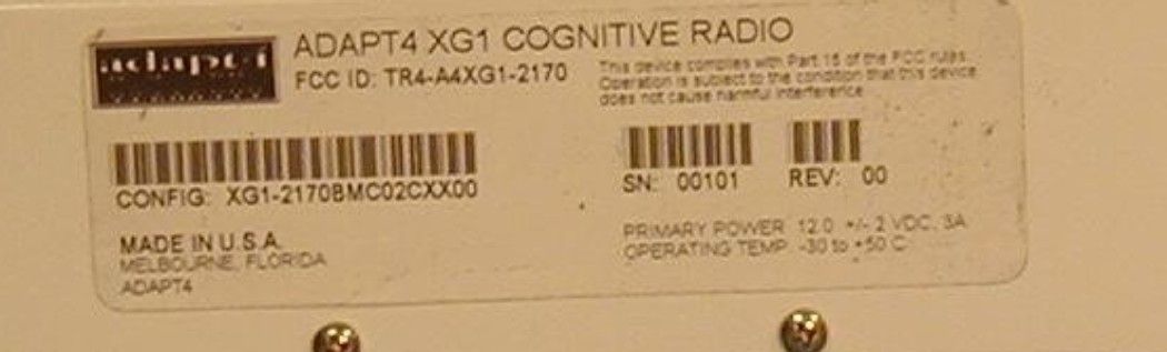
ID Label/Location Info
ADAPT4 FCC ID: TR4-A4XG1-2170 FCC ID LABEL LOCATION
Internal Photos
ADAPT4 FCC ID: TR4-A4XG1-2170 INTERNAL PHOTOS
Test Report
TIMCO ENGINEERING INC. 849 NW State Road 45 Newberry, Florida 32669 http://www.timcoengr.com 888.472.2424 F 352.472.2030 email: [email protected] APPLICANT: ADAPT4 LLC. FCC ID: Test Report Product Name: CONGITIVE RADIO FCC ID: TR4-A4XG1-2170 Applicant: ADAPT4 LLC. 605 N. JOHN RODES BLVD. MELBOURNE FL 32934 USA TR4-A4XG1-2170 REPORT #: U:\A\Adapt4\2441ZUT5\2441ZUT5TestReport.doc COVER PAGE TIMCO ENGINEERING INC. 849 NW State Road 45 Newberry, Florida 32669 http://www.timcoengr.com 888.472.2424 F 352.472.2030 email: [email protected] APPLICANT: ADAPT4 LLC. FCC ID: APPLICANT: ADAPT4 LLC FCC ID: TR4-A4XG1-2170 TABLE OF CONTENTS LIST TEST REPORT: PAGE 1...........GENERAL INFORMATION & TECHNICAL DESCRIPTION PAGE 2...........TECHNICAL DESCRIPTION CONTINUED RF POWER OUTPUT AUDIO FREQUENCY RESPONSE AUDIO LOW PASS FILTER PAGE 3-5.........OCCUPIED BANDWIDTH PAGE 6...........SPURIOUS EMISSIONS AT ANTENNA TERMINALS PAGE 7...........METHOD OF MEASURING SPURIOUS EMISSIONS AT ANTENNA TERMINALS PAGE 8...........RADIATED SPURIOUS EMISSIONS PAGE 9...........METHOD OF MEASURING RADIATED SPURIOUS EMISSIONS PAGE 10..........FREQUENCY STABILITY PAGE 11..........EQUIPMENT LIST PAGE 12..........MPE CALUCATION EXHIBITS CONTAINING: REQUEST FOR CONFIDENTIALITY BLOCK DIAGRAM SCHEMATIC PARTS LIST USERS MANUAL LABEL SAMPLE LABEL LOCATION EXTERNAL PHOTOGRAPHS INTERNAL PHOTOGRAPHS TUNING PROCEDURE OPERATIONAL DESCRIPTION TEST SET UP PHOTOGRAPH TR4-A4XG1-2170 REPORT #: U:\A\Adapt4\2441ZUT5\2441ZUT5TestReport.doc TABLE OF CONTENTS TIMCO ENGINEERING INC. 849 NW State Road 45 Newberry, Florida 32669 http://www.timcoengr.com 888.472.2424 F 352.472.2030 email: [email protected] APPLICANT: ADAPT4 LLC. FCC ID: GENERAL INFORMATION REQUIRED FOR CERTIFICATION OF A LICENSED TRANSMITTER 2.1033(c)(1)(2) ADAPT4 LLC. will manufacture the FCCID: TR4-A4XG1-2170 CONGITIVE RADIO in quantity, for use under FCC RULES PART 90. ADAPT4 LLC. 605 N. JOHN RODES BLVD. MELBOURNE FL 32934 2.1033(c) TECHNICAL DESCRIPTION 2.1033(c)(3) Instruction book. A draft copy of the instruction manual is included. 2.1033(c)(4) Type of Emission: 6K0F1D 90.209 90.207 Bn = 2M + 2DK M = 4800 D = 600 Bn = 2(4800/2)+2(600) = 6.0k 2.1033(c)(5) Frequency Range: 217-220 MHz 90.209 (b)(5) 2.1033(c)(6)(7) Power Output shall not exceed 59 Watts into a 50 ohm 90.205 resistive load. There are no user power controls. 2.1033(c)(8) DC Voltages and Current into Final Amplifier: POWER INPUT: FINAL AMPLIFIER ONLY INPUT POWER: (12.0 V)(0.5A) = 6.00 Watts 2.1033(c)(9) Tune-up procedure. The tune-up procedure is included. 2.1033(c)(10) Complete Circuit Diagrams: The circuit diagram is included. The block diagram is included. 2.1033(c)(11) Description of all circuitry and devices provided for determining and stabilizing frequency is included in the circuit description. 2.1033(c)(12) A photograph or drawing of the equipment identification label is included. TR4-A4XG1-2170 REPORT #: U:\A\Adapt4\2441ZUT5\2441ZUT5TestReport.doc Page 1 of 12 TIMCO ENGINEERING INC. 849 NW State Road 45 Newberry, Florida 32669 http://www.timcoengr.com 888.472.2424 F 352.472.2030 email: [email protected] APPLICANT: ADAPT4 LLC. FCC ID: 2.1033(c)(13) Photographs of the equipment of sufficient clarity to reveal equipment construction and layout and label location are included. 2.1033(c)(14) For equipment employing digital modulation, a detailed description of the modulation technique. This UUT uses FSK to modulate the transmitter. 2.1033(c)(15) The data required for 2.1046 through 2.1057 is submitted below. 2.1046(a) RF POWER OUTPUT RF power is measured by connecting a 50-ohm, resistive wattmeter to the RF output connector. With a nominal battery voltage, and the transmitter properly adjusted the RF output measures: OUTPUT POWER: 0.812 Watts Conducted Audio Oscillator Power Meter Transmitter under Test 2.1047(a) Voice modulation characteristics: This UUT does not have an audio frequency responses plot. 2.1049 Audio Low Pass Filter This UUT does not have a low pass filter. TR4-A4XG1-2170 REPORT #: U:\A\Adapt4\2441ZUT5\2441ZUT5TestReport.doc Page 2 of 12 TIMCO ENGINEERING INC. 849 NW State Road 45 Newberry, Florida 32669 http://www.timcoengr.com 888.472.2424 F 352.472.2030 email: [email protected] APPLICANT: ADAPT4 LLC. FCC ID: 2.1049 Occupied bandwidth: 2.1049(c) EMISSION BANDWIDTH: 90.210 (b) 25kHz Channel Spacing: Data in the plots show that on any frequency removed from the assigned frequency by more than 50%, but not more than 100%: At least 25dB. On any frequency removed from the assigned frequency by more than 100%, but not more than 250%: At least 35 dB. On any frequency removed from the assigned frequency by more than 250%, of the authorized bandwidth: At least 43 + 10log(P)dB. 90.210 (c) 12.5kHz Channel Spacing Not Equipped with a Low Pass Filter: For transmitters that are not equipped with an audio low pass filter pursuant to S90.211 (b), the power of any emission must be attenuated below the un-modulated carrier output power as follows; (1) On any frequency removed from the center of the authorized bandwidth by a displacement frequency (fd in kHz) of more than 5 kHz but not more than10 kHz: At least 83 log (fd/5) dB; (2) ON any frequency removed from the center of the authorized bandwidth by a displacement frequency (fd in kHz) of more than 10 kHz, but not more than 250% of the authorized bandwidth: At least 29 log(fd2/11)dB or 50 dB, whichever is the lesser attenuation; (3) On any frequency removed from the center of the authorized bandwidth by more than 250% of the authorized bandwidth: At least 43 + 10 log(Po)dB. 90.210 (d ) Emission Mask D - 12.5 kHz channel BW equipment: For transmitters designed to operate with a 12.5 kHz channel bandwidth, any emission must be attenuated below the power (P) of the highest emission contained within the authorized bandwidth as follows: (1) On any frequency from the center of the authorized bandwidth f0 to 5.625 kHz removed from f0: Zero dB. (2) On any frequency from…
Text truncated - open the document above for the full version.
Contact Information
Applicant
PAUL GREENIS(VICE PRESIDENT, MARKETING & SALES)
Test Firm
Timco Engineering, Inc.S Sanders
Technical Specifications
| # | Rule Parts | Frequency Range | Power Output | Emission | Tolerance |
|---|---|---|---|---|---|
| 1 | 90 | 217 MHz - 220 MHz | 812.00 mW | 6K25GXD | 1.0000000000 ppm |