TRGSJ401ABluetooth Handsfree Carkit
Sungjin Techwin Co., Ltd.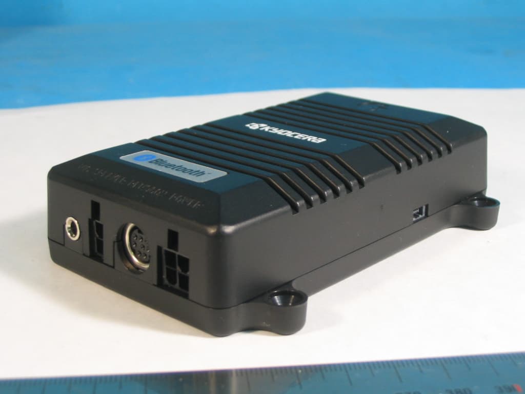
Click to zoom
Application Details
- Equipment Class
- DSS - Part 15 Spread Spectrum Transmitter
- Date of Grant
- Nov 10, 2005
- Application Purpose
- Original Equipment
- Date of Application
- Nov 10, 2005
- Equipment Note
- Bluetooth Handsfree Carkit
- Frequency Range
- 2402.00000000 - 2480.00000000
- Company
- Sungjin Techwin Co., Ltd.
- Country
- South Korea
Documents & Files
Document Text
Text extracted from the exhibit documents filed with the FCC. Open a document above to read the original.
Users Manual
(Figure 3) Power cable (Figure 2) Talk Button Volume(-) Green LED Red LED (Figure 1) 4 Feature Noise Cancellation System Superior Sound Quality Full Duplex System Simple Operation Easy Set Up Main Control Box Power Cable Speaker Microphone Remote Controller Connection Diagram Volume(+) 5 User Guide Remote controller function (Figure 2) BUTTONSTalk button Used for accept, end, reject, redial functions Volume (+) button For increasing the speaker volume Volume (-) button For decreasing the speaker volume LEDRed light For indication of the Handsfree device operation Green light For indication of Bluetoothlink status Green flashing light during paring Installation guide 1. Insert the microphone jackinto the control box per Figure 1. 2. Place the microphonein the visor as in Figure 4. Hide the microphone cable through A Pillar. Note: Make sure microphone and cable do not interfere with safety of the vehicle operation. It is highly recommended to place front of the microphone directly facing the operator for the best result. 3. Connect the Speaker cable jackinto the main control box. Place the speaker in the desirable place in the front passenger compartment. Strongly recommend placing the speaker under the passenger side dashboard. Note : Professional installer should permanently mount the speaker to the safe area with the screws. 4. Connect the Remote controllerjackinto the main control box. Secure the Remote controller near by the driver side or center console with the Velcro pads where user can easily reach the remote controller without compromising safety while operating the vehicle. 6 5. Place the Main control boxunder the desh. Note : Professional installer should secure the Main control box to under desh by installing wire tie. 6. Connect the Power cableinto the car power source and connect the radio mute cable. Professional installation of the power & mute cables 1) Disconnect the power cable from the car battery. 2) Connect the ground wire to the car ground. 3) Connect the power wire to the ignition. 4) Connect the audio mute-1 wire to the audio head unit. 5) Connect the power cable from the car battery. 6) Turn the ignition ON and confirm that the power of the SJ401A is on (Green LED-on). 7) Turn on the audio and check if you can hear the radio. a) If so, you are successfully installed the SJ401 unit into the car. b) If there is no sound, disconnect the power cable from the car battery and then change the audio mute-1 wire to the audio mute-2 wire and the audio mute-2 wire connect the audio head unit. Note : The car audio manufacturers use either the high or low audio mute level. Therefore, it is necessary to check the audio mute level. The audio will automatically mute upon receipt or during the phone conversation and then return to the previous volume level after completion of the phone conversation. If you have the cigar cable you can alternate use the power cable or the cigar cable for power connection. Pairing your mobile phone with the SJ401A Follow the pairing instruction for the first use, after that the unit will pair automatically. Pairing as the Handsfree mode When power is on (confirmed by blue LED light), press the VOL+ button for 5 seconds on the Remote controller. You will hear a beep tone. The Handsfree device is ready to be paired with the mobile phone. The SJ401A Bluetoothdevice pin code is : 1234 7 Mobile phone manual pairing 1. Browse the mobile phone menu and find connectivity and/or Bluetoothconnection section. 2. Select the search for a new Handsfree device and allow the mobile phone to find the SJ401A. Note: Each mobile phone has a different phone menu so you may need to refer to your manufacturers instruction to find how to connect a new Bluetoothdevice. 3. The Bluetoothcode for theSJ401 should appear on your mobile phone screen. 4. Press the connect button with the Handsfree option on your mobile phone. Note: Please return to the pairing instructions if the Bluetoothcode does not appear on the mobile phone screen. The green LED light should flash during pairing. 5. The mobile phone should prompt for the pin code, insert the SJ401A pin code 1234 by using the mobile phone pin code. 6. The mobile phone should confirm that it is establishing new connection. 7. Close the menu. The pairing is now completed. Note: The green LED light illuminated after successful pairing. Please adjust the volume to your preference by using the volume keys. Using the SJ401A as the Handsfree device When the Handsfree is ringing, To accept callPress TALK button To reject callDouble click TALK button To end call Press TALK button To control VolumePress VOL+/VOL- 8 Call transfer, The Call transfer function is for switching the call from handsfree to the mobile phone for the private conversation without disconnecting the call. Switching from Handsfree to mobile phone : Press and hold TALK button(3 seconds) Switching back to Handsfree : Press and hold TALK button(3 seconds) When the Handsfree is idle, Voice dial :Press and hold TALK button(3 seconds )/ Announce name after a beep. Note: This function works if phone has the voice dialing capability Last number redial :Double click on TALK button Note: This function works if phone has the last number dialing feature. Using the SJ401A as the Headset device Pairing as the Headset mode 1. When the power is on, press the VOL+ button for 5 seconds. 2. The beep tone should be heard. 3. After hearing the beep tone, repeat the procedure by pressing the VOL+ button for another 5 seconds. 4. The second beep tone should be heard indicating the SJ401A Handsfree unit is ready to be paired with your mobile phone. Functions are as same as the Handsfree mode Note: Your phone must contain the special features such as voice dialing, last number dial, etc to be used in the SJ401A. It is possible the SJ401A buttons might not operated according to the Handsfree operation manual if your Bluetoothphone has an unusual Bluetoothprogram. 9 The user can change positi…
Text truncated - open the document above for the full version.
Cover Letter(s)
Sungjin Techwin Co., Ltd Chief, Equipment Approval Services Federal Communications Commission PO Box 358315 Pittsburg, PA 15251-5315 Daejeon , October 31,2005 Authorization Letter Dear Sir or Madam: We, Sungjin Techwin Co., Ltd. hereby authorize TÜV Rheinland Korea Ltd. 2F., Sehwa Bldg. 157-16 Samsung-dong, Gwangnam-Gu, Seoul 135-090, R.O.K. To act as our agent and to process and sign on our behalf for equipment authorization under FCC Part 15, Subpart C. This authorization is applicable for the product: SJ401A with FCC ID: TRGSJ401A. Sincerely, Signature Printed Name : Kyea Kwang Lee Title : CEO
Cover Letter(s)
Sungjin Techwin Co., Ltd Federal Communications Commission Authorization and Evaluation Division 7435 Oakland Mills Road Columbia, MD 21046 Daejeon , October 31,2005 REQUEST FOR CONFIDENTIALITY, FCC ID: TRGSJ401A Pursuant to Sections 0.457(d)(1)(ii) and 0.459 of the Commission's Rules, the Applicant hereby requests confidential treatment of information accompanying as outlined below: • Schematic drawing • Bill of Materials • Block Diagram The above materials contain trade secrets and proprietary information not customarily released to the public. Public disclosure of these matters might be harmful to the Applicant and provide unjustified benefits to its competitors. The Applicant understands that pursuant to Rule 0.457(d)(1)(ii), disclosure of this Application and accompanying documentation will not be made before the date of the Grant for this application. Sincerely, Signature : Printed Name: Kyea Kwang Lee Title : CEO
External Photos
TÜV Rheinland Product Safety GmbH External Photos 13005186 Revision No : 1.0 Page: 1 of 2 * External view 1. Front side 2. Right side view TÜV Rheinland Product Safety GmbH External Photos 13005186 Revision No : 1.0 Page: 2 of 2 3. Rear side 4. Left side view
ID Label/Location Info
TÜV Rheinland Product Safety GmbH FCC Label and Location Revision No : 1.0 Page: 2 of 2 * FCC Label and Location * Label 45mm Label Position 60mm
Internal Photos
TÜV Rheinland Product Safety GmbH Internal Photos 13005186 Revision No : 1.0 Page: 1 of 3 * Internal view 1. Internal TÜV Rheinland Product Safety GmbH Internal Photos 13005186 Revision No : 1.0 Page: 2 of 3 2. PCP Top View with Bluetooth module shield case 3. PCP Top View without Bluetooth module shield case Bluetooth Module Bluetooth Antenna Bluetooth Module Bluetooth Antenna TÜV Rheinland Product Safety GmbH Internal Photos 13005186 Revision No : 1.0 Page: 3 of 3 4. PCP Bottom View
Operational Description
TÜV Rheinland Product Safety GmbH Am Grauen Stein D - 51105 Köln EUT operational and EUT description Seite 1 von 2 Page 1 of 2 S S J J T T e e c c h h w w i i n n i i n n t t r r o o d d u u c c e e s s S S J J 4 4 0 0 1 1 A A SJ Tech Bluetooth Install type handsfree systems are true universal Bluetooth system that is capable of connecting with all Bluetooth equipped mobile phones. The superior audio quality and the connectivity is the key benefiting feature of SJ Tech Bluetooth handsfree s ytems. Both systems feature the superior noise cancellation and echo eliminating circuits that will allow user to communicate to full extend according to the mobile phone signal reception. SJ Bluetooth handsfree systems are true full duplex systems allowing users to continuously communicate with others without pause. SJ401, Install type handsfree system can be professionally wired to mute the audio system. B B e e s s a a f f e e , , b b e e f f r r e e e e a a n n d d e e x x p p r r e e s s s s Y Y o o u u r r s s e e l l f f t t h h r r o o u u g g h h S S J J T T e e c c h h w w i i n n B B l l u u e e t t o o o o t t h h H H a a n n d d s s f f r r e e e e k k i i t t ! ! H H a a n n d d s s f f r r e e e e C C a a r r K K i i t t Specification Input power : DC10~28V, 2A(free voltage) Fuse : 250V/2A Indicator : 2 LED lights Speaker : 4ohm/5W(Free edge type) Microphone : Array Mic.-47dB±2dB Full duplex operation with noise cancellation Bluetooth specification v1.1 compliant Supported model : All wireless phones with the Bluetooth capabilities including the Sony Ericsson T610, T68series, T39, R520, P800, Nokia8910, 6310 series, Siemens S55, Motorola V600 series, etc. TÜV Rheinland Product Safety GmbH Am Grauen Stein D - 51105 Köln EUT operational and EUT description Seite 2 von 2 Page 2 of 2 General EUT Information Type Transmitter Receiver FCC Classification FHSS Sequence Spread Spectrum ( FHSS) FHSS Sequence Spread Spectrum ( FHSS) Operating frequency range 2402 – 2480 MHz 2402 – 2480 MHz Bands of operation 2.400 – 2.4835 GHz 2.400 – 2.4835 GHz Number of Channels 79 79 Channel Separation 1MHz 1MHz Type of Antenna Chip Antenna Chip Antenna Power Supply DC 12 V Vehicular Battery DC 12 V Vehicular Battery
Test Report
TÜV Rheinland Product Safety GmbH REPROT NO : 13005186 Revision No : 1.1 Page: 1 of 47 FCC Part 15 TEST REPORT November 3, 2005 TUV Rheinland Korea Ltd. TÜV Rheinland Product Safety GmbH REPROT NO : 13005186 Revision No : 1.1 Page: 2 of 47 TEST REPROT CERTIFICATION Applicant : SungJin Techwin Co., Ltd Adderss : 256-8 In-Dong, Dong- Gu, Daejeon- Shi, 300-828, Korea EUT Name : Bluetooth Handsfree Car Kit Model No. : SJ401A Serial No. : Engineering Sample FCCID : TRGSJ401A Testing location : LG Innotek Co.,Ltd. 133, Gongdan-dong, Gumi-City , Gyeongbuk 730-703, R.O.K Applied specification : FCC Part 15 Test result : The above mentioned test item passed. Tested by : Gye-Woog Lee Date Signature Reviewed by : Uon-Chae Song Date Signature I HEREBY CERTIFY THAT the data shown in this report were made in accordance with the procedures given in the applied specification and I assume full responsibility for accuracy and completeness of these data. Note : This test report relates to the a. m. test item. Without permission of the test center this test report is not permitted to be duplicated in extracts. This test report does not entitle to carry any test mark on this or similar products. November 3, 2005 November 3, 2005 TÜV Rheinland Product Safety GmbH REPROT NO : 13005186 Revision No : 1.1 Page: 3 of 47 Contents 1. GENERAL INFORMATION................................................................................................. 5 1.1 PRODUCT DESCRIPTION............................................................................................... 5 1.2 PROJECT DATA............................................................................................................ 5 1.3 APPLICANT................................................................................................................. 5 1.4 MANUFACTURER......................................................................................................... 5 2. EUT INFORMATION........................................................................................................ 6 2.1 GENERAL EUT INFORMATION....................................................................................... 6 2.2 CENTER FREQUENCY OF TESTED CHANNEL................................................................... 6 2.3 T EST ENVIRONMENT.................................................................................................... 6 2.4 ACCESSORIES AND ANCILLARY EQUIPMENT.................................................................. 6 3. TESTING FACILITIES....................................................................................................... 7 4. EUT DESCRIPTION AND OPERATIONAL DESCRIPTION....................................................... 7 5. TEST SET-UP................................................................................................................. 7 5.1 PRINCIPLE OF CONFIGURATION..................................................................................... 7 5.2 OPERATIONAL MODES................................................................................................. 7 5.3 A PPLIED SPECIFICATION.............................................................................................. 7 6. TEST REPORT SUMMARY............................................................................................... 8 7. TEST RESULTS.............................................................................................................. 9 7.1 A NTENNA CONNECTOR REQUIREMENTS........................................................................ 9 7.2 AC CONNECTED EMISSION......................................................................................... 10 7.3 CARRIER FREQUENCY SEPARATION............................................................................ 11 7.4 TIME OF OCCUPANCY(DWELL TIME) ............................................................................ 13 7.5 20 DB BANDWIDTH..................................................................................................... 15 7.6 NUMBER OF HOPPING FREQUENCIES REQUIREMENTS.................................................. 19 7.7 PSEUDORANDOM FHS AND EQUAL HOPPING FREQUENCY USE REQUIREMENTS............. 21 7.8 RECEIVER INPUT BANDWIDTH REQUIREMENTS............................................................. 22 TÜV Rheinland Product Safety GmbH REPROT NO : 13005186 Revision No : 1.1 Page: 4 of 47 7.9 PEAK OUTPUT POWER............................................................................................... 23 7.10 BAND-EDGE COMPLIANCE........................................................................................ 27 7.11 SPURIOUS CONDUCTED EMISSIONS........................................................................... 31 7.12 SPURIOUS RADIATED EMISSIONS.............................................................................. 42 8. LIST OF TEST AND MEASUREMENT INSTRUMENTS.......................................................... 45 9. COMPLEMENTARY MATERIALS...................................................................................... 47 9.1 ID LABEL AND LOCATION INFORMATION...................................................................... 47 9.2 OPERATIONAL DESCRIPTION...................................................................................... 47 9.3 TEST SETUP PHOTOS................................................................................................. 47 9.4 INTERNAL PHOTOS.................................................................................................... 47 9.5 EXTERNAL PHOTOS................................................................................................... 47 9.6 USER MANUAL.......................................................................................................... 47 9.7 TECHNICAL DOCUMENTS............................................................................................ 47 TÜV Rheinland Product Sa…
Text truncated - open the document above for the full version.
Test Setup Photos
TÜV Rheinland Product Safety GmbH Test setup photos 13005186 Revision No : 1.0 Page: 1 of 5 * Test set-up 1. Radiated Set up TÜV Rheinland Product Safety GmbH Test setup photos 13005186 Revision No : 1.0 Page: 2 of 5 2 Spurious Radiated Emissions 2.1 Radiated test ( 30 MHz ~ 1GHz ) TÜV Rheinland Product Safety GmbH Test setup photos 13005186 Revision No : 1.0 Page: 3 of 5 2.2 Radiated test ( 1 GHz ~ 13GHz ) TÜV Rheinland Product Safety GmbH Test setup photos 13005186 Revision No : 1.0 Page: 4 of 5 2.3 Radiated test ( 13 GHz ~ 18GHz ) TÜV Rheinland Product Safety GmbH Test setup photos 13005186 Revision No : 1.0 Page: 5 of 5 2.4 Radiated test ( 18 GHz ~ 25GHz )
Contact Information
Applicant
Gwan Yong Park
Technical Contact
T�V Rheinland Korea LtdUon-Chae Song
[email protected]+82-2-539-1781
2F., Sehwa Bldg. 157-16 · Seoul · South Korea
Non-Technical Contact
Gwan Yong ParkGwan Yong Park
[email protected]+82-2-2639-8711
Test Firm
LIG Nex1 Co., Ltd.Hyo-Jeung Cho
Technical Specifications
| # | Rule Parts | Frequency Range | Power Output |
|---|---|---|---|
| 1 | 15C | 2.40 GHz - 2.48 GHz | 500.00 µW |
Other Applications from Sungjin Techwin Co., Ltd.
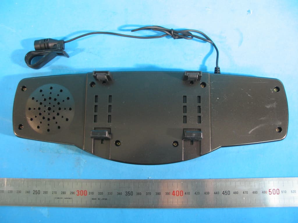
TRGMHF-R330BT
Nov 17, 2005BLUETOOTH REARVIEW MIRROR HANDS-FREE CAR KIT
Equipment Class
DSS - Part 15 Spread Spectrum Transmitter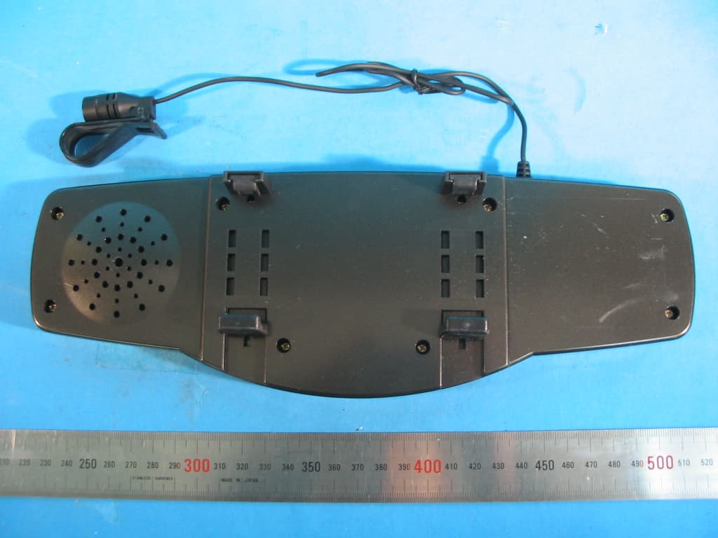
TRGMHF-R220BT
Nov 17, 2005BLUETOOTH REARVIEW MIRROR HANDS-FREE CAR KIT
Equipment Class
DSS - Part 15 Spread Spectrum Transmitter