TS23237002002Speedometer
Bell Sports (Asia) Limited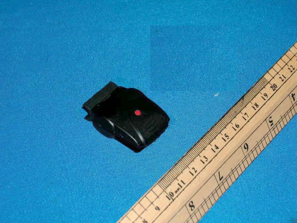
Click to zoom
Application Details
- Equipment Class
- DCD - Part 15 Low Power Transmitter Below 1705 kHz
- Date of Grant
- May 23, 2006
- Application Purpose
- Original Equipment
- Date of Application
- May 23, 2006
- Equipment Note
- Speedometer
- Frequency Range
- 0.13000000 - 0.13000000
- Company
- Bell Sports (Asia) Limited
- Country
- Hong Kong
Documents & Files
Document Text
Text extracted from the exhibit documents filed with the FCC. Open a document above to read the original.
Users Manual
FreeFitFreeFitFreeFi ™ BE FREE • BE FIT • BE WIRELESS INSTALLATION .........................................2 PROGRAMMING THE COMPUTER ..........4 QUICKSTART ..........................................6 TROUBLESHOOTING ..............................9 FCC WARNING .....................................10 INSTALACIÓN .........................................11 PROGRAMACIÓN DEL ORDENADOR ....13 ARRANQUE RÁPIDO ............................15 RESOLUCIÓN DE PROBLEMAS .............18 ADVERTENCIA DE LA SEGURIDAD .......19 INSTALLATION .......................................20 CONFIGURATION DE L’ORDINATEUR ..22 QUICKSTART ........................................24 DÉPANNAGE ........................................28 AVERTISSEMENT (FCC) ........................29 FreeFit_Manual4.indd 19/14/05 12:37:08 PM WARNING! • Improper installation of this or any other bike computer can result in an accident. Read instructions carefully. • Call 1-800-456-BELL if you have any questions about installation. • Check mounting hardware and transmitter installation before each ride for adjustment and secure fi t. • This computer will not fi t all bikes. If you cannot get a secure installation per the instruction manual, do not use this computer. ! INSTALLATION Sensor Mounting Bracket Cable Ties (2) Computer Battery (3.0V/CR2032) O-Rings (3) Computer Unit MagnetMagnet 2 FreeFit_Manual4.indd 29/14/05 12:37:10 PM 3 Sensor or Magnet 5mm Sensor MagnetMagnet Sensor Top View Bicycle fork Top View BATTERY:Install the new battery with the positive (+) pole facing outward (Figure 1). After changing the battery all settings are erased. Make sure to write down the Odometer value before changing the battery so you can later re-enter it in the odometer. Clamp the magnet to a spoke on the right side of the front wheel (Figure 2). Make sure that the magnet is facing the outside of the wheel so that the fl at side of the magnet passes in front of the sensor. Attach the speedometer sensor to the right fork of the front wheel using the two cable ties provided. Make sure the metal side of the sensor is facing the wheel. Do not fully secure the cable ties yet, as the sensor location might require further adjustments (Figure 3). Adjust the sensor and magnet location so that clearance between the two is no greater than 1/5" (5mm) (Figure 4). Magnet should pass by the tip of the sensor. Remove the adhesive tape shield on the back of the bracket and position the bracket on the handlebar of the bicycle. Fasten the O-ring around the top edge of the bracket and wrap around the underside of the handlebar and attach to the bottom edge of the bracket. Insert the computer into the mounting bracket and twist to the right to lock into place. INSTALLATION 23 1 4 FreeFit_Manual4.indd 39/14/05 12:37:11 PM 4 Wheel Size Input The fl ashing number "2124" is the preset value. To determine the correct wheel factor, refer to the table shown. Set the wheel factor by pressing the Right button until the correct setting appears. Press the Left button to lock in the correct digit. Repeat until all four digits are entered. Km or Mile Selection After setting the Wheel Factor the Km/M selection will appear. Press the Right button to choose kilometer or mile. Press the Left button to confi rm. 12 or 24 Hour Format Selection After the Km/M input selection, the clock format screen will appear. Press the Right button to choose between the two formats. Press the Left button to confi rm. PROGRAMMING THE COMPUTER Road Bike 20" 1596 22" 1759 24" 1916 26" 2073 26.6 2124 Mountain Bike 24" 1888 26" 2045 27" 2155 28" 2237 FreeFit_Manual4.indd 49/14/05 12:37:12 PM 5 KG or LB Selection After the hour format selection, the Kg/Lb selection will appear. Press the Right button to choose between Kilograms (Kg) or Pounds (Lb). Press the Left button to confi rm choice. Once the weight unit is selected, the computer will ask the user to enter his/her weight. This will allow the computer to accurately estimate the number of calories burned while riding. To enter the correct weight, press the Right button until the correct digit appears. Press the Left button to lock in the correct digit. Repeat until all digits are entered. NOTE:The weight entered should be between 80–499Lb or 35–199Kg. The speedometer is now ready to use. Clock Set the time by pressing and holding the Right button until the hour is fl ashing. To set, press the Right button until desired setting is displayed. Press the Left button to confi rm. Repeat steps for the minute setting. PROGRAMMING THE COMPUTER FreeFit_Manual4.indd 59/14/05 12:37:12 PM 6 Now that the speedometer is confi gured, insert the computer into the bracket and twist to the right to lock in place. To check for proper installation, spin the front wheel. The speed tendency icon in the upper left corner of the screen should be turning as the computer starts recording data (Refer to TROUBLESHOOTING in case of problems). QUICKSTART UPPER SCREEN • Current Speed (SPD) 0–199.9 Km/hr or M/hr • Calories Burned (CAL) 0–999.9 Calories Burned • Speed Comparison (+ or-) • Speed Tendency LOWER SCREEN • Trip Distance (DST) 0–999.9 Km or M • Trip Timer (TM) 9 hrs 59 min 59 sec • Odometer (ODO) • Average Speed (AVS) • Maximum Speed (MXS) • Clock FreeFit_Manual4.indd 69/14/05 12:37:13 PM 7 Current Speed (SPD) Current Speed represents instantaneous speed. It is displayed on the upper screen. The speedometer measures speeds up to 200Km/hr or 125 M/hr. If no keys are touched and no movement sensed from the bicycle for fi ve minutes, the speedometer will go into sleep mode. Press any key to reactivate. Calories Burned (CAL) Calories Burned is displayed on the upper screen. It represents the accumulated number of calories burned while riding. The calorie count on the screen will start over once 999 calories have been burned. Calories Burned can be reset at any time by pressing and holding the Left button when "CAL" is displayed on the screen. Speed Comparison (+ or -) "+" or "-" ap…
Text truncated - open the document above for the full version.
Block Diagram
CM3010RE Transmitter Block Diagram of Transmitter Input Circuit MCU Transmission Circuit Antenna
External Photos
Test Setup FCC ID : TS23237002002 External Photo - Front External Photo - Rear
Internal Photos
Test Setup FCC ID : TS23237002002 Internal Photo - 1 Internal Photo - 2
Operational Description
CM3010RE Transmitter Description Input Circuit: Magnet triggers the magnetic sensor to receive signal MCU: Input signal is modulated by MCU Transmission Circuit: Modulated signal is amplified and passed to the Antenna for transmission. Antenna: Modulated 130kHz signal is transmitted through the antenna.
Schematics
1234 A B C D 4321 D C B A 0 JEFLY INTERNATIONAL LIMIT 剢屢笳 software 0 TM600 0T0 29-Aug-200511:07:45 C:\My Documents\CM3010RE\Speed\E30259-00_SD2013CD_VER01.ddb - Documents\SD2013CD_ver01.Sch Title Size:Number: Date: File: Revision: Sheetof Time: A4 C15 2.2u R10 100K R847K SW2SW-PB X2 32768Hz Q2 BC817-25 6B C13 300P C16 0.056u C18 0.01u T3 97:49 BAT2 CR2032 VCC VCC VCC 25mm BAR T1-1 T1-2 T1-3 T1-4 C17 510P T2 T1-1T1-2T1-3T1-4 TP5 TP6 TP7 C14 1uF PRTD[7] 21 PRTD[6] 22 PRTD[5] 23 PRTD[4] 1 PRTD[3] 2 PRTD[2] 3 PRTD[1] 4 PRTD[0] 5 PRTC[3] 6 OPO 13 RSTP_N 14 FXO 15 FXI 16 TSTP_P 17 SXO 18 SXI 19 V D D 2 0 G N D 1 0 HE83000 PRTC[2] 7 PRTC[1] 8 PRTC[0] 9 MCU2 U1 VCC R7 51K C12 2200P VCC INPUT11 INPUT2 C1 0.1U C11 20P C9 20P C3 0.1U R6 51K VCC R1 56K C2 30P VCC SD2013CD Ver01 PDF created with pdfFactory Pro trial version www.pdffactory.com
Test Report
• The test results reported in this test report shall refer only to the sample actually tested and shall not refer or be deemed to refer to bulk from which such a sample may be said to have been obtained. • This report shall not be reproduced except in full without prior authorization from Intertek Testing Services Hong Kong Limited. • For Terms And Conditions of the services, it can be provided upon request. • The evaluation data of the report will be kept for 3 years from the date of issuance. Intertek Testing Services Hong Kong Ltd. 2/F., Garment Centre, 576 Castle Peak Road, Kowloon, Hong Kong. Tel: (852) 2173 8888 Fax: (852) 2371 0521 Website: www.hk.intertek-etlsemko.com Bell Sports (Asia) Ltd. Application For Certification (FCC ID: TS23237002002) Transmitter 0517036 DL/ Sandy Lee December 5, 2005 INTERTEK TESTING SERVICES FCC ID: TS23237002002 i LIST OF EXHIBITS INTRODUCTION EXHIBIT 1: General Description EXHIBIT 2: System Test Configuration EXHIBIT 3: Emission Results EXHIBIT 4: Equipment Photographs EXHIBIT 5: Product Labelling EXHIBIT 6: Technical Specifications EXHIBIT 7: Instruction Manual EXHIBIT 8: Miscellaneous Information INTERTEK TESTING SERVICES FCC ID: TS23237002002 ii MEASUREMENT/TECHNICAL REPORT Bell Sports (Asia) Ltd. - MODEL: FreeFit 111741 FCC ID: TS23237002002 December 5, 2005 This report concerns (check one:) Original Grant X Class II Change Equipment Type: Low Power Transmitter (example: computer, printer, modem, etc.) Deferred grant requested per 47 CFR 0.457(d)(1)(ii)? Yes No X If yes, defer until: date Company Name agrees to notify the Commission by: date of the intended date of announcement of the product so that the grant can be issued on that date. Transition Rules Request per 15.37? Yes No X If no, assumed Part 15, Subpart C for intentional radiator - the new 47 CFR [10-01-04 Edition] provision. Report prepared by: Derek Leung Intertek Testing Services 2/F., Garment Center, 576, Castle Peak Road, Kowloon, Hong Kong. Phone: 852-2173-8539 Fax: 852-2371-0521 INTERTEK TESTING SERVICES FCC ID: TS23237002002 iii Table of Contents 1.0 General Description..............................................................................................2 1.1 Product Description ..............................................................................................2 1.2 Related Submittal(s) Grants .................................................................................2 1.3 Test Methodology.................................................................................................3 1.4 Test Facility ..........................................................................................................3 2.0 System Test Configuration ...................................................................................5 2.1 Justification ..........................................................................................................5 2.2 EUT Exercising Software .....................................................................................5 2.3 Special Accessories .............................................................................................5 2.4 Equipment Modification ........................................................................................6 2.5 Measurement Uncertainty ....................................................................................6 2.6 Support Equipment List and Description ..............................................................6 3.0 Emission Results ..................................................................................................8 3.1 Field Strength Calculation ....................................................................................9 3.2 Radiated Emission Configuration Photograph ....................................................11 3.3 Radiated Emission Data.....................................................................................12 4.0 Equipment Photographs .....................................................................................15 5.0 Product Labelling ................................................................................................17 6.0 Technical Specifications ....................................................................................19 7.0 Instruction Manual ..............................................................................................21 8.0 Miscellaneous Information .................................................................................23 8.1 Discussion of Pulse Desensitization ...................................................................24 8.2 Emissions Test Procedures................................................................................25 INTERTEK TESTING SERVICES FCC ID: TS23237002002 iv List of attached file Exhibit type File Description filename Test Report Test Report report.pdf Operation Description Technical Description descri.pdf Test Setup Photo Radiated Emission radiated photos.doc External Photo External Photo external photos.doc Internal Photo Internal Photo internal photos.doc Block Diagram Block Diagram block.pdf Schematics Circuit Diagram circuit.pdf ID Label/Location Label Artwork and Location label.pdf User Manual User Manual manual.pdf INTERTEK TESTING SERVICES FCC ID: TS23237002002 1 EXHIBIT 1 GENERAL DESCRIPTION INTERTEK TESTING SERVICES FCC ID: TS23237002002 2 1.0 General Description 1.1 Product Description The Equipment Under Test (EUT) is a Transmitter operating at 130kHz. The EUT is powered by 3V d.c. (1 x 3V “CR2032” battery). The magnetic switch will detect the movement of moving magnetic. The transmitter will calculate the speed and will transmit the speed signal to the corresponding receiver. The speed reading will be shown on the receiver display. Antenna Type : Internal, Integral For electronic filing, the brief circuit description is saved with filename: descri.pdf. 1.2 Related Submittal(s) Grants This is an applicatio…
Text truncated - open the document above for the full version.
Test Report
Equipment List for Radiated Emission from 9kHz to 6GHz Equipment Number Description Manufacturer Model Number Next cal. Due date EW-0016 EMI Test Receiver RZ ESVS30 24-Oct-06 EW-0134 Spectrum Analyzer ADVANTEST R3271 22-Dec-06 EW-0894 Spectrum Analyzer ADVANTEST U3661 03-May-06 EW-1041 Biconical Antenna EMCO 3104C 08-May-06 EW-0953 Log Periodic Antenna EMCO 3148 16-May-06 EW-0191 Active Loop H-field EMCO 6502 20-Jun-06 EW-0173 RF Preamplifier CDI P950 10-Jan-07 EW-2096 14m Double Shield RF Cable (20MHz to 6 GHz) RADIALL BNC(m) L=14M 08-May-06 EW-2097 14m Double Shield RF Cable(20MHz to 6 GHz) RADIALL BNC(m) L=14M 08-May-06
Test Setup Photos
Test Setup FCC ID : TS23237002002 Radiated Photo - Front Radiated Photo - Rear
Contact Information
Applicant
Raymond Lee(Mr)
Technical Contact
Intertek Testing Services Hong Kong Ltd.Derek Leung
[email protected]852-2173-8539
2/F., Garment Centre, · Kowloon · Hong Kong
Non-Technical Contact
Intertek Testing Services Hong Kong Ltd.Derek Leung
[email protected]852-2173-8539
Test Firm
Intertek Testing Services Hong KongBilly Chow
Technical Specifications
| # | Rule Parts | Frequency Range | Power Output |
|---|---|---|---|
| 1 | 15C | 0.13 MHz - 0.13 MHz | - |