TSGWHSP2000WHISPER AIRE WHSP2000
Air Vent, Inc.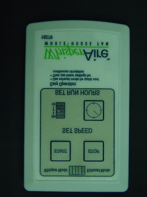
Click to zoom
Application Details
- Equipment Class
- DSC - Part 15 Security/Remote Control Transmitter
- Date of Grant
- Jan 15, 2006
- Application Purpose
- Original Equipment
- Date of Application
- Jan 15, 2006
- Equipment Note
- WHISPER AIRE WHSP2000
- Frequency Range
- 315.00000000 - 315.00000000
- Company
- Air Vent, Inc.
- Country
- United States
Documents & Files
Document Text
Text extracted from the exhibit documents filed with the FCC. Open a document above to read the original.
Users Manual
CONTENTS 1Safety Information 1Tools and Materials Needed 1Optional Tools & Materials 1FCC Requirements 1Operating Information 2What Comes in the Carton 2Step-by-Step Installation 3Attic Ventilation Requirements 3 Electrical Requirements 3 5-Year Limited Warranty 4Replacement Plus™ Protection 4 Operating Instructions 4 WHSP2000 Specifications 4 WHSP2000 Troubleshooting Guide READ AND SAVE THESE INSTRUCTIONS SAFETY INFORMATION Read the following safety information before installing this Whole House Attic Fan. Failure to follow these instructions could result in personal injury or property damage. If you need assistance in under- standing these instructions or have questions or comments, please call 309-692-6969. WARNING– TO REDUCE THE RISK OF FIRE OR ELECTRIC SHOCK, DO NOT USE THIS FAN WITH ANY SOLID-STATE SPEED CONTROL DEVICE OTHER THAN THOSE INCLUDED WITH THE PRODUCT OR AVAIL- ABLE AS AN OPTIONAL CONTROLLER SPECIFICALLY MANUFACTURED FOR THIS PRODUCT. WARNING– TO REDUCE THE RISK OF FIRE, ELECTRIC SHOCK, OR INJURY TO PERSONS, OBSERVE THE FOLLOWING: Use this unit only in the manner intended by the manufacturer. If you have questions, contact the manufacturer. Before servicing or cleaning the unit, switch power off at service panel and lock the ser- vice disconnecting means to prevent power from being switched on accidentally. When the service disconnecting means cannot be locked, securely fasten a prominent warning device, such as a tag, to the service panel. CAUTION– FOR GENERAL VENTILATING USE ONLY. DO NOT USE TO EXHAUST HAZARDOUS OR EXPLOSIVE MATERIALS AND VAPORS. CAUTION– THIS UNIT HAS AN UNGUARD- ED IMPELLER DURING OPERATION. DO NOT USE IN LOCATIONS READILY ACCESSIBLE TO PEOPLE OR ANIMALS. WARNING– TO REDUCE THE RISK OF FIRE, ELECTRIC SHOCK, OR INJURY TO PERSONS, OBSERVE THE FOLLOWING: Qualified person(s) in accordance with all applicable codes and standards, including fire-rated construction, must do installation work and electrical wiring. Sufficient air is needed for proper combustion and exhausting of gases through the flue (chimney) of fuel burning equipment to prevent back drafting. Follow the heating equipment manufacturer’s guideline and safety standards such as those published by the National Fire Protection Association (NFPA), and the American Society for Heating, Refrigeration, and Air Conditioning Engineers (ASHRAE), and the local code authorities. When cutting or drilling into wall or ceiling, do not damage electrical wiring and other hidden utilities. Ducted fans must always be vented to the outdoors. DO NOT install this unit over a tub or shower. NEVER place a switch where it can be reached from a tub or shower. • • • • • • • • FCC REQUIREMENTS THIS DEVICE COMPLIES WITH PART 15 OF THE FCC RULES. FCC ID: NGQGLD001 Operation is subject to the following two conditions: This device may cause harmful interference. This device must accept any interference received, including interference that may cause undesired operation. OPERATING INFORMATION Keep screened windows and/or doors open when the fan is operating to avoid drawing carbon monoxide from furnace and water heater flues and extinguishing pilot lights of appliances. During hot weather requiring air conditioning, when outside air is cooler than indoors, cool the house quicker by first operating the whole house fan for approximately 10 minutes. Then turn off the fan and turn on the air conditioner. For operation during mild weather conditions (when the use of air conditioning is not required) use “Exhaust” modes to evacuate warm air quickly. Then reduce the speed to lower settings for maintaining whole house ventilation. • • • • • TOOLS AND MATERIALS NEEDED Safety goggles Tape measure or folding ruler Pencil Portable electric drill Small drill bit (1/8-, 3/16-inch, etc.) Heavy gauge (bailing) wire or wire hanger Utility knife or Keyhole saw – for cutting sheet rock Saw for cutting lumber 2X framing lumber (length depends on Step 5) to match cross section dimensions of existing joist Wood screws or nails for framing (minimum 8, see Step 5) 1/4-inch nut driver bit (3) Twist-on electrical wire connectors Screwdriver with Phillips bit (2) 1.5V (AA) batteries Optional Tools and Materials– Code required electrical materials • • • • • • • • • • • • • • • Note:Before you begin the step-by-step installation, read the sections on “Attic Ventilation Requirements” and “Electrical Requirements” on page 3. Whisper Aire WHSP2000 Whole House Attic Fan Installation Instructions ™ Step 4: Cut the hole Using a keyhole saw or utility knife, cut between the four corner locations. Note:If you are cutting from inside the attic, you may first want to cut a hand-sized hole at the center to allow for a place to secure the sheet rock while cutting between the four corners. This should help prevent the face of the sheet rock from tearing below. Step 5: Install the framing members Depending on the ceiling joist spacing, cut 2X lumber to (2) 14 1/2-inch lengths for 16-inch OC joists or (2) 22 1/2-inch lengths for 24-inch OC joists. Note:Verify these lengths with a tape mea- sure before cutting lumber. Using nails or wood screws (not provided), install the framing members between the joists with the inside edge flush with the exposed sheet rock edges.(Illustration C) Optional Step:To help reduce the noise level of the fan in the “Exhaust Mode” (higher speeds), install additional 2X framing lumber above the ceiling joists and framing members to create a box that extends the fan further away from the plane of the ceiling and the grill. Warning: It is critical to ensure that enough clearance is available for the fan (Step 2). In addition, the framed box should be sealed so that attic air can not be drawn into it through the joints. Note:This optional step should help minimize the possibility of blown-in insulation from being carried by the airflow and should also help prevent the insulation from impeding the path of the shutter. If after this step has been…
Text truncated - open the document above for the full version.
ID Label/Location Info
SPEC UNLESS OTHERWISE SPECIFIED DIMENSIONS ARE IN INCHES. THIRD ANGLE PROJECTION SIZE SCALE: A .010 COMMON AXIS TO BE WITHIN CONCENTRICITY BETWEEN DIAMETERS ON A 1 01 1 OF 1 ANGLES: SHEET: 2:1 C:\Documents and Settings\pgrisham\Desktop\18176.SLDPRT CFG: Default DWG NO TBD LABEL - WHSP2000 REV .500 = +.008/-.005 .005 OVER .500 = +.006/-.005 .251 TO .251 = .005 .XXX = .02 IT IS LOANED IS PROHIBITED. APVD CHK 01-10-2006 P. GRISHAM PREP 01-10-2005 P. GRISHAM APVD DATE APVD ANY USE EXCEPT THAT FOR WHICH TRANSMITTER BACK D A L L A S , T E X A S HOLE DIAMETERS: UNDER DIMENSION TOLERENCES: .X = .1 .XX = THE INFORMATION HEREON IS THE PROPERTY OFAIR VENT INC. C:\Documents and Settings\pgrisham\Desktop\18176.SLDDRW 00-00-00 REVISIONS REV DESCRIPTION DATE APVD 1.800 1.700 R.050 TYP.
Test Report
Page 1 of 28 Engineering Test Report No. 35711-01 Measurement of RF Interference from a Whole House Fan, Model WHSP2000 with Super Heterodyne Receiver, Part Number 35486 and Remote Control Transmitter, Part Number 35487 For : Air Vent, Inc. Dallas, TX P.O. No. : 310880 Date Received : October 4, 2005 Date Tested : October 4, 2005 and October 5, 2005 Test Personnel : Mark E. Longinotti, NARTE® Certified EMC Test : Engineer, ATL-0154-E Specification : FCC "Code of Federal Regulations” Title 47 Part 15, Subpart B and Subpart C, Sections 15.207 and 15.231 Test Report By : Mark E. Longinotti NARTE® Certified EMC Test Engineer, ATL-0154-E Approved By : Raymond J. Klouda Registered Professional Engineer of Illinois - 44894 Elite Electronic Engineering Inc. 1516 Centre Circle Downers Grove, IL 60515 Tel : (630) 495-9770 Fax: (630) 495-9785 www.elitetest.com Engineering Test Report No. 35711-01 THIS REPORT SHALL NOT BE REPRODUCED, EXCEPT IN FULL, WITHOUT THE WRITTEN APPROVAL OF ELITE ELECTRONIC ENGINEERING INCORPORATED. Page 2 of 28 TABLE OF CONTENTS PARAGRAPH DESCRIPTION OF CONTENTS PAGE NO. 1.0 INTRODUCTION ................................................................................................................................................ 3 1.1 Description of Test Item.................................................................................................................................... 3 1.2 Purpose ............................................................................................................................................................. 3 1.3 Deviations, Additions and Exclusions ............................................................................................................... 3 1.4 Applicable Documents ...................................................................................................................................... 3 1.5 Subcontractor Identification .............................................................................................................................. 3 1.6 Laboratory Conditions..................................................................................................................................... 3 2.0 TEST ITEM SETUP AND OPERATION............................................................................................................. 3 2.1 Power Input...................................................................................................................................................... 4 2.2 Grounding......................................................................................................................................................... 4 2.3 Peripheral Equipment........................................................................................................................................ 4 2.4 Interconnect Cables........................................................................................................................................... 4 2.5 Operational Mode ............................................................................................................................................. 4 2.6 Test Item Modifications................................................................................................................................... 4 3.0 TEST EQUIPMENT............................................................................................................................................. 4 3.1 Test Equipment List .......................................................................................................................................... 4 3.2 Calibration Traceability ................................................................................................................................... 4 3.3 Measurement Uncertainty................................................................................................................................ 4 4.0 REQUIREMENTS, PROCEDURES AND RESULTS.......................................................................................... 5 4.1 Powerline Conducted Emissions ..................................................................................................................... 5 4.1.1 Receiver.................................................................................................................................................... 5 4.1.1.1 Requirements .................................................................................................................................... 5 4.1.1.2 Procedures......................................................................................................................................... 5 4.1.1.3 Results............................................................................................................................................... 6 4.1.2 Transmitter ............................................................................................................................................... 6 4.1.2.1 Requirements .................................................................................................................................... 6 4.2 Duty Cycle Factor Measurements (Transmitter) ............................................................................................ 6 4.2.1 Procedures ............................................................................................................................................... 6 4.2.2 Results ..................................................................................................................................................... 6 4.3 Radiated Measurements................................................................................................................................... 6 4.3.1 Receiver...................................................................................…
Text truncated - open the document above for the full version.
Test Setup Photos
Figure 2 Test Setup for Conducted Emissions Figure 3a Receive at 315MHz Test Setup for Radiated Emissions, 30MHz to 1GHz – Horizontal Polarization Test Setup for Radiated Emissions, 30MHz to 1GHz – Vertical Polarization Figure 3b Transmit at 315MHz Test Setup for Radiated Emissions 315MHz – Horizontal Polarization Test Setup for Radiated Emissions 908.4MHz – Vertical Polarization Figure 3c Transmit at 315MHz Test Setup for Radiated Emissions, 1GHz to 4GHz – Horizontal Polarization Test Setup for Radiated Emissions, 1GHz to 4GHz – Vertical Polarization
Contact Information
Applicant
Brad Holland(Director of Product Development)
Test Firm
Elite Electronic Engineering Co.Daniel Crowder
Technical Specifications
| # | Rule Parts | Frequency Range | Power Output |
|---|---|---|---|
| 1 | 15.231 | 315 MHz - 315 MHz | - |