TSP0B4000CRFID Transceiver
L1 Identity Solutions, Inc.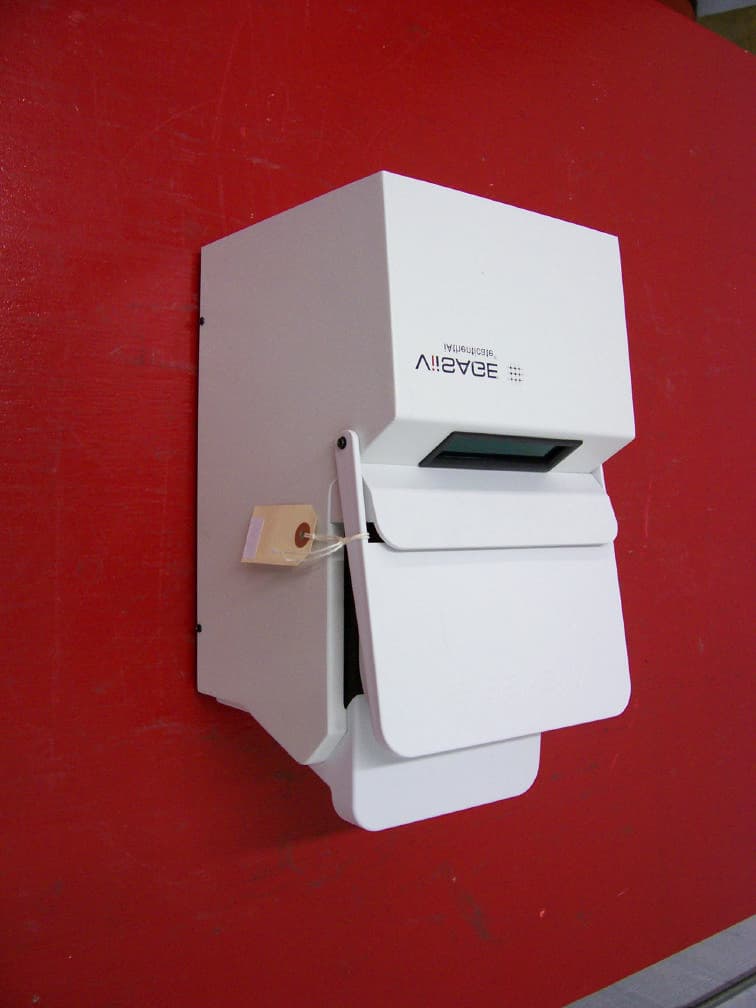
Click to zoom
Application Details
- Equipment Class
- DXX - Part 15 Low Power Communication Device Transmitter
- Date of Grant
- Dec 27, 2005
- Application Purpose
- Original Equipment
- Date of Application
- Dec 27, 2005
- Equipment Note
- RFID Transceiver
- Frequency Range
- 13.56000000 - 13.56000000
- Company
- L1 Identity Solutions, Inc.
- Country
- United States
Documents & Files
Document Text
Text extracted from the exhibit documents filed with the FCC. Open a document above to read the original.
Users Manual
Viisage iA-thenticate ® 4.1 Administrator’s Guide i Viisage iA-thenticate 4.1 Administrator’s Guide ii Copyright 2005 by Viisage Technology, Inc. 296 Concord Road, Billerica, MA 01821 USA Phone 978-932-2200, fax 978-932-2225, web www.viisage.com All rights reserved. Unpublished rights reserved under the copyright laws of the United States. Viisage, the Viisage logo, iA-thenticate, BorderGuard, iA-Passport, iA-DataPort, iA-Examiner, iA-License, TextWatch, and iA-Administrator are trademarks or registered trademarks of Viisage Technology, Inc. All other brand and product names are trademarks or registered trademarks of their respective companies or organizations. Covered by one or more U.S. and foreign patents including U.S. Patent No. 6,269,169. This equipment has been tested and found to comply with the limits for a Class A digital device, pursuant to Part 15 of the FCC Rules. These limits are designed to provide reasonable protection against harmful interference when the equipment is operated in a commercial environment. This equipment generates, uses, and can radiate radio frequency energy and, if not installed and used in accordance with the instruction manual, may cause harmful interference to radio communications. Operation of this equipment in a residential area is likely to cause harmful interference in which the user will be required to correct the interference at his own expense. Changes or modifications not expressly approved by Viisage for compliance could void the user’s authority to operate the device. Safety Guidelines: Follow these safety guidelines to protect your iA-thenticate system from damage and to ensure your own safety. WARNING: Do not attempt to disassemble the iA-thenticate unit or to operate it with any parts removed. The unit contains no user-serviceable parts. Operate iA-thenticate only in an area where the temperature is between 50° F and 105° F (between 10° C and 40° C). Do not spill food or liquids on the iA-thenticate unit. If the unit gets wet, immediately shut down the system and contact Viisage. Do not attempt to open the unit. Only a qualified iA-thenticate technician should perform service and repair work. Do not set anything on top of the iA-thenticate unit or cables. Route all cables so that people will not step or trip on them. Use a surge-protection power strip to protect iA-thenticate against electrical damage, as you would with any computer. The information contained in this document is subject to change without notice. Viisage assumes no responsibility for technical or editorial errors or omissions, or for the use of this material. Nor does Viisage make any commitment to update the information contained in this document. This document contains proprietary information that is protected by copyright. All rights reserved. No part of this document may be photocopied or reproduced in any form without the prior written consent of Viisage. Edition: IA-ADMIN-4.1, 12/05 Publication number: PUB-00052-A-11 iii Table of Contents Part One Setting Up a New iA-thenticate Unit 1 Introduction to iA-thenticate .............................................. 1-1 Hardware Configurations......................................................................................1-1 Basic Setup Options................................................................................................1-2 Full-Featured Document Security Workstation.....................................1-2 Compact, Self-Contained Unit....................................................................1-2 Setting Up iA-thenticate.......................................................................................1-3 2 Setting Up Standard Monochrome iA-thenticate .............. 2-1 PC System Requirements for a Monochrome Unit........................................2-1 Installing Software..................................................................................................2-2 Setting the PC’s Taskbar and Display Properties....................................2-2 Installing the iA-thenticate Security Software......................................2-3 Installing iA-Administrator..........................................................................2-3 Installing iA-Examiner ...................................................................................2-3 Installing the Custom Calibration File......................................................2-4 Installing Optional Software.......................................................................2-4 Installing Hardware................................................................................................2-4 Installing the PCI Card..................................................................................2-4 Connecting the iA-thenticate Cables.......................................................2-5 Finishing Installation..............................................................................................2-6 Starting Up and Checking Installation.....................................................2-6 Configuring Internet Explorer.....................................................................2-7 Configuring a French Version of Windows..............................................2-7 Controlling Access...................................................................................................2-8 Creating Local User Groups and Users ......................................................2-8 Assigning File and Folder Permissions......................................................2-9 Installing a Bar Code and Magstripe Reader................................................ 2-10 What’s Next? .......................................................................................................... 2-10 iv 3 Setting Up Standard Color iA-thenticate........................... 3-1 PC System Requirements for a Color Unit....................................................... 3-1 Software Installation......…
Text truncated - open the document above for the full version.
ID Label/Location Info
Viisage Technology Inc. ï www.viisage.com 296 Concord Road, Billerica, MA 01821 USA MADE IN USA Covered by one or more U.S. and foreign patents including U.S. Patent No. 6,269,169. Barcode area 128 combined model # and serial # 191028 +5 / ñ12 / +12 V 0.85/ 0.1/ 1.4 A MODEL # B4000-C SERIAL # 03-00001 FCC ID: TSP0B4000C BorderGuardóColor This device complies with Part 15 of the FCC Rules. Operation is subject to the following two conditions: (1) This device may not cause harmful interference and (2) This device must accept any interference received, including interference that may cause undesired operation.
Test Report
RETLIF TESTING LABORATORIES TEST REPORT R-4519N1 December 21, 2005 FCC COMPLIANCE TEST REPORT ON Viisage Technology iA-thenticate Borderguard Passport Reader With Integrated 13.56MHz RFID Smart Card Readers FCC ID: TSP0B4000C Test Report No. R-4519N1 FCC ID:TSP0B4000C APPLICANT Viisage Technology 296 Concord Road, 3 Floor rd Billerica, MA 01821 MANUFACTURER SAME TEST SPECIFICATION: FCC Rules and Regulations Part 15, Subpart C, Para. 15.209 TEST PROCEDURE: ANSI C63.4:2001 TEST SAMPLE DESCRIPTION BRANDNAME: iA-thenticate MODEL: B4000-C TYPE: Borderguard Passport Reader With Integrated Dual 13.56MHz RFID Smart Card Readers POWER REQUIREMENTS: 120VAC, 60Hz FREQUENCY OF OPERATION: 13.56MHz FCC ID: TSP0B4000C APPLICABLE RULE SECTION: Part 15, Subpart C, Section 15.209 TESTS PERFORMED 15.209/15.205 Fundamental, Spurious & Restricted Band/Bandedge Emissions 15.207 (a) AC Line Conducted Emissions TEST SAMPLE DESCRIPTION The EUT is a Passport Reader with dual 13.56MHz RFID Smart Card Readers. The Borderguard Passport Reader is used to read new style passports containing data chips embedded in the front and/or back pages of the passport. The Passport Reader contains two identical 13.56MHz RFID Card Readers (top and front/bottom). Two Readers are necessary in order to read two different types of passports which be may be used (different data chip locations in the passport). Depending on the location of the data chip within the passport either the top or front/bottom RFID card reader will be activated and the other one will be disabled by software so that only one of the readers will be active (transmitting) at any given time. During normal use the Passport reader is connected to a host PC and receives power through the AC mains (120VAC, 60Hz). The Borderguard Passport Reader has also been tested and found to be compliant with Part 15, Subpart B as a computer peripheral/digital device and a separate test report issued. Test Report No. R-4519N1 FCC ID:TSP0B4000C ANTENNA DESCRIPTION Each Card Reader has an integral antenna and thus the EUT had no external antenna/antenna ports. TEST SAMPLE / TEST RESULTS SUMMARY 15.205RESTRICTED BANDS OF OPERATION No emissions from the EUT were observed in any of the restricted bands. As the 13.56MHz frequency of operation falls near the restricted band of 13.36 to 13.41MHz compliance at the band edge of the restricted band was verified at worst case operating mode (see attached data) 15.207CONDUCTED EMISSIONS No emissions above the limit specified in 15.207(a) was observed in any operating condition. Worst case emissions were observed in search/toggle mode and this data is included in this application (See attached) 15.209RADIATED EMISSIONS Fundamental Frequency 13.56MHz Out of Band, Spurious, Harmonics 9kHz - 1000MHz Field Strength Limits: Fundamental Frequency: 13.56MHz The maximum permitted fundamental field strength at 30 meters is 30uV/M = 29.5dBuV: Unwanted emissions cannot exceed the level of the fundamental emissions. RADIATED EMISSIONS TEST RESULTS The maximized peak field strength at 13.56MHz was below the limit specified in 15.209. The test sample was tested in 3 operating conditions (top reader active, front/bottom reader active and search/toggle mode in which each card reader is activated back and forth in turn while searching for a valid passport). The worst case fundamental emission at 13.56MHz was found to occur during search/toggle mode where the maximized emission was 3dB below the specified limit. Test data is included for this worst case operating condition. No harmonic or transmitter spurious emissions were observed at 1 or 3 meter test distances in any of the 3 operating conditions. Bandedge Compliance in the 13.36 to 13.41MHz restricted band was also verified at worst case operating mode (see attached plot). CONDUCTED EMISSIONS TEST RESULTS The AC line conducted emissions met the limit specified in 15.207 (a) in all three operating conditions. Worst case emissions were observed in search/toggle mode. Data is included for this worst case mode. (See attached) Test Report No. R-4519N1 FCC ID:TSP0B4000C MEASUREMENT PROCEDURES 15.209 Field Strength of Fundamental, Harmonic/Spurious and Band Edge Emissions The field strength of the fundamental, harmonic/spurious and bandedge emissions were measured. The EUT and support equipment were placed on a 80cm high wooden test stand which was located 3 meters from the test antenna on an FCC listed open area test site. Emissions from the EUT were maximized by rotating the test sample and adjusting the test sample cabling and antenna polarization. The maximized field strength of each observed emission was measured, recorded and compared to the specified limits of 15.209. Bandedge measurements were made to verify compliance in 13.36 to 13.41MHz restricted band. When necessary the marker/delta method was used to verify bandedge compliance. 15.207 AC Line Conducted Emissions The EUT and support equipment were placed on a 0.8m high wooden test stand above the floor of the test area (ground plane). The rear of the test sample was aligned flush with the rear of the test stand. The test stand was situated such that the test sample was located 0.4m from all other grounded surfaces. The power cord of the test sample was connected to an artificial mains network (LISN). The spectrum analyzer was connected to the RF port of the LISN and measurements were taken in the frequency range of 150kHz to 30MHz on each the hot and neutral leads. Emissions were evaluated in all three operating conditions (top reader active, front/bottom reader active, search/toggle). Test Report No. R-4519N1 FCC ID:TSP0B4000C TEST EQUIPMENT LISTS FUNDAMENTAL & SPURIOUS EMISSIONS ENTypeManufacturerDescriptionModel No.Cal DateDue 3207Loop AntennaEMCO10 KHz - 30 MHz650207/22/200507/22/2006 4202BiconilogEMCO26 MHz - 2 GHz314212/13/200412/13/2005 713EMI Test ReceiverRohde & Schwarz20 Hz - 26.5 GHzESI2603/22/200503/22/2006 AC LINE CONDUCTED EMISSIONS ENTypeM…
Text truncated - open the document above for the full version.
Test Setup Photos
Test Report No. R-4519N1 FCC ID:TSP04B000C RADIATED EMISSIONS TEST SETUP PHOTOGRAPH 9kHz to 30MHz Test Report No. R-4519N1 FCC ID:TSP04B000C RADIATED EMISSIONS TEST SETUP PHOTOGRAPH 30MHz to 1GHz CONDUCTED EMISSIONS SETUP PHOTOGRAPH .15 to 30MHz
Contact Information
Applicant
Jim Queenan(Director of Hardware Engineering)
Technical Contact
Retlif Testing LaboratoriesScott Wentworth
[email protected]603-497-4600
101 New Boston Road · Goffstown, New Hampshire · United States
Non-Technical Contact
Retlif Testing LaboratoriesScott Wentworth
[email protected]603-497-4600
Test Firm
Retlif Testing LaboratoriesScott Wentworth
Technical Specifications
| # | Rule Parts | Frequency Range | Power Output |
|---|---|---|---|
| 1 | 15C | 13.56 MHz - 13.56 MHz | - |
Other Applications from L1 Identity Solutions, Inc.

TSP0B5000B
Jan 23, 2012B5000B IS A DOCUMENT AUTHENTICATION SYSTEM WITH RFID SMART CARD CAPABILITY AND OPTIONAL FINGERPRINT READER
Equipment Class
DXX - Part 15 Low Power Communication Device Transmitter
TSP0B5000A
Jan 06, 2008BORDERGUARD WITH SMART CHIP, DOCUMENT SCANNER MODE
Equipment Class
DXX - Part 15 Low Power Communication Device Transmitter