TSQ-QUIKFLAGREMOTE CONTROL LIGHT SYSTEM
Theatronix
Click to zoom
Application Details
- Equipment Class
- DSC - Part 15 Security/Remote Control Transmitter
- Date of Grant
- Dec 11, 2005
- Application Purpose
- Original Equipment
- Date of Application
- Dec 11, 2005
- Equipment Note
- REMOTE CONTROL LIGHT SYSTEM
- Frequency Range
- 418.00000000 - 419.00000000
- Company
- Theatronix
- Country
- United States
Documents & Files
Document Text
Text extracted from the exhibit documents filed with the FCC. Open a document above to read the original.
Users Manual
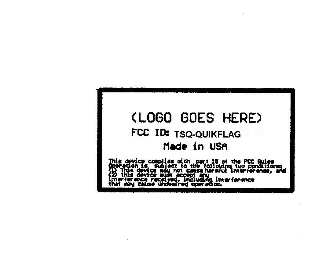
REMOTE CONTROL LIGHT SYSTEM INSTALLATION & OPERATION 11/15/05 INSTALLATION 1] Mount the transmitter module on the back of the truck. A high mounting spot is preferable with the antenna vertical. The antenna should not be right next to a metal surface for best range, but usually this isn't critical. 2] Run the cable from the truck lights to the transmitter module. (If the cable does not plug into a trailer connector, use the following color code:) RED Strobe Enable. The yellow strobes flash if this is tied to +12VDC. A switch in the cab can be used to enable the strobes, or the wire can be tied to an existing switch for top-of-cab strobes. WHITE Tail lights. ORANGE Brake wire (if it is separate from turn signals. If the brake and turn signals are the same lights, leave this one unhooked, and tape it up.) GREEN Left turn signal. BLUE Right turn signal. BLACK Frame ground. 3] Wire the battery charger cables to a continuous source of 12VDC, fused at not under 4 amps, and not over 15 amps. The charger cords must reach to the location you store the light bars. The BLACK wire is +, and the WHITE wire is GROUND. 4] Tune the Quik-Flag bar to your transmitter. Each bar comes preset to a "dummy" address. Therefore it won't work with the transmitter you just installed until the address is properly selected. To tune it to your transmitter, turn on your turn signals, then plug in the charger. When the green charge light has flashed once or twice, place a magnet over the marked spot on the receiver box, then with the magnet in place, unplug the charger cord. You will get the usual end-of-charge signal, and a continuous side-light on the bar. Remove the magnet. The side-light will go out, and the bar will "listen" to your turn signals flashing for a few seconds, then, if it was able to get a good address, it will flash the brake and strobe back and forth for several seconds rapidly. After that it is tuned to your system. If there was a lot of RF noise, and it couldn't verify the address, it will flash the brake several times, slowly. In that case, try again. If you still can't get a good address, move to a different location that might have less RF hash, or maybe turn off nearby fluorescent lights, which can sometimes cause hash. OPERATION 1] The light bars have no ON/OFF switch. When not in use, leave them plugged into the battery charger. This shuts them off, stopping the strobe and shutting off the lights. The bars will not overcharge, and will drop to a trickle-charge after the battery pack is full. The green light on the receiver box is on when fast- charging. It flicks off once every 4 seconds or so. If in storage for a while (not being charged), you need to charge them overnight before use. 2] When you unplug the charger cord from the Quik-Flag bar, the LEDs will flash in a pattern to let you know the battery condition. About 1 second will elapse before the signals are given, then the pattern will be repeated twice, a couple of seconds apart. NORMAL END OF CHARGE, DISCONNECTED BEFORE IT WAS FULL 1 GREEN PULSE NORMAL END OF CHARGE, BATTERY IS FULL UP. NOTE: Which type of termination depends on battery temperature. Either is OK. 2 GREEN PULSES IF CHARGE IS COMPLETE, VOLTAGE SLOPE 1 RED 1 GREEN PULSE IF CHARGE IS COMPLETE, TEMP SLOPE TROUBLE SIGNALS. 4 YELLOW PULSES IF BATTERY IS TOO HOT TO CHARGE (approx 130 F) (cool off the battery pack, then try again. If it cools off while the charger is still plugged in, it will automatically start charging after a few minutes.) 2 GREEN PULSES + 1 RED PULSE IF CHARGER IS TIMED OUT (it kept charging longer than it should need to fill the battery) 2 YELLOW, 2 RED PULSES IF OVERVOLTAGE (open battery) 3 YELLOW, 3 RED PULSES IF OVERVOLTAGE (weak battery) 3] To use, unplug the bars from the charger and mount them on the mobile home. They will turn themselves on when you turn on any light on the truck. Be sure to put the charge cord caps back on! You don't want the connectors full of mud. 4] NOTE #2: The strobes are designed so that they will flash in a synchronized pattern. This is set when the strobes are activated. If one bar is plugged into the charger circuit and the other bar is not, the strobes will activate on one bar, but not the other one. When the other bar is unplugged from the charger, and brake or turn signal is activated, the strobes on this bar will turn on, but will NOT synchronize with the first bar. To re-sync, just turn the strobes off, tap the brake, then turn them back on. MAINTAINANCE 1] Battery Care: The NIMH battery pack should last for several years of normal usage. No special care is needed. If the Quik-Flag bar isn't used or charged for several days, recharge it before use. NIMH batteries do self- discharge slowly, and the microprocessor and radio receiver run continously. If the battery pack is completely run down, recharge will take up to 13 hours for a full charge, but the units can be used again with partial charge. A new battery pack is good for at least 24 hours with the strobes and the taillights on, and will probably last for almost 50 hours. FCC NOTICES: NOTE: Changes or modifications not expressly approved by the manufacturer could void the user's authority to operate the equipment. This device complies with part 15 of the FCC Rules. Operation is subject to the following two conditions: (1) This device may not cause harmful interference, and (2) this device must accept any interference received, including interference that may cause undesired operation.
Cover Letter(s)
Rev. 1/1/03 3340 Liberty Rd. Dallas, OR 97338 503-623-6551 Federal Communications Commission Authorization and Evaluation Division Confidentiality Request regarding application for certification of FCC ID: TSQQUIK-FLAG Pursuant to Sections 0.457 and 0.459 of the Commission’s Rules, we hereby request confidential treatment of information accompanying this application as outlined below: ALL SCHEMATICS The above materials contain trade secrets and proprietary information not customarily released to the public. The public disclosure of these materials may be harmful to the applicant and provide unjustified benefits to its competitors. The applicant understands that pursuant to Section 0.457 of the Rules, disclosure of this application and all accompanying documentation will not be made before the date of the Grant for this application. Sincerely, Douglas Hartell
External Photos
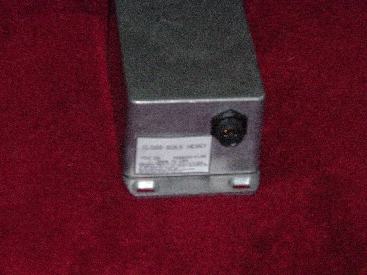
THEATRONIX FCC ID: TSQQUIK-FLAG EXTERNAL PHOTOS
Internal Photos
THEATRONIX FCC ID: TSQQUIK-FLAG INTERNAL PHOTOS
Operational Description
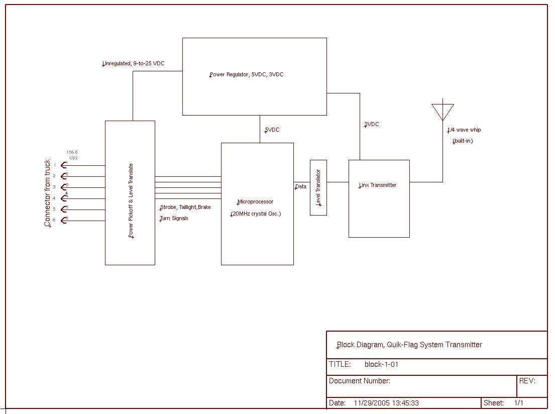
Quik-Flag System Circuit description: The Quik-Flag System is a wireless light system for mobile home transporters. The lights on the back of the mobile home are mounted on an aluminum frame which fastens to the mobile home with either a hook on the roof or screws into the corner of the building. It contains [a] lights (LED type), [b] a battery pack, and [c] a radio receiver and microprocessor. The matching transmitter is mounted on the truck with wires running to the various lights—brake, strobes, running lights, turn signals (L and R). When any of these wires is pulled to 12VDC by turning on the light associated with it, the transmitter sends a brief coded burst of data to the receiver, which decodes the data and turns on the light. When the light on the truck is turned back off, another coded burst is sent to the receiver. The transmitter never does continuous broadcasting. The coding scheme is a 7-byte string consisting of a 2-byte header, a 3-byte address, and 2 bytes of data to select which lights are on. The data is sent at 4800 baud, with small delays between bytes to keep the overall average transmission power level down. Each data string is sent 3 times for security. The transmitter circuit consists of : [a]A level converter and power pickoff section that converts the 12VDC levels of input into 5VDC inverted signals to the microprocessor. It also sends some of the power to a large capacitor which stores it for powering the turn-off data burst when the light is turned off. [b] The voltage regulation section. The 12VDC stored on the capacitor is regulated first to 5VDC for the microprocessor, then sent through a further regulator for the 3VDC needed on the transmitter module. [c] The microprocessor, a Microchip PIC15F88, running at 20MHz, crystal controlled. [d] The radio module, a Linx -LR series transmitter. The frequency is 418MHz, OOK modulation. A single resistor controls the power output. (For testing, this resistor has been replaced with a trim pot, which will be replaced with the correct value of fixed resistor in production.) [e] The antenna. It is bolted into the case with a pipe fitting so that it cannot be replaced with another type of antenna. It is a ¼-wave whip. The receiver consists of: [a] The ¼ wave whip antenna, removable. [b] The Linx -LR receiver module. [c] The PIC16F88 microprocessor. It runs at 20MHz, crystal controlled. [d] The power regulator. It takes the 12VDC from the battery pack and converts it to 5VDC for the microprocessor. The Linx receiver is powered through a series resistor to drop it to about 3VDC. [e] The output driver transistors. These 3 power transistors control the actual lights. They will be PWM controlled to run the brake light at running-light brightness. [f] The battery charger circuit. It consists of a buck/boost regulator, current limited, controlled by the microprocessor. Any charging voltage from 7 to 18 is permitted. When charging voltage is present, the receiver unit ignores the radio signals, and turns off all the lights. When the charging voltage is removed, it flashes the lights in a pattern representing the battery condition. When the receiver picks up a signal, it checks it for the correct address , and verifies that the “normal” and “inverted” bytes match each other. If not, it discards the entire data string. If it is accurate, it sets the lights in the proper pattern to match the data. A single jumper on the board determines whether the board is a left-hand or right-hand controller. A magnetic switch on the board, activated through the case with a magnet, allows the receiver's address to be changed to match the transmitter.
Test Report
TIMCO ENGINEERING INC. 849 NW State Road 45 Newberry, Florida 32669 http://www.timcoengr.com 888.472.2424 F 352.472.2030 email: [email protected] APPLICANT: THEATRONIX FCC ID: TQSQUIK-FLAG Test Report Product Name: SECURITY DEVICE TRANSMITTER FCC ID: TSQ-QUIKFLAG Applicant: THEATRONIX 3340 LIBERTY ROAD DALLAS, OR 97338 Date Receipt: 11/22/2005 Date Tested: 11/23/2005 REPORT #: T\THEATRONIX\2360AUT5\2360AUT5TestReport.doc COVER SHEET TIMCO ENGINEERING INC. 849 NW State Road 45 Newberry, Florida 32669 http://www.timcoengr.com 888.472.2424 F 352.472.2030 email: [email protected] APPLICANT: THEATRONIX FCC ID: TSQ-QUIKFLAG TABLE OF CONTENTS APPLICANT: THEATRONIX FCC ID: TSQ-QUIKFLAG TEST REPORT CONTAINING: PAGE 1.............TEST EQUIPMENT LIST PAGE 2.............TEST PROCEDURE PAGE 3-4...........RADIATION INTERFERENCE TEST DATA PAGE 5.............CALCULATION OF DUTY CYCLE PAGE 6-7...........DUTY CYCLE PLOTS PAGE 8-9...........OCCUPIED BANDWIDTH EXHIBIT INCLUDING: CONFIDENTIALITY REQUEST LETTER BLOCK DIAGRAM SCHEMATIC PARTS LIST INSTRUCTION MANUAL LABEL SAMPLE LABEL LOCATION EXTERNAL PHOTOGRAPHS INTERNAL PHOTOGRAPHS OPERATIONAL DESCRIPTION TEST SET UP PHOTOGRAPH REPORT #: T\THEATRONIX\2360AUT5\2360AUT5TestReport.doc TABLE OF CONTENTS TIMCO ENGINEERING INC. 849 NW State Road 45 Newberry, Florida 32669 http://www.timcoengr.com 888.472.2424 F 352.472.2030 email: [email protected] APPLICANT: THEATRONIX FCC ID: TSQ-QUIKFLAG EMC Equipment List Device Manufacturer Model Serial Number Cal/Char Date Due Date 3/10-Meter OATS TEI N/A N/A Listed 3/27/04 3/26/07 3-Meter OATS TEI N/A N/A Listed 1/13/03 1/12/06 Biconnical Antenna Eaton 94455-1 1096 CAL 8/17/04 8/17/06 Biconnical Antenna Electro- Metrics BIA-25 1171 CAL 4/29/05 4/29/07 Blue Tower Quasi-Peak Adapter HP 85650A 2811A01279 CAL 4/13/05 4/13/07 Blue Tower RF Preselector HP 85685A 2926A00983 CAL 8/3/05 8/3/07 Blue Tower Spectrum Analyzer HP 8568B 2928A04729 2848A18049 CAL 4/13/05 4/13/07 Double- Ridged Horn Antenna Electro- Metrics RGA-180 2319 CAL 12/29/04 12/29/06 LISN Electro- Metrics ANS-25/2 2604 CAL 8/27/04 8/27/06 LISN Electro- Metrics EM-7820 2682 CAL 4/28/05 4/28/07 REPORT #: T\THEATRONIX\2360AUT5\2360AUT5TestReport.doc Page 1 of 9 TIMCO ENGINEERING INC. 849 NW State Road 45 Newberry, Florida 32669 http://www.timcoengr.com 888.472.2424 F 352.472.2030 email: [email protected] APPLICANT: THEATRONIX FCC ID: TSQ-QUIKFLAG TEST PROCEDURE GENERAL: This report shall NOT be reproduced except in full without the written approval of TIMCO ENGINEERING, INC. RADIATION INTERFERENCE: The test procedure used was ANSI STANDARD C63.4-2003 using a HEWLETT PACKARD spectrum analyzer with a preselector. The bandwidth of the spectrum analyzer was 100 kHz with an appropriate sweep speed. The analyzer was calibrated in dB above a microvolt at the output of the antenna. The resolution bandwidth was 100 kHz and the video bandwidth was 300 kHz. The ambient temperature of the UUT was 98.3ºF with a humidity of 40%. FORMULA OF CONVERSION FACTORS: The Field Strength at 3m was established by adding the meter reading of the spectrum analyzer (which is set to read in units of dBuV) to the antenna correction factor supplied by the antenna manufacturer. The antenna correction factors are stated in terms of dB. The gain of the Preselector was accounted for in the Spectrum Analyzer Meter Reading. Example: Freq (MHz) METER READING + ACF = FS 33 20 dBuV + 10.36 dB = 30.36 dBuV/m @ 3m ANSI STANDARD C63.4-2003 10.1.7 MEASUREMENT PROCEDURES: The UUT was placed on a table 80 cm high and with dimensions of 1m by 1.5m. The UUT was placed in the center of the table. The table used for radiated measurements is capable of continuous rotation. The spectrum was scanned from 30 MHz to 10th harmonic of the fundamental. Peak readings were taken in three (3) orthogonal planes and the highest readings were converted to average readings based on the duration of "ON" time. When an emission was found, the table was rotated to produce the maximum signal strength. At this point, the antenna was raised and lowered from 1m to 4m. The antenna was placed in both the horizontal and vertical planes. Measurements were made by TIMCO ENGINEERING INC. at the registered open field test site located at 849 N.W. State Road 45, Newberry, Fl 32669. REPORT #: T\THEATRONIX\2360AUT5\2360AUT5TestReport.doc Page 2 of 9 TIMCO ENGINEERING INC. 849 NW State Road 45 Newberry, Florida 32669 http://www.timcoengr.com 888.472.2424 F 352.472.2030 email: [email protected] APPLICANT: THEATRONIX FCC ID: TSQ-QUIKFLAG APPLICANT: THEATRONIX FCC ID: TSQ-QUIKFLAG NAME OF TEST: RADIATION INTERFERENCE RULES PART NO.: 15.231 REQUIREMENTS: Fundamental Field Strength Field Strength of Frequency of Fundamental Harmonics and Spurious MHz dBuV Emissions (dBuV/m @ 3m) 40.66 to 40.70 67.04 47.04 70 to 130 61.94 41.94 130 to 174 61.94 to 71.48 41.94 to 51.48 174 to 260 71.48 51.48 260 to 470 71.48 to 81.94 51.48 to 61.94 470 and above 81.94 61.94 THE LIMIT FOR AVERAGE FIELD STRENGTH dBuV/m FOR THE FUNDAMENTAL FREQUENCY = 80.28 dBuV/m. NO FUNDAMENTAL IS ALLOWED IN THE RESTRICTED BANDS. THE LIMIT FOR AVERAGE FIELD STRENGTH dBuV/m FOR THE HARMONICS AND SPURIOUS FREQUENCIES = 60.28 dBuV/m. SPURIOUS IN THE RESTRICTED BANDS MUST BE LESS THAN 54 dBuV/m OR 15.209. TEST DATA: Emission Frequency MHz * Meter Reading dBuV Ant. Pol. Coax Loss dB Correction Factor dB Duty Cycle Factor dB Field Strength dBuV/m Margin dB 418.00 62.7 H 3.17 16.26 16.10 66.03 14.25 418.00 75.2 V 3.17 15.98 16.10 78.25 2.03 836.00 11.8 H 4.84 22.78 16.10 23.32 36.97 836.00 14.7 V 4.84 22.74 16.10 26.18 34.11 1,254.00 13.2 V 1.33 28.00 16.10 26.43 33.86 2,090.00 6.7 H 1.74 31.78 16.10 24.12 36.17 2,090.00 7.4 V 1.74 31.78 16.10 24.82 35.47 2,926.00 3.9 H 2.07 33.28 16.10 23.15 37.13 2,926.00 7.7 V 2.07 33.28 16.10 26.95 33.33 REPORT #: T\THEATRONIX\2360AUT5\2360AUT5TestReport.doc Page 3 of 9 TIMCO ENGINEERING INC. 849 NW State Road 45 Newberry, Florida 32669 http://www.timcoengr.com …
Text truncated - open the document above for the full version.
Contact Information
Applicant
Douglas Hartell(consultant/designer)
Test Firm
Timco Engineering, Inc.S Sanders
Technical Specifications
| # | Rule Parts | Frequency Range | Power Output |
|---|---|---|---|
| 1 | 15.231 | 418 MHz - 419 MHz | - |