TTFN01A1206Dual Radio 2.4GHz/5GHz Access Point
eXS Inc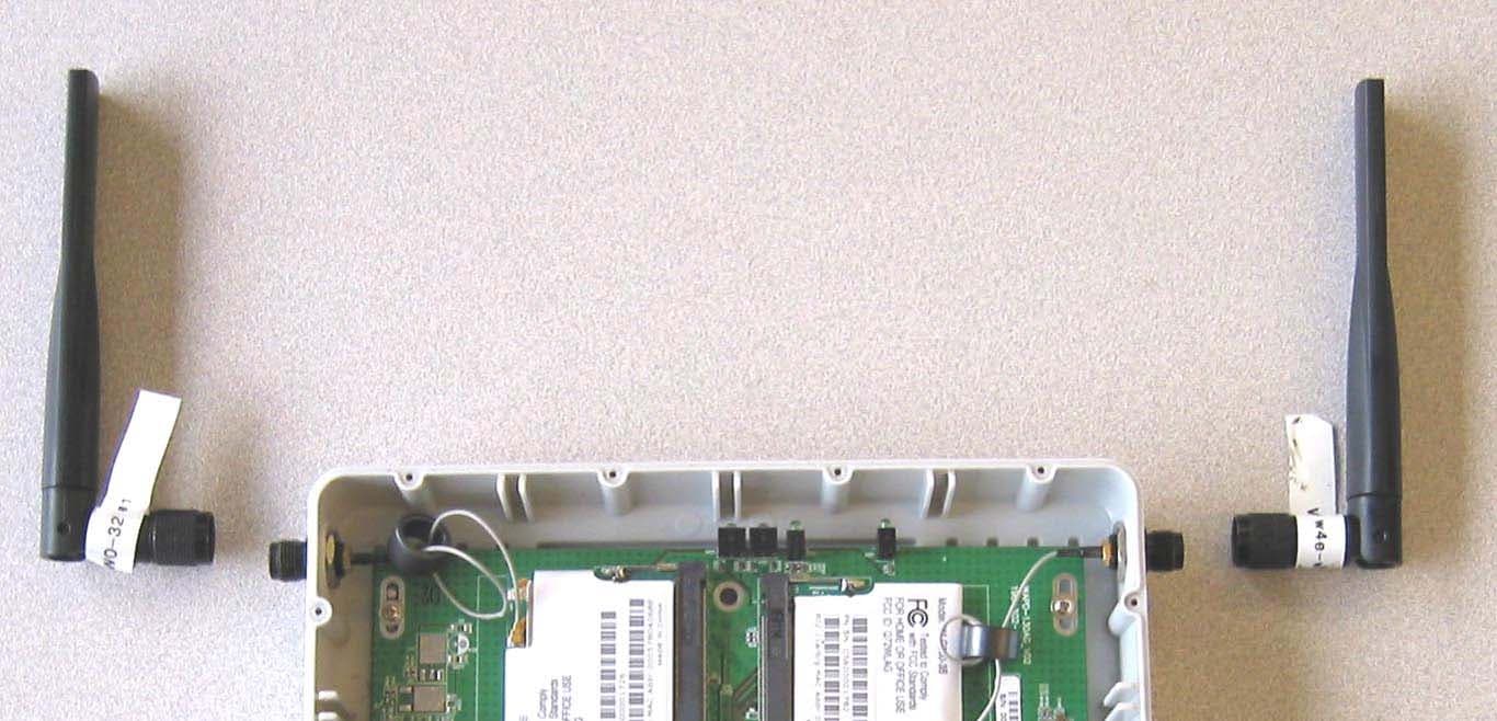
Click to zoom
Application Details
- Equipment Class
- NII - Unlicensed National Information Infrastructure TX
- Date of Grant
- Dec 22, 2005
- Application Purpose
- Original Equipment
- Date of Application
- Dec 22, 2005
- Equipment Note
- Dual Radio 2.4GHz/5GHz Access Point
- Frequency Range
- 5260.00000000 - 5320.00000000
- Company
- eXS Inc
- Country
- Virgin Islands (British)
Documents & Files
Document Text
Text extracted from the exhibit documents filed with the FCC. Open a document above to read the original.
Users Manual
eXS 5001 Wireless NODE Version A Technician Manual Revision A.2.1 November, 2005 ® eXS 5001A Tech Manual 2 Contents CONTENTS................................................................................2 WEB CONFIGURATION MANAGER APPLICATION......................5 Top...............................................................................................................7 Status...........................................................................................................7 Log...............................................................................................................8 Setup............................................................................................................9 Web Configuration Manager Setup Feature......................................................10 IP Addresses and General Network Setup.......................................................10 Wireless Access...........................................................................................13 Wi_Fi Protected Access (WPA-PSK)................................................................15 MAC Address Authentication.........................................................................15 Channel Setup............................................................................................17 Committing Your Changes............................................................................18 Advanced.....................................................................................................18 Wireless Setting for the Access Point..............................................................19 Wireless Setting for the Mesh Network...........................................................19 Network Settings for the NODE.....................................................................20 Network Settings for the Ethernet port...........................................................21 WDS..........................................................................................................23 Traffic control:............................................................................................24 Backup........................................................................................................25 Restore........................................................................................................26 Restoring from Factory Defaults....................................................................27 Restoring from Last Committed Changes........................................................28 Restoring from a Local File............................................................................28 Software Update..........................................................................................31 Using the Update Feature.............................................................................31 Uploading via Web Browser..........................................................................32 Downloading via the http or ftp Protocol.........................................................33 Troubleshooting the Software Update Process..................................................34 Reboot.........................................................................................................34 MULTI-LAYERED MESH NETWORK..........................................35 eXS 5001A Tech Manual 3 COPYRIGHT INFORMATION....................................................36 LIMITED WARRANTY..............................................................36 APPENDIX: RADIO CHARACTERISTICS...................................40 Transmit Output Power................................................................................40 Maximum Output Power Settings, United States..........................................41 Receiver Sensitivity.....................................................................................42 APPENDIX: USER INFORMATION............................................43 Professional Installation..............................................................................43 Operation....................................................................................................43 Interference................................................................................................43 Radiation Exposure......................................................................................44 APPENDIX: FCC RULES...........................................................45 Part 15.203: Antenna Requirement................................................................45 Part 15.407: Technical Requirements (UNII)...................................................45 Part 15.407: RF Transmission Auto-control.....................................................46 eXS 5001A Tech Manual 4 Introduction The eXS® 5001 Wireless NODE is a dual-radio device that enable the network operator to deploy a wireless network, eXS ZONE™, without laying any data cables. The eXS NODE™ is designed to: 1. Mesh with other NODEs using the IEEE 802.11a radio 2. Service clients over the Ethernet port and the wireless access port (IEEE 802.11g radio) 3. The traffic is routed to the eXS NODE™ that is connected to the backhaul, otherwise known as the gateway. The NODE is a layer-3 router that can be configured as a Repeater or as a Gateway. In the Repeater configuration the DHCP server internal to the NODE will service BOTH the LAN port and the wireless 802.11g access. The NODE supports the installation of client devices like a SIP phones over the LAN interface. The Gateway mode will configure the LAN interface to act as a WAN port to enable the unit to interface to the existing campus/corporate LAN or to the available backhaul. The port in this configuration can be configured to act as a DHCP CLIENT or with STATIC IP information. The setup of the 802.11b/g access is performed through the “setup” tab while the mesh network configu…
Text truncated - open the document above for the full version.
Users Manual
Installation Instructions eXS 5001A These instructions cover indoor mounting on a wall or ceiling, as well as outdoor mounting on a wall or a pole. Parts Needed The eXS-5001 Wireless NODE™ installation kit consists of the following items: 1. The eXS-5001 NODE 2. Antennas: 1 for Networking (5GHz) & 1 for Access (2.4GHz) 3. AC/DC power converter with PoE jacks 4. Hardware bag with “T” and RJ-45 weather gasket Items procured locally are: 5. Cat5 cable terminated to the appropriate length, fabricated locally 6. AC power cord purchased locally with a “computer” connector (IEC60320/c13, see photo). Wall Mount The eXS NODE can be mounted indoors on the specified wall as follows. 1. Mark 2 holes 154mm apart. The Mounting Template may help mark these holes. 2. Insert the round-head screws, maximum 4 mm diameter shaft, leaving about 10mm space from the wall to the underside of the screw head. 3. Hang the eXS NODE on these screws. Be sure the NODE is not loose. 4. Be sure both antennas are up & vertical. It there is interference above the NODE, rotate them downward so they are down & vertical. 5. Run a length of Cat5 LAN cable from this location to where the AC/DC converter will be plugged in. Maximum length is 100 meters. The RJ-45 plug should be wired per the diagram. 6. Insert the cable plug into the RJ-45 jack. 7. The cable bushing and cap are generally used only for outdoor installations. 8. Use round-cable staples to hold the cable in place, spacing them about 1 meter apart or as needed. Allow 20-30mm at bends in the cable, to avoid pinching. [Sharp bends in Cat5 cable may cause data errors]. 9. Allow about 150-200mm slack cable at the power converter. 10. Plug the AC/DC converter into the AC outlet. 11. Verify that there is a wireless connection to the Internet before plugging a PC or LAN into the wired jack. Ceiling Mount 1. Install the 2 “T” pieces to the bottom of the NODE, sliding them into the groves until they snap over the bump. 2. Mark & drill the 4 holes. The holes are 54x214mm apart. 3. Mount the eXS NODE using the 4 screws. There is a little slot in the T’s to adjust for holes that are slightly off center. 4. Rotate the antennas 90 degrees so they are down & vertical Pin assignments clip down (TIA568A): 1&2) Transmit Data (green) 3&6) Receive Data (orange) 4&5) Positive DC voltage (blue) 7&8) Negative DC Voltage (brown) AC Power cord LAN to PC, VoIP to eXS NODE 154 mm 4 mm Outdoor Mounting The eXS NODE is weatherproof and can be mounted outdoors. 1. Install the 2 “T” pieces to the bottom of the NODE, sliding them into the groves until they snap over the bump. 2. Mark & drill the 4 holes. The holes are 54x214mm apart. 3. Mount the eXS NODE using the 4 screws. There is a little slot in the T’s to adjust for holes that are slightly off center. 4. Verify that the NODE will not move in the wind. 5. Be sure the 2 antennas are vertical. If there is interference above, rotate them downward. 6. Terminate the PoE cable. The wiring diagram is the same as the indoor installation, but outdoor-rated cabling should be used. 7. Pull the cable connector through the cap and through the weather bushing. 8. Plug the RJ-45 plug into the RJ-45 jack on the housing. 9. Push and twist the weather bushing onto the housing. 10. Tighten the Compression Nut so it is weather-tight. 11. When the cable enters the building, create a “drip loop”. 12. Use round-cable staples to hold the cable in place, spacing them about 1 meter apart. Allow 20-30mm at bends in the cable, to avoid data errors. 13. If the cable is not pre-terminated, cut it to length at the AC/DC converter location. Allow about 150-200mm slack cable. Install the RJ-45 plug. 14. Plug the AC/DC converter into the AC outlet indoors and plug in the Cat5 cable. Pipe Mounting Pipe or pole mounting is accomplished with two straps holding the “T”. For small pipes, a simple hose clamp will work well (e.g., stainless steel, 23-70mm long, 10-14mm wide). For larger utility poles, use the same straps used to mount signs to the poles. Antenna Options On occasion there is a need for other types of antennas. If these have been ordered and assembled, then they will have their own installation instructions. The NODE has icons next to the antenna connectors for the Network and Access ports respectively. Verification Verify that there is a wireless connection to the Internet before attaching PC to the LAN jack. Questions or comments? Please write to: [email protected] All specifications are subject to change without notice. All contents are Copyright © 2004 eXS, Inc. All rights reserved. eXS, eXS ZONE, eXS NODE and their logos are trademarks of eXS, Inc, a BVI company, and/or its affiliates in Malaysia, the U.S. and certain other countries. All other trademarks mentioned in this document are the property of their respective owners. TM-1015-May2005B, part#710-00001A T piece (2) “bump” Hose clamps (top & bottom) Network icon Access icon T with mounting holes 54 mm 214 mm building entrance drip loop round staples
Cover Letter(s)
tel: 650-726-1263 fax: 650-726-1252 [email protected] Thomas N. Cokenias EMC &Radio Approvals Test & Consulting Services for Commercial, Military, International Compliance P.O. Box 1086 El Granada, CA 94018 email: [email protected] Compliance Certification Services 12 December 2005 561F Monterey Road Morgan Hill, CA 95037 Attention: Applications Examiner Re: DTS and U-NII application for eXS Inc. FCC ID: TTFN01A1206 To whom it may concern, My client eXS Inc. has developed a dual band WiFi access point and has applied for certification under sections 15.247 and 15.401 of the FCC Rules. The eXS product is a combination of two previously granted devices: Radio Module Grantee: Chung Nam Electronics Co., Ltd FCC ID: Q72WLAG Grant Date: 10/05/2004 Motherboard Grantee: Gemtek Technology Co., Ltd FCC ID: MXF-AP940422AG Grant Date: 07/20/2005 The radio module is used unchanged. The motherboard section of the Gemtek board is unchanged. eXS replaced the Gemtek radio card with the Chung Nam card, and uses a different antenna from the one used by Gemtek. Lastly, the DC power to the product is provided via a power over Ethernet (POE) module supplied separately. The eXS product is professionally installed, is sold only through the eXS distribution system and is not sold to the general public. Radiated emissions testing and AC line conducted testing was performed on the eXS unit. Antenna port conducted emissions measurements taken for the Chung Nam radio module are representative and applicable to the eXS product since the radio module is unchanged . If you have questions or need further information please contact the undersigned. Sincerely, T.N. Cokenias Agent for eXS Inc.
Cover Letter(s)
tel: 650-726-1263 fax: 650-726-1252 [email protected] Thomas N. Cokenias EMC &Radio Approvals Test & Consulting Services for Commercial, Military, International Compliance P.O. Box 1086 El Granada, CA 94018 Compliance Certification Services 14 Dec 2005 561F Monterey Road Morgan Hill, CA 95037 Attention: Application Examiner Reviewing Engineer Re: Request that certain portions of the application are kept from routine public review per section 0.459 of the Rules. Applicant: eXS Inc. FCC ID: TTFN01A1206 802.11abg Access Point To whom it may concern, Request is hereby submitted, on behalf of my client eXS Inc. to withhold from public review certain portions of the application for equipment certification for the referenced FCC identifier per section 0.459 of the Rules. In particular, the following sections of the application and report are requested to be kept confidential: Gemtek FCC ID: MXF-AP940422AG block diagrams and schematics Chung Nam FCC ID: Q72WLAG block diagram, operational description and schematics Rationale for request for confidentiality: Chung Nam and Gemtek, both suppliers to eXS Inc. have invested considerable time and materials in research and development to develop the referenced product. Disclosure of the confidential portions of this application to competitors would give them competitive advantage in developing similar products. If you have questions or need further information, please contact the undersigned. Sincerely, tel: 650-726-1263 fax: 650-726-1252 [email protected] THOMAS N. COKENIAS EMC Consultant Agent for eXS Inc.
Cover Letter(s)
MODIFICATIONS TO EUT Applicant: eXS Inc. FCC ID: TTFN01A1206 Equipment: 802.11a/b/g Access Point In order to meet radiated emissions levels 30-1000 MHz, the antenna coax for each radio was wrapped 1.5 turns around a ferrite torroid . Torroid Manufacturer: Intermark-USA In.c Part Number: TR-14.5-10-8 This torroid is similar to the one used on the original Gemtek product. eXS Inc. is aware of the part change and will incorporate the torroids in production. T.N. Cokenias 12 December 2005 Agent for eXS Inc.
Cover Letter(s)
1 Helen Zhao Subject:FW: FW: eXS Inc., FCC ID: TTFN01A1206, Assessment NO.: AN05T5357 & AN05T5359 eXS_UNII_report2. doc From: Tom Cokenias [mailto:[email protected]] Sent: Thursday, December 22, 2005 10:12 AM To: Helen Zhao Subject: RE: FW: eXS Inc., FCC ID: TTFN01A1206, Assessment NO.: AN05T5357 & AN05T5359 Hi Helen, Restricted band emissions were investigated but did not take plots. The revised test reports with statement re compliance is attached. Please find revised user manual as well. best regards Tom >>2) eXS Inc., FCC ID: TTFN01A1206, Assessment NO.: AN05T5359 >> >>Question #1: Restricted bandwidth test plots are not included in the UNII report. Please explain. >> >>Question #2: Please revise the user manual to include the following >>statement: >> >>The device is restricted for indoor use only in 5150-5250 MHz band. >> >> >> >>Thank you, >>Helen
External Photos
eXS Product Photographs FCC ID: TTFN01A1206 Top View Digital board with pci radios, top view Bottom view digital board Radio module top view Radio module bottom view
ID Label/Location Info
eXS Inc. FCC Label FCC ID: TTNN01A1206 FCC ID: TTFN01A1206 This device complies with Part 15 of the FCC Rules. Operation is subject to the following two conditions: (1) This device may not cause harmful interference, and (2) This device must accept any interference received, including interference than may cause undesired operation
Internal Photos
eXS Product Photographs FCC ID: TTFN01A1206 Top View Digital board with pci radios, top view Bottom view digital board Radio module top view Radio module bottom view
Parts List/Tune Up Info
- 1 - Object External Dipole Antenna Page 1 of 7 Customer Date August 24, 2005 System WLAN IEEE 802.11b/g/a Rev. E Model Name W4E–WO–32 Written by W. I. KWAK Electrical Specifications Frequency Range ( MHz ) 2400 〜 2483.5 5150 〜 5875 Band Width ( MHz ) 83.5 725 V.S.W.R ( Min ) 1.9 : 1 1.9 : 1 Gain ( Max ) 3.5 ( dBi ) 6 ( dBi ) Input Impedance 50 ( Ω ) Polarization Linear Mechanical Specifications Antenna Size ( Width x Length x Height ) 153 × 18.5 ×14 mm Connector TNC / SMA (optional) Radiator Material Copper Operation Temperature – 30 〜 70 ( °C ) Operation Humidity 10 〜 90 ( % ) Option Remarks WINiZEN Co., Ltd. Specifications Sheet - 2 - Fig 1. Return Loss (Agilent E8357A 300KHz∼6GHz PNA Series Network Analyzer) Fig 2. V.S.W.R (Agilent E8357A 300KHz∼6GHz PNA Series Network Analyzer) - 3 - Fig 3. Smith Chart (Agilent E8357A 300KHz∼6GHz PNA Series Network Analyzer) - 4 - Fig 4. Measurement Configuration (Hewlett Packard 8722ES 50 MHz∼40 GHz S-Parameter Network Analyzer) Standard Horn Tu r n Ta b l e Fig 5. Axis Definitions (Antenna Center ) a. Azimuth Pattern (Co-pol) : XY Plane ; Horn Antenna Polarization : Vertical b. Elevation Pattern (Co-pol) : XZ Plane ; Horn Antenna Polarization : Horizontal c. Elevation Side Pattern (Co-pol) : YZ Plane ; Horn Antenna Polarization : Horizontal - 5 - Fig 6. Gain Patterns a. Azimuth Pattern 2400 MHz 2∼483.5 MHz 5150 MHz ∼5875 MHz - 6 - b. Elevation Pattern 2400 MHz 2∼483.5 MHz 5150 MHz ∼5875 MHz - 7 - Fig 7. Antenna Mechanical
RF Exposure Info
RF Exposure Calculations – U-NII Section eXS Inc. FCC ID: TTFN01A1206 LIMITS §1.1310 The criteria listed in Table 1 shall be used to evaluate the environmental impact of human exposure to radio-frequency (RF) radiation as specified in §1.1307(b), except in the case of portable devices which shall be evaluated according to the provisions of §2.1093 of this chapter. CALCULATIONS Given E = √ (30 * P * G) / d and S = E ^ 2 / 3770 where E = Field Strength in Volts/meter P = Power in Watts G = Numeric antenna gain d = Distance in meters S = Power Density in milliwatts/square centimeter Combining equations and rearranging the terms to express the distance as a function of the remaining variables yields: d = √ ((30 * P * G) / (3770 * S)) Changing to units of Power to mW and Distance to cm, using: P (mW) = P (W) / 1000 and d (cm) =100 * d (m) yields d = 100 * √ ((30 * (P / 1000) * G) / (3770 * S)) d = 0.282 * √ (P * G / S) where d = distance in cm P = Power in mW G = Numeric antenna gain S = Power Density in mW/cm^2 Substituting the logarithmic form of power and gain using: P (mW) = 10 ^ (P (dBm) / 10) and G (numeric) = 10 ^ (G (dBi) / 10) yields d = 0.282 * 10 ^ ((P + G) / 20) / √ S where d = MPE distance in cm P = Power in dBm G = Antenna Gain in dBi S = Power Density Limit in mW/cm^2 Rearranging terms to calculate the power density at a specific distance yields S = 0.0795 * 10 ^ ((P + G) / 10) / (d^2) LIMITS From §1.1310 Table 1 (B), the maximum value of S = 1.0 mW/cm^2 RESULTS No non-compliance noted: (MPE distance equals 20 cm) ModeMPEOutputAntennaPower DistancePowerGainDensity (cm)(dBm)(dBi)(mW/cm^2) 802.11a20.015.806.000.03
Test Report
ETC Report No. : ET93S-06-079-01Sheet 1 of 67 Sheets FCC ID. : Q72WLAG Rev. No 1.0 CONFORMANCE TEST REPORT FOR FCC 47 CFR, Part 15 Subpart C Report No.: ET93S-06-079-01 Client:Chung Nam Electronics Co., Ltd. Product:CNE 802.11a/g WLAN PCI Card (with MiniPCI module WLG500-3B) Model:WLG500-PCI FCC ID:Q72WLAG Manufacturer/supplier:Chung Nam Electronics Co., Ltd. Date test item received:2004/06/09 Date test campaign completed:2004/06/23 Date of issue:2004/08/10 The test result only corresponds to the tested sample. It is not permitted to copy this report, in part or in full, without the permission of the test laboratory. Total number of pages of this test report: 67 pages Total number of pages of photos: External photos 1 pages Internal photos 4 pages Setup photos 2 pages Test EngineerChecked ByApproved By Lee-Ying HsuJoe HsiehTsung-Ching Lin ELECTRONICS TESTING CENTER, TAIWAN NO.8, LANE 29, WEN-MING RD., LO-SHAN TSUN, KUI-SHAN HSIANG, TAOYUAN HSIEN 333 TAIWAN, R.O.C. TEL: (03) 3276170~4 INT: +886-3-3276170~4 FAX: (03) 3276188 INT: +886-3-3276188 ETC Report No. : ET93S-06-079-01Sheet 2 of 67 Sheets FCC ID. : Q72WLAG Rev. No 1.0 TEST REPORT CERTIFICATION Client: Chung Nam Electronics Co., Ltd. Address: 12/F, Chung Nam Building, No. 1 Lockhart Road, Hong Kong Manufacturer: Chung Nam Electronics Co., Ltd. Address: 12/F, Chung Nam Building, No. 1 Lockhart Road, Hong Kong EUT: CNE 802.11a/g WLAN PCI Card (with MiniPCI module WLG500-3B) Trade name: CNE Model No.: WLG500-PCI Power Source: 5V DC via PC Regulations applied: FCC 47 CFR, Part 15 Subpart C (2003) Test Result: PASS Note: The 5.2GHz band is applicable to this report; the other bands (2.4GHz and 5.8GHz) of operation are documented in a separate report. The testing described in this report has been carried out to the best of our knowledge and ability, and our responsibility is limited to the exercise of reasonable care. This certification is not intended to believe the sellers from their legal and/or contractual obligations. The compliance test is only certified for the test equipment and the results of the testing report relate only to the item tested. The compliance test of this report was conducted in accordance with the appropriate standards. It’s not intention to assure the quality and performance of the product. This report shall not be reproduced except in full, without the approval of ETC. This report must not be used by the client to claim product endorsement by NVLAP or any agency of the U.S. Government. Laboratory Introduction: Electronics Testing Center, Taiwan is recognized, filed and mutual recognition arrangement as following: n ISO9001: TüV Product Service o ISO/IEC 17025: BSMI, CNLA, DGT, NVLAP, CCIBLAC, UL, Compliance p Filing: FCC, Industry Canada, VCCI q MRA: Australia, Hong Kong, New Zealand, Singapore, USA, Japan, Korea, China, APLAC through CNLA NVLAP Lab Code 200133-0 ETC Report No. : ET93S-06-079-01Sheet 3 of 67 Sheets FCC ID. : Q72WLAG Rev. No 1.0 Table of ContentsPage 1 GENERAL INFORMATION ................................................................................................................ 5 1.1 Product Description................................................................................................................................ 5 1.2 Characteristics of Device ....................................................................................................................... 5 1.3 Test Methodology .................................................................................................................................. 6 1.4 Test Facility............................................................................................................................................ 6 2 PROVISIONS APPLICABLE ............................................................................................................... 7 2.1 Definition ............................................................................................................................................... 7 2.2 Requirement for Compliance ................................................................................................................. 8 2.3 Restricted Bands of Operation ............................................................................................................. 11 2.4 Labeling Requirement .......................................................................................................................... 11 2.5 User Information .................................................................................................................................. 12 3. SYSTEM TEST CONFIGURATION ................................................................................................. 13 3.1 Justification .......................................................................................................................................... 13 3.2 Devices for Tested System................................................................................................................... 13 4 CONDUCTED EMISSION MEASUREMENT ................................................................................. 14 4.1 Standard Applicable ............................................................................................................................. 14 4.2 Measurement Procedure....................................................................................................................... 14 4.3 Conducted Emission Data .................................................................................................................... 15 4.4 Result Data Calculation ....................................................................................................................... 18 4.5 Conducted Measurement Equipment ................................................................................................... 18 5 ANTENNA REQUIREMENT ...............................…
Text truncated - open the document above for the full version.
Test Report
ETC Report No. : ET93S-06-079-01-SP Sheet 1 of 67 Sheets FCC ID. : Q72WLAG Spectrum Plots Report No.: ET93S-06-079-01-SP Client: Chung Nam Electronics Co., Ltd. Product: CNE 802.11a/g WLAN PCI Card (with MiniPCI module WLG500-3B) Model: WLG500-PCI FCC ID: Q72WLAG Manufacturer/supplier: Chung Nam Electronics Co., Ltd. ETC Report No. : ET93S-06-079-01-SP Sheet 22 of 67 Sheets FCC ID. : Q72WLAG ETC Report No. : ET93S-06-079-01-SP Sheet 23 of 67 Sheets FCC ID. : Q72WLAG ETC Report No. : ET93S-06-079-01-SP Sheet 24 of 67 Sheets FCC ID. : Q72WLAG ETC Report No. : ET93S-06-079-01-SP Sheet 25 of 67 Sheets FCC ID. : Q72WLAG ETC Report No. : ET93S-06-079-01-SP Sheet 28 of 67 Sheets FCC ID. : Q72WLAG ETC Report No. : ET93S-06-079-01-SP Sheet 29 of 67 Sheets FCC ID. : Q72WLAG ETC Report No. : ET93S-06-079-01-SP Sheet 30 of 67 Sheets FCC ID. : Q72WLAG ETC Report No. : ET93S-06-079-01-SP Sheet 31 of 67 Sheets FCC ID. : Q72WLAG ETC Report No. : ET93S-06-079-01-SP Sheet 34 of 67 Sheets FCC ID. : Q72WLAG ETC Report No. : ET93S-06-079-01-SP Sheet 35 of 67 Sheets FCC ID. : Q72WLAG ETC Report No. : ET93S-06-079-01-SP Sheet 36 of 67 Sheets FCC ID. : Q72WLAG ETC Report No. : ET93S-06-079-01-SP Sheet 37 of 67 Sheets FCC ID. : Q72WLAG ETC Report No. : ET93S-06-079-01-SP Sheet 46 of 67 Sheets FCC ID. : Q72WLAG ETC Report No. : ET93S-06-079-01-SP Sheet 47 of 67 Sheets FCC ID. : Q72WLAG ETC Report No. : ET93S-06-079-01-SP Sheet 48 of 67 Sheets FCC ID. : Q72WLAG ETC Report No. : ET93S-06-079-01-SP Sheet 49 of 67 Sheets FCC ID. : Q72WLAG ETC Report No. : ET93S-06-079-01-SP Sheet 58 of 67 Sheets FCC ID. : Q72WLAG ETC Report No. : ET93S-06-079-01-SP Sheet 59 of 67 Sheets FCC ID. : Q72WLAG ETC Report No. : ET93S-06-079-01-SP Sheet 60 of 67 Sheets FCC ID. : Q72WLAG ETC Report No. : ET93S-06-079-01-SP Sheet 61 of 67 Sheets FCC ID. : Q72WLAG ETC Report No. : ET93S-06-079-01-SP Sheet 62 of 67 Sheets FCC ID. : Q72WLAG ETC Report No. : ET93S-06-079-01-SP Sheet 63 of 67 Sheets FCC ID. : Q72WLAG ETC Report No. : ET93S-06-079-01-SP Sheet 64 of 67 Sheets FCC ID. : Q72WLAG ETC Report No. : ET93S-06-079-01-SP Sheet 65 of 67 Sheets FCC ID. : Q72WLAG ETC Report No. : ET93S-06-079-01-SP Sheet of 67 Sheets FCC ID. : Q72WLAG End of Report
Test Report
FCC ID: TTFN01A1206 page 1 of 13 RADIATED AND LINE CONDUCTED EMISSIONS REPORT I. GENERAL INFORMATION Requirement: Federal Communications Commission U-NII Certification Application Test Requirements: 15.205, 15.207, 15.209, 15.401 Applicant: eXS Inc. 1900 Alameda de las Pulgas Suite 110 San Mateo, CA 94403-1222 Product ID: FCC ID: TTFN01A1206 Model No. 5001A II. DESCRIPTION OF EQUIPMENT UNDER TEST (EUT) eXS model 5001A is a dual-band dual radio 802.11 AP. RF Specifications RF Frequency Band 2412-2462 MHz (DTS) 5745-5805 MHz (DTS) 5180-5320 MHz (U-NII) Modulation Type 802.11 b: DQPSK, CCK (DTS) 802.11 g: OFDM (DTS) 802.11 a OFDM (U-NII, 5.8 GHz DTS) Transmitter Output Power 5180 - 5240 MHz: 0.0383 watts (15.8dBm) 5260 - 5320 MHz: 0.0356 watts (15.5dBm) TX Antenna: 2.4/5 GHz Wenizen model W4E-WO-32 III. TEST LOCATION All emissions tests were performed at: Compliance Certification Services 571F Monterey Road Morgan Hill, CA 95037 FCC ID: TTFN01A1206 page 2 of 13 Testing performed 3-4 November 2005. T.N. Cokenias 12 December 2005 Agent for eXS Inc. FCC ID: TTFN01A1206 page 3 of 13 Test Equipment List TEST EQUIPMENT LIST Name of EquipmentManufacturerModel No.Serial No.Due Date EMI Receiver, 9 kHz ~ 2.9 GHzHP8542E3942A002863/29/06 RF Filter SectionHP85420E3705A002563/29/06 Antenna, Bilog 30MHz ~ 2GhzSunol SciencesJB1A1210033/3/06 Antenna, Horn, 18-26 GHzARAMWH-1826/B10499/12/06 Antenna, Horn 1 ~ 18 GHzEMCO311522384/22/06 Pre-amplifierMITEQNSP2600-SP923428/15/06 Peak Power MeterAgilentE4416AGB412911602/9/06 Peak / Average Power SensorAgilentE9327AUS404407552/10/06 Spectrum Analyzer 3 Hz ~ 44 GHzAgilentE4446AUS420702201/1/06 High Pass Filter 7.6 GHzIFIn/a26823/15/06 LISN, 10 kHz ~ 30 MHzFCCLISN-50/250-25-220238/30/06 LISN, 10 kHz ~ 30 MHzSolar8012-50-R-24-BNC837944310/21/06 Test Configuration EUT laptop POE AC mains RJ-45RS232 FCC ID: TTFN01A1206 page 4 of 13 TEST PROCEDURES Radiated emissions testing per the methods of ANSI C63.4. Measurement Equipment Used: Spectrum analyzer Hi pass filter, 7.6 GHz Pre-amplifier, 1 – 26.5 GHz Horn antenna, 1-18 GHz Horn 18-26 GHz Radiated Emissions Above 1 GHz Test Requirement: 15.205, 15.209, 15.247 Test Set-Up 3 m horn antenna Test Procedures, 1- 26 GHz: Agilent E4446A 1 –4 m pre- amp HPF FCC ID: TTFN01A1206 page 5 of 13 1. The EUT was placed o…
Text truncated - open the document above for the full version.
Contact Information
Applicant
William B. Wittmeyer(Managing Director)
Test Firm
Compliance Certification Services IncSteve Cheng
Technical Specifications
| # | Rule Parts | Frequency Range | Power Output |
|---|---|---|---|
| 2 | 15E | 5.26 GHz - 5.32 GHz | 35.60 mW |